When you click on links to various merchants on this site and make a purchase, this can result in this site earning a commission. Affiliate programs and affiliations include, but are not limited to, the eBay Partner Network.
I have a 78 F150 that has been having some charging problems.
The new parts i have put on are an Interstate battery, Carquest 65 amp alternator, Motorcraft starter solenoid, Starter (cant remember brand)
Probably needs a voltage regulator and maybe an ignition module.
What im really confused about is the wiring. Its an old truck and whoever had it before me did some wiring modifications. On top of that, the wires that seem to be existing stock do not completely match what is in the Hayes manual.
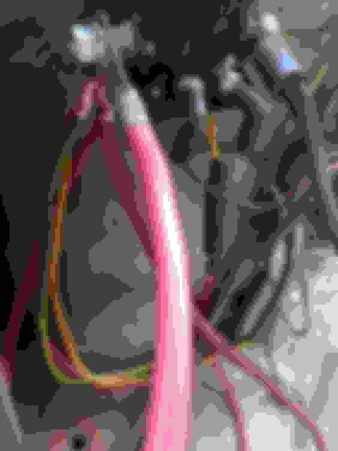
I have included some pictures to help me explain. The way this is wired, there are 5 wires that connect to the positive wire that goes from the alternator to the starter solenoid. The Hayes manual only shows 2, a yellow wire going to the voltage regulator and a blk/yel wire going to the ignition switch, and to a yellow wire going to the horn relay. The blk/yel wire should be a fusible link. The yellow wire going to the voltage regulator and the blk/yel wire are easily visible. The blk/yel wire, a yel/blk wire, and a red wire all to go the same plug and were all connected to the same wire.
The last wire in the mix is obviously not factory. It goes to the signal stat with a fuse in between.
There are 2 other wires connected to the alternator, an orange wire and a white wire. The Hayes manual shows them both going to the voltage regulator. The orange wire does but the white wire goes to a plug along with a red/grn wire coming from the voltage regulator. I cant see where any of the wires go after they go into the harness. Any ideas on what is going on?
It's difficult to iron out a bunch of wires going different places. It's easier to troubleshoot the charging problem, and then the wires may work themselves out.
I see you do not have a connection on the "I" terminal of the regulator. This tells me you have a ammeter gauge in the dash cluster. Is this true? Your truck is wired for it. There were some trucks that had only idiot lights in the dash, they would have been wired differently, this can be a problem if clusters are swapped or cabs are swapped.
First thing to check, see if that green/red wire going to the "S" terminal of the regulator has voltage on it when you turn the key to run. Go get a testlight, it's the best way to troubleshoot these things. You can also use a meter if that is what you have. Write back in with what you get on this wire.
It has an Alt gauge with a D at one end and a C at the other. The voltage on the red/grn wire is 12.7, same as the battery.
I wired everything back up except the 3 wires going to the same plug and no juice the starter. Should I just go ahead and twist these 3 together and run it to the positive side of the starter solenoid?
Problem still not solved. The alt is not charging the battery at all. Same voltage at the battery with truck running or not. Still not sure about this wiring. Should both of the small wires from the alt be going to the voltage regulator? Could the voltage regulator be bad?
When i took the pictures i was still in the middle of replacing wires. This is how it is currently wired.
Also i was noticing that the alt gauge is not working, it just sits in the middle.
The factory ammeter in those trucks hardly worked when they were hooked up. Yours will never work again, since you re-wired the output wire of the alternator. The ammeter is the least of your worries.
See that orange wire on the back of the alternator that says "FLD"? Take that wire off and tape it so it doesn't short out. Take another piece of scrap wire and hook it to that FLD terminal on the back of the alternator, and then lay it up by the battery area. Start the truck, put your meter on the battery, and then touch this FLD wire to the + of the battery. Does the voltage jump up on the battery?
Drove up to advance auto and had them check the alt that they sold me. Junk, no output at all. Ordered a motorcraft online but it will b a week before it gets here.
Franklin2, why do u say the gauge will never work again? Is it the way it is wired? I wired it back up the same as it was before.
Drove up to advance auto and had them check the alt that they sold me. Junk, no output at all. Ordered a motorcraft online but it will b a week before it gets here.
Franklin2, why do u say the gauge will never work again? Is it the way it is wired? I wired it back up the same as it was before.
That red wire going from the output lug of the alternator to the lug on the battery side of the solenoid is not factory. The factory had a calibrated shunt in this wire with two other small wires on either side going to the dash ammeter. You can see that wiring in the schematic I gave you in the link http://www.fordification.net/tech/im...ster_2of10.png
Open that diagram up again. Find the "starter motor relay". That is your solenoid. Follow that dotted line up till you get to the "38 BK-R fusible link". Follow that wire to the right, you come to a bracket and that gives you two choices, with gauges or without gauges. You have gauges, so you have to jump to the top line and go to splice 201 (S-201). That piece between splice 201 and 202 is the shunt. You will see on either side in the splices there are two other wires coming off the top, 655 and 654. If you follow these to the right they go off the page and say "charge start ammeter". Those are the wires to the ammeter.
If you go straight through that shunt and keep going right in the diagram, it drops down to another smaller bracket. From here it is still a 38 black/red, this is your alternator output wire. If you go back left to the small bracket, you can see the lower leg that is the "without gauges" option is the way you have it wired right now, straight to the solenoid battery lug. If you did not have gauges, you would have had a "gen" light in the dash.
Thank u for the step by step. Its wired just like the diagram with gauges except no shunt in between, they are wired together at the positive side of the solonoid. Will this cause a problem?
Put the new alt on and its charging perfectly, 14.6v at idle.
Now i have another problem. The last time that i drove it with the bad alt; it was night so had the headlights on of course. As i was on my way home the headlights were getting a little dim, since i was running off the battery only. I also notice the dashlights were getting dimmer and dimmer until by the time i got home they were completely out. Once i changed the alt, the headlights are still fine but the dash lights no longer work as well as all of the running lights. Brake lights, back up lights, and turn signals all work fine. Check the fuses, all are fine. In the wiring diagram it shows a brown wire that connects all of the running lights/parking lights. I followed this wire, dead with the switch on, all the way to the signal stat that is getting power from the battery through the fusable link. Does that mean the signal stat is bad or could it be in the switch? Does this have anything to do with the dash lights?
It shows both the running lights and the headlights are fed from the same power source, a black/orange wire. If the headlights work, then the headlight switch must be bad, or a wire is burnt off the switch plug.
This Hennessey Takes the Expedition Tremor's Off-Roading Capability to the Next Level
Slideshow: The VelociRaptor Expedition gains a lift, upgraded suspension, Brembo brakes, and trail-ready equipment while retaining the stock 440-horsepower EcoBoost V6.
Rezvani's Latest Post-Apocalyptic Monster Is a Ford F-150 Raptor Underneath
Slideshow: Called the Fortress, the 850-horsepower pickup combines Raptor underpinnings with military-inspired features, survival equipment, and a starting price of $285,000.