
Re-Pining Harness For MAF, C185 to C101
#1
 01-26-2018, 09:36 AM


Re-Pining Harness (94 5.8 & E4OD) For MAF
I have a fairly complete 94,5.0, trans "E", mass air underhood harness except for what goes across the firewall. (cut in the middle)
The basic idea is to use the 5.0 harness, C101 from fender liner out to top of engine, (injectors,ignition & sensors, etc) after cleaning it up.
Possibly deleting or leaving & coiling up knock sensor & PS pressure switch connectors/wires
Re-pin my existing 5.8 SD connector C185 @ PCM as needed to match the 94 MAF computer.
Add the MAF meter & filter box air temp sensor to a place most expedient. (Home run to 185 or go through 101?)
Problem is I'm dealing with Chilton's better than nothing wiring diagrams.
Could someone tell me if 101 to 185 is universal in the wiring & color codes across applications?
I found a '95 C101 illustration, M/F showing that they are, across the board 4.9, 5.0, 5.8 & 7.5
Last edited by Scndsin; 04-26-2018 at 09:36 AM. Reason: Update information
#2
01-26-2018, 10:48 AM

Fleet Mechanic
Not quite Ford EVTM quality, but try this link for wiring diagrams.
BBB Industries- Premium Alternators, Starters, Power Steering Products | TSB's & Wiring Diagrams
BBB Industries- Premium Alternators, Starters, Power Steering Products | TSB's & Wiring Diagrams
#3
01-26-2018, 11:37 AM
Hotshot
C101 has the same wiring across all of the gas engines according to my Ford EVTM manual.
C185 (PCM Connector) has differences based on whether the vehicle is using Speed Density or MAF as well as the various transmissions. This link from the old Ford Fuel Injection site is a great reference: Ford Fuel Injection
C185 (PCM Connector) has differences based on whether the vehicle is using Speed Density or MAF as well as the various transmissions. This link from the old Ford Fuel Injection site is a great reference: Ford Fuel Injection
#4
01-26-2018, 06:33 PM
Pretty much everything needed, but the trans wiring functions aren't listed.
Problem is, it does not tell me what wiring is 4R0W required vs E4OD.
Have a look at the "to transmission controls" portion on these 2 diagrams (top)


#6
01-31-2018, 06:32 PM
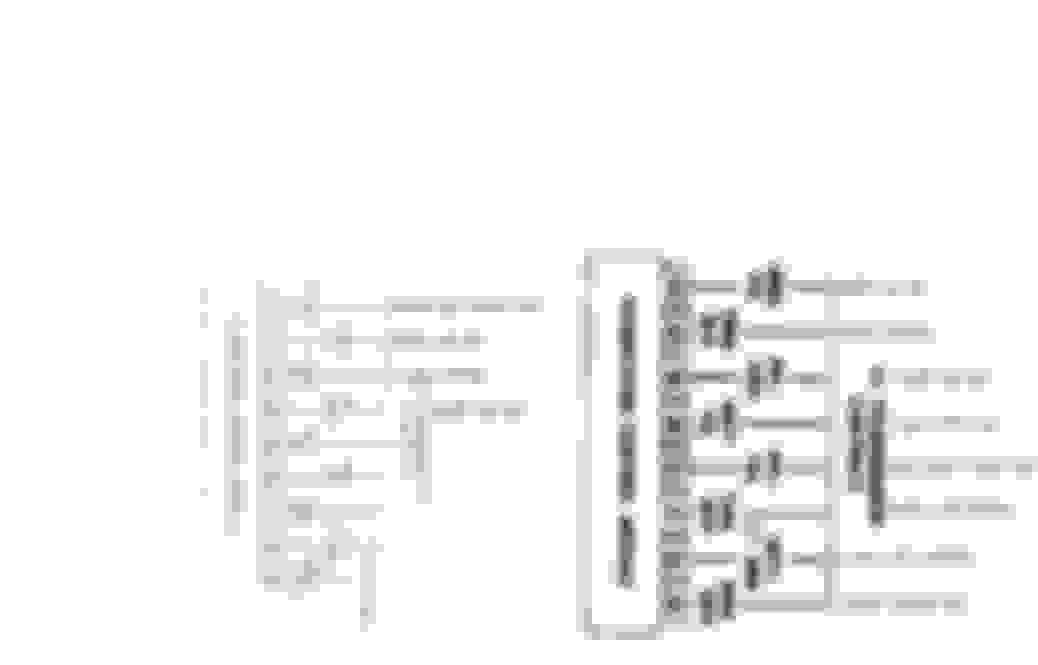
Managed to get the truck in the shop & pop the covers on C185 & C101.
Common wires from 5.0 to 5.8 are all there. The mass air injector wires aren't.
Was hoping they would be & all I'd have to add would be the MAF wires at 101.
Found out my black white runs back to a splice & back to pins 40 60 then to fender ground.
Managed find enough to see what needs to be re-pinned for the E4 since FFI's pin chart doesn't call out trans connections.
Not sure what to do with #30
5.0 on left, 5.8 on right.

#7
01-31-2018, 07:39 PM
Isn't that for a non computer controlled trans and not used with the E4OD.
Trending Topics

#9
02-01-2018, 08:45 AM
Hotshot
#10
02-01-2018, 09:58 AM
Could some body (if able) help a sister/brother out & post a fresh, larger, higher rez image of this?
Actual 94 would be great, but I'll take 95
It's the best one I can find & I can't see **** worth a damn to work consistently.
Printing out doesn't help, washes out terribly.
C101 would help too if possible.
Thanks.

Actual 94 would be great, but I'll take 95
It's the best one I can find & I can't see **** worth a damn to work consistently.
Printing out doesn't help, washes out terribly.
C101 would help too if possible.
Thanks.
#11
02-01-2018, 02:23 PM
Hotshot
#13
02-01-2018, 04:32 PM
Fleet Mechanic