


Ballast wire

Thread Starter
|
Senior User
Joined: Dec 2016
Posts: 210
Likes: 0
Dan
Thread Starter
|
Senior User
Joined: Dec 2016
Posts: 210
Likes: 0
also just put the Ford points and condenser in today and don't want to ruin them if I have a resistor problem. Thanks
Hotshot


Joined: Mar 2013
Posts: 14,255
Likes: 199
From: Phoenix, Az.
Yes I checked it while running and it is 12v. Maybe it's been 12v this whole time and I just checked last time with the points one way or another like you said, when engine was off. I don't think I ever checked it while running before. Maybe that's been my problem all along with it. I haven't had the truck Very long. So, it should be about 6v while running, correct? Thanks
Dan
Dan
So I quote myself.
You can either replace the existing coil supply wire with the C0LF12250A pink resistor wire or leave that 12V wire there and install a hotter coil meant for a 12V supply. Like:
ACCEL SuperStock Ignition Coils 8140
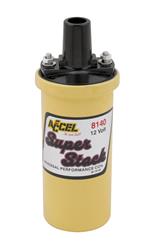
$27.51 at Summit. Prolly available at your local Big Box parts stores like Ore*lly's or A*tozone.
__________________
Hotshot
Joined: Mar 2013
Posts: 14,255
Likes: 199
From: Phoenix, Az.
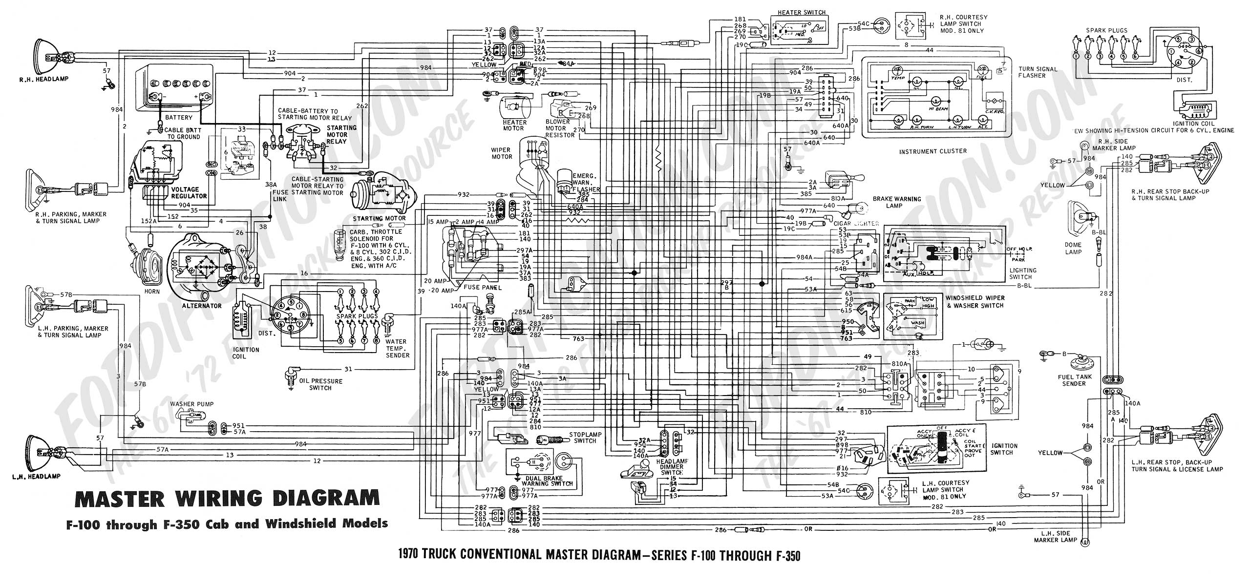
Notice circuit #16 coming from the ignition switch. And circuit #262 coming from the starter solenoid. The connector they join at is just about center of the schematic below. Then #16 continues on to the coil. Only the 1st 1/2 of #16 is resistor wire.
Thread Starter
|
Senior User
Joined: Dec 2016
Posts: 210
Likes: 0
Ok, Jeffafa I understand. I just thought this discussion should stay on this thread since it started here actually. I just went out and disconnected the wire from the "I" terminal and the truck still started. I can get a 12v coil fine, but what happened in the last two weeks because I DID have just 6v at the coil, now it's 12. I have a pink resistor wire that goes from the ignition switch over to a plug where it meets up with the other wire like you said and then it goes to the coil via a red w/green stripe wire. But the pink resistor wire is part of the harness. It doesn't have connectors like the replacement wire shows? How do I replace it? Thanks
Dan
Dan
Thread Starter
|
Senior User
Joined: Dec 2016
Posts: 210
Likes: 0
FTE Stories
Ford Trucks for Ford Truck Enthusiasts

3 Best / 3 Worst Parts of Modern Ford Ownership
Brett Foote
10 Amazing Upgrades That Solve Common Ford Truck Owner Headaches
Pouria Savadkouei
Every 2026 Ford Engine Explained
Brett Foote
10 Ugly Ford Trucks That We Still Kinda Love
Joe Kucinski
10 Things Every Truck Owner NEEDS (2026 Edition)
Michael S. Palmer
Rezvani's Latest Post-Apocalyptic Monster Is a Ford F-150 Raptor Underneath
Verdad Gallardo
Top 10 Most Expensive Ford Trucks Ever Sold on Bring a Trailer
Joe Kucinski
2027 Ford Super Duty Buyer's Guide (Every Model, Engine, & Package)
Brett Foote
Top 10 Ford Truck Tragedies
Joe KucinskiHotshot
Joined: Mar 2013
Posts: 14,255
Likes: 199
From: Phoenix, Az.
Is there something else hooked up with 16,262,and 16? You got a pic of the connection? If the "whole" pink wire is there and you still got 12V at the coil while it's running, with the "I" terminal disconnected, the 12V has to be coming from an outside source.
Thread Starter
|
Senior User
Joined: Dec 2016
Posts: 210
Likes: 0
Here's some pictues of the NAPA points after 9 days. Also pictures of the plug to the ignition switch and then pictures of the plug labeled "D" on the ignition wiring diagram.
Also, just to make sure I'm not a complete idiot, the 12v I measure at the battery side of the coil, coming from plug "D" is just measured to ground, I have 12v to ground there. If I measure between the two posts on the coil while it is running, I get 5v. I can unplug terminal "I" on the relay and the truck starts anyway. I don't know why that is. I didn't see where anything else is wired to the coil. I also don't see any pink wire that can be replaced, just the pink wiring in the pics that are part of the harness. Thanks, sorry to be a pain.
Dan
Post Fiend
Joined: Apr 2002
Posts: 19,311
Likes: 97
From: Waterloo, Iowa
Just measure the entire primary resistance. With points you want to see around 3 ohms total. The pink wire is connected to the ignition switch, it's only pink under the dash, it is spliced somewhere in there, and then goes on to the solenoid.
Remember the ignition gets a full 12 volts only during START (ballast bypassed) to help in cold weather, and then only runs through the ballast (pink wire) during RUN to drop the voltage down.
Stock coils had a primary resistance of around 1.4 ohms + the ballast of 1.3 to 1.4 ohms. So the entire primary resistance is around 3 ohms, plus whatever 50 years of corrosion at all the connections does.
Your points look good btw. Use a dwell meter for accuracy, the feeler gauge setting just gets "close enough". Re-adjust timing after points are set. Don't forget a little bit of cam grease on the rubbing block. They will wear in a little bit the first 50 miles maybe too. Re-set after they run in. The cheap points, the rubbing block just wears away no matter what lol.
Thread Starter
|
Senior User
Joined: Dec 2016
Posts: 210
Likes: 0
Just measure the entire primary resistance. With points you want to see around 3 ohms total. The pink wire is connected to the ignition switch, it's only pink under the dash, it is spliced somewhere in there, and then goes on to the solenoid.
Remember the ignition gets a full 12 volts only during START (ballast bypassed) to help in cold weather, and then only runs through the ballast (pink wire) during RUN to drop the voltage down.
Stock coils had a primary resistance of around 1.4 ohms + the ballast of 1.3 to 1.4 ohms. So the entire primary resistance is around 3 ohms, plus whatever 50 years of corrosion at all the connections does.
Your points look good btw. Use a dwell meter for accuracy, the feeler gauge setting just gets "close enough". Re-adjust timing after points are set. Don't forget a little bit of cam grease on the rubbing block. They will wear in a little bit the first 50 miles maybe too. Re-set after they run in. The cheap points, the rubbing block just wears away no matter what lol.
Remember the ignition gets a full 12 volts only during START (ballast bypassed) to help in cold weather, and then only runs through the ballast (pink wire) during RUN to drop the voltage down.
Stock coils had a primary resistance of around 1.4 ohms + the ballast of 1.3 to 1.4 ohms. So the entire primary resistance is around 3 ohms, plus whatever 50 years of corrosion at all the connections does.
Your points look good btw. Use a dwell meter for accuracy, the feeler gauge setting just gets "close enough". Re-adjust timing after points are set. Don't forget a little bit of cam grease on the rubbing block. They will wear in a little bit the first 50 miles maybe too. Re-set after they run in. The cheap points, the rubbing block just wears away no matter what lol.

Post Fiend
Joined: Apr 2002
Posts: 19,311
Likes: 97
From: Waterloo, Iowa
Well I guess looking at thumbnail pics doesn't help. Did you clean them before install? They sometimes need it, they get a layer of skunge on them, especially engines that haven't ran for a long time. Wonder when those were manufactured? That's usually what causes pitting, is dirt or grease.
Measure the positive side of the coil at idle, it's 12 volts while running, or 6-7 volts?
Anything could have been done to the truck after 50 years. If the ballast resistor wire has been removed or bypassed, you can either replace/reinstall it or, install a coil with more resistance to make up for it. Bosch makes a blue coil of around 4 ohms that would work with no ballast wire required.