When you click on links to various merchants on this site and make a purchase, this can result in this site earning a commission. Affiliate programs and affiliations include, but are not limited to, the eBay Partner Network.
After a bit of thought on where to put this information I decided this is the best location. Another member, crewcabber, and I have been bouncing this around on Facebook.
The first issue is control panel, the 1992-1996/7 trucks have an HVAC panel the same size as a lot of the EATC systems Ford used, earlier than 1992, say 1980-86 or even 1987-91, I can't say for sure, and the 1980-86 models had the fuel tank selector switch in the HVAC controls.
Second issue is the air flow in these trucks vs the newer trucks and most cars. The trucks use a face vent or floor defrost mode door and a no, partial or full defrost door, these are vacuum actuated. Later trucks and most cars use a upper or lower distribution mode door with a full upper, mix, and full lower position with a face or defrost door in the upper distribution. As a result most of the EATC systems are designed for this, giving you the bi-level features my 1994 Taurus has, floor/defrost and floor/dash in addition to full auto, max A/C, normal A/C, vent and defrost. Here is a picture of a 1996 truck heater case with the items mentioned identified.
The other problem, starting in 1995 Ford actually phased in the OBD-II systems on cars, with the OBD-II system, there is a twisted pair or communication wires that are used by various components to "talk" to each other in addition to allowing a fairly standard diagnostic tool to be used. When this rolled out, Ford redesigned the EATC controllers to use this network. One of the needed items on an EATC system is "cold engine lockout" so you are not blasted with ice cold air at full blower speed as soon as you start the vehicle, A/C demand will over ride this. All Ford EATC systems for vehicles with OBD-II capability do not have a separate CELO system, the EEC tells them "OK, heat now". My truck is converted to a an EEC-V which is OBD-II.
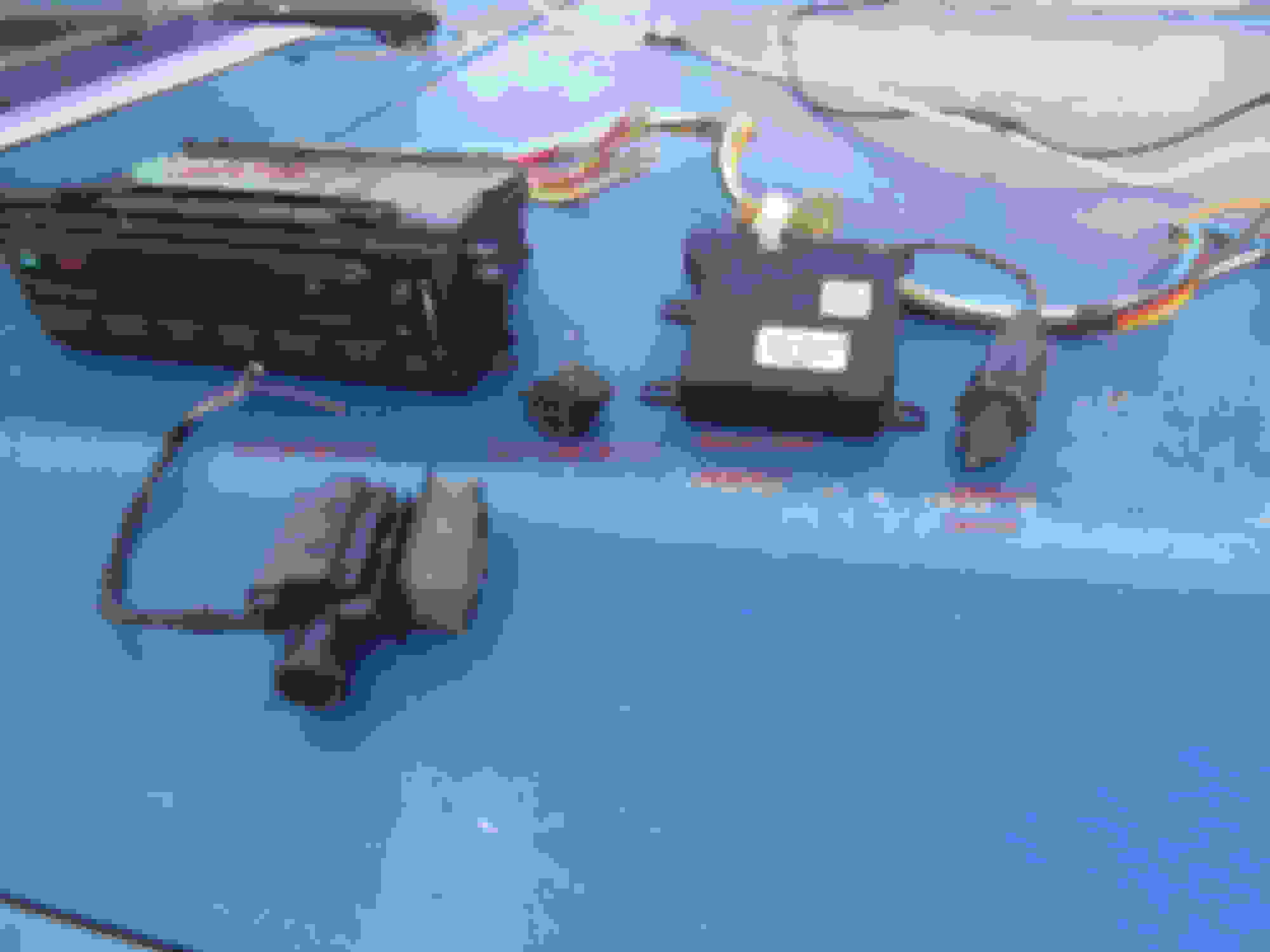
In prowling through a local junkyard, I found a 1999 Crown Victoria with this control panel.
You will notice the manual mode buttons match the truck **** or lever settings, with max A/C, normal A/C, vent, floor, floor defrost and defrost. I proceeded to remove it and the sensors and blend actuator.
Not knowing the exact location of the blower control module I couldn't locate it so have to go back and get it and the sunload sensor pigtail.
After getting it home, the next step was to verify whether it would work or not. I used wire nuts for now to connect the actuator, in-car and ambient sensors. I used an old 12V 3 amp power supply as that would give me enough for the display and solenoids so I could test it.
Set for max cool, actuator arm is fully (90�) CCW as viewed from bottom.
Set for max heat, actuator arm is fully (0�) CW as viewed from bottom.
Outside temp display (room temp).
Success! Now comes the fun, installing it. The easiest way is going to be to remove the dash to run the wires neatly. I will probably do that and run all the wiring, add the tube for the in-car sensor and the needed holes for sunload and in-car sensors. Fortunately, even using the 1996 harnesses, since the truck and donor truck are both > 8500 GVWR, there are no air bag wires so I have a number of empty pins in the main bulkhead connector, C202 for the ambient sensor wires and if needed the 3 small wires for the blower motor speed controller which goes underhood on the 1999 Crown Victoria.
I went back to the junkyard Thursday and retrieved the pigtail for the sunload sensor and got as much of the blower wiring underhood as I could. The speed controller was gone, and of the other two Panther platform cars, one was also missing, the other was a manual system. I looked at the price on-line and it ranged from around $35 to $85 with that being Motorcraft. I decided to just buy a new one and went by Autozone while I was out and picked up one of their Duralast lifetime units.
Outside portion.
[I]Connector, two large pins are blower motor negative and ground.[/I
Items that need to be added consist of:
1 - Ambient temperature sensor, mounts in front of condensor
2 - In-car temperature sensor, on Crown Vic, has a small grille in dash
3 - Sunload sensor, needs a hole in the dash facing up
4 - Blower motor speed controller, on Crown Vic, is on inboard side of underhood case
5 - Blend door actuator, on Crown Vic mounts on top of heater casing
7 - Aspirator hose air source, needs to come from system underhood case, or at least upstream of blend door
8 - Wiring, I have enough pieces for the various components, but they need to be connected to the components.
9 - Control head, should bolt right in
10 - Power sources, 3, one always on and two on in run.
11 - Vacuum harness, hopefully the in-line connection is the same on both vehicles so that will be simple
Wiring discussion:
Item 1 needs two wires, a light blue with orange and a pink with black run from the front of the truck, through the firewall to the control head. Item 4 needs a location, then wiring run through the firewall to the control head and a suitable ground. Item 2 needs a location, then two wires run from it's location to the control head, a white with orange and a pink with black. Item 3 needs a location and two wires run from there to the control head, a brown and a pink with black. Item 4 needs a location and a total of 5 wires, 3 of which go to the control head, one to the blower motor and one to a good ground. Item 9 needs it's connector plugs installed, and in addition to the previously mentioned wiring, needs, for my truck and any other OBD-II truck, the two wire twisted pair for the multiplex communication network tied into the existing pair. Item 5 needs it's 5 wires run from where it will be mounted to the control head location. I am somewhat **** about my wiring, no crimps, everything soldered and heat shrink tubing used over it and I prefer to make it as neat as possible by running it along and taping it to the factory harnesses. I also prefer to use the factory bulkhead connectors. This means the dash has to come out in order to run the majority of the wires. This will also help in the installation of the sunload sensor, in-car sensor and blend door actuator.
What I will probably do is once locations have been determined, including the blend door actuator, I will remove the dash and do all the wiring additions, but not necessarily install the system at that time.
Ran into a problem with the mechanical fit up. The space between the mounting surface and the A/C duct is too shallow for the module. What I plan on doing is, at a minimum, remove the solenoid pack (4 of them) to a remote location like the newer SD and Excursions do. Worst case I will have to mount the internal electronics board remotely.
I did verify that the vacuum harness connectors are the same so that that part becomes easy.
Vacuum harness connector and shallow recess for module.
Update, space in the dash opening for the HVAC controls is 3" deep, the circuit board, without electrical or vacuum connections is right at 4" front to back. It will have to be mounted away from the front panel. The front panel is connected to the main board with two 8 conductor heavy ribbon cables and a 5 lead set from the blower manual speed rheostat and light bulb that goes on the top about 1/3 of the way back. Loads of fun, and we do not have a Radio Shack or similar here to get a suitable box from.
Other item, I verified the rotation direction on the blend door actuator, it moves 90� degrees at the lever and looks like if I can mount it to the main part of the case it will not interfere with a heater care replacement.
Inside case with temperature control cables (late style) attached.
These are a bit hard to see, but the pink colored piece is the blend door lever, in full heat it is parallel to the firewall, in full cold it is perpendicular in a 90� rotation clockwise viewed from above. Actuator has the same position and rotation.
Not that I have found so far that will match the air distribution layout of our trucks. Once I get the basic layout sorted, I will see how it can be resolved.
Ok, I finally got a chance to play with the EATC setup again. I installed the ambient sensor in the front and ran the wires back to the bulkhead connector.
Now, when I have time to pull the dash out I will run the inside wiring and install the control head which due to the shallow depth of the area is going to have to be in two pieces.
I like where this is going and the attention to detail you're putting in with the wiring to make it presentable, intelligently routed and serviceable if the need arises. You took it a step beyond by adding terminals to integrate it into the correct routing/bulkhead connectors too. Nice touch!
Remote mounting the four solenoids won't be too hard once you identify the power/signal wires for each one. If you have a sketchy one, you might even consider different solenoids entirely as I did with my RX7s twin turbo control system. As long as you can get the vacuum lines connected, who cares where they came from The included picture may give you some ideas, look in the bottom left corner to see my solenoid rack for the twin turbos..
As for the control box, here's a simple idea: cut a section out of the middle, then glue/weld/etc the front and rear pieces back together. Look for a polymer ID on the box so you can properly mate the halves back together
I had looked into that, simply sectioning the case and if necessary moving the four solenoids elsewhere. Not a real good option. The main circuit board occupies entire depth of the case on the bottom. My plan now is to separate the front panel and main internals and use a male/female computer ATX power supply plug pair (24 pins) this will allow for the 21 wires between the front panel and main board leaving the main board and vacuum valves to be mounted remotely.
I had looked into that, simply sectioning the case and if necessary moving the four solenoids elsewhere. Not a real good option. The main circuit board occupies entire depth of the case on the bottom. My plan now is to separate the front panel and main internals and use a male/female computer ATX power supply plug pair (24 pins) this will allow for the 21 wires between the front panel and main board leaving the main board and vacuum valves to be mounted remotely.
That is a good idea, but I'm not too keen on using an ATX connector where more suitable ones are easily available. If the wiring for these devices is 18awg or bigger (18 is the smallest I mess with, I'm not too good with soldering), you can use any connector you want.
My goto connectors are Delphi Metripack 150 sealed connectors, but they are limited to 10 pins max. But since you're handy with a soldering iron, check out Tyco Electronics (now TE Connectivity) Superseal 1.0. Haltech ECUs use them, as do several Chrysler minivans. The PCB ones can be soldered onto jumper wires with some finesse, while the harness side ones are crimped. They come in 26, 34 and 26+34 pin versions.
The original connections are two eight conductor ribbon cables, probably 18ga. then there are 5 more for the manual blower speed rheostat and light. As far as suitability, these are more then adequate since they will be inside the cab. For all my exterior wiring, I have a large collection of Ford connector pairs from 4 pin to 42 pin with the seals and I buy the male/female pins from RockAuto for the .125 wedgelock and Clips and Fasteners for the AuVeCo .062 male/female Wedgelock. Both of these are crimped on, but I solder them for a more secure electrical connection.
FWIW, I rewired the entire truck from the original 1986 system to a 1996 system and changed the dash and interior to a 1996 system. Go through some of my other threads, truck now has automatic headlights and a few other not originally offered options.


 The included picture may give you some ideas, look in the bottom left corner to see my solenoid rack for the twin turbos..