When you click on links to various merchants on this site and make a purchase, this can result in this site earning a commission. Affiliate programs and affiliations include, but are not limited to, the eBay Partner Network.
I have set aside the project for a few weeks. I have a buddy who has done a couple and he will return to states soon, so will get it done then. In the interim, I�ll continue work on the truck and just run a carb.
Also, all of the 8.8�a I have are 84,85,85... so no VSS. I will just grab one somewhere.
Also, gonna consider a slightly older ECM for a manual.
I know this thread has a couple years on it, but it is an excellent example and I have a specific question on the work done.
What happened to the bank of round connectors at the takeout just upstream (relative to ECU connector) of the 4 round engine harness connectors? These would presumably be for rear of truck and/or transmission control. Connectors in question are green, white with black cap, white, brown, gray, and black. They are shown in the as-removed harness but quickly disappear in the subsequent pictures. Were those group of wires that interfaced with the ECU unpinned from the connector?
Context: I am planning on dropping a '91 E350 EFI 460 into my 1980 Bronco. The 460 was paired with an E4OD. I have the engine and engine bay van harness (and EVTM) and another semi-hacked harness I salvaged out of '91 F-250 with a 460 and E4OD. I have the ECU from the van. I am keeping my current C6, so I don't need any electronic transmission control. I would like to remove the transmission control circuits for harness cleanup as shown here, but wanted to confirm the method by which those connectors disappeared. Would there by any concern with the ability of the ECU to operate the engine without transmission pins in the ECU? I don't have a CEL so not terribly concerned about lights or codes.
Thanks and great write up.
Originally Posted by NotEnoughTrucks2014
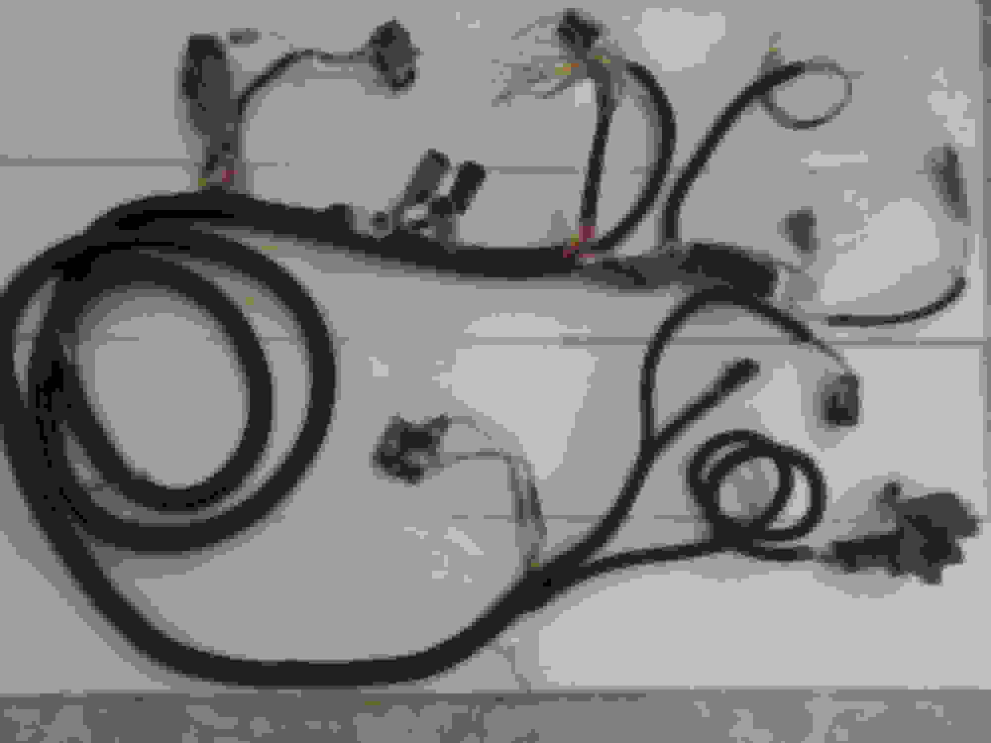
Thought I would document how I dug the EFI circuits out of a 90 F150 harness.
Could go many places on this site. Mods, if it fits better in Electrical, or the bricknose/OBS forum, please feel free to move it. Thanks.
EECIV Standalone Wiring Harness
Harness as removed from 90 F150.
It is important to maintain order and avoid distractions when you have the bundle open. It's easy for the harness to morph into a frustrating ball of snakes. Give yourself plenty of room and lay the harness out in a line. I used a 2X4 and some dollar store tool hooks to make a jig that I could tie the harness to. Really helps maintain order. Also got some velcro cable ties to help with separation and bundling.
What happened to the bank of round connectors at the takeout just upstream (relative to ECU connector) of the 4 round engine harness connectors? These would presumably be for rear of truck and/or transmission control. Connectors in question are green, white with black cap, white, brown, gray, and black. They are shown in the as-removed harness but quickly disappear in the subsequent pictures. Were those group of wires that interfaced with the ECU unpinned from the connector?
Yes, they were for the body functions for the rear of the truck and were pinned mainly to the circular firewall connector. The fuel pump circuit also ran this path, but it runs through the tank switch and inertia switch inside the cab.
I'm attaching a photo out of my factory wiring diagram book. It's pretty large scale, so I can't scan it in it's entirety, but hopefully you can enlarge sufficiently to see the detail. The four engine connectors can be seen in the lower portion of column 29 and I think two of the body connectors show in the upper part of that column. This diagram was for wiring w/o E4OD and I think the transmission connector is similar, but does wire to the ECU. The example I dissected did not have the E4OD.
Thanks Ray. I'm losing resolution fast blowing them up on the computer screen, but I'll have access to a plotter next week and may print C or D size prints and see how they do. That info is much better than anything I have in my EVTM.
You helping confirm most of the connectors are just pinned to the firewall connector, which I had planned to unpin anyway based on your thread, gives me some confidence to start opening up the truck harness and seeing what I need to repair/add to make a standalone EFI harness.