When you click on links to various merchants on this site and make a purchase, this can result in this site earning a commission. Affiliate programs and affiliations include, but are not limited to, the eBay Partner Network.
I am not sure how your winch works, I bet you are not sure either. What I am not sure of is the field terminals and their wiring. If it's like I think it is, f1 and f2 are the field coil. If that's true, then your diagram won't work, f1 or f2 need to be grounded for it to run.
Looking at the diagram you chose, it's almost like f1 is one field coil and f2 is another field coil, both coils grounded internally. I suppose this could be the case, but you need to check it out. What I would do;
Get a ohmmeter and set it on rx1. With no wires hooked to the winch, touch one meter lead to f1 and the other meter lead to the metal case of the winch. See if you get a reading. Then move to f2, leave the other lead on the case. See if you get a reading. Then put one meter lead on f1, the other on f2, and see if you get a reading(nothing on the case ground). Just to double check, put one meter lead on "A" and the other meter lead on the case ground.
From these tests we can figure out what you have going on there.
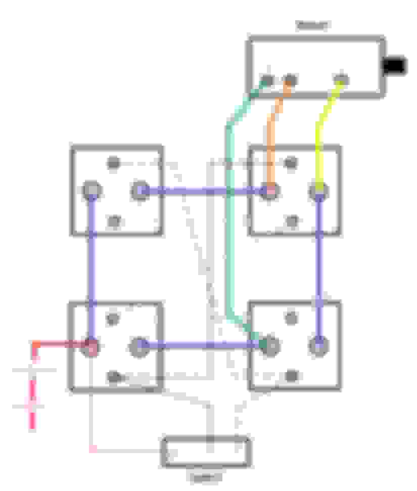
Ok, I see what they are doing now. This is called a "series" DC motor. The current goes through the field, then the armature, and then to ground which goes back to the battery. To change direction they swap the terminals of the field coil, which changes the polarity of the field coil in relation to the armature and makes the motor reverse.
When you put power on the brown dotted line, it makes a connection in the lower left contactor which puts power on the green line from the red line. Power goes into F1 and comes out on F2. It runs down the orange wire and takes a right through the upper right contactor(since it's hooked to the brown wire) and goes up through the yellow wire into the A terminal, through the armature and then to the case ground and back to the battery.
When you put power on the grey dotted line, power goes from the red to the blue and then through the upper left contactor to the blue and then the orange wire and into F2. It comes out on F1, goes down to the lower right contactor and then to the armature just like before.
If you notice, the path through the field has been swapped. The brown wire makes the current go through f1 first and then comes out on f2. With the grey wire it goes through f2 first and comes out on f1
The smaller posts on the solenoids are labeled "I" and "s". I'm guessing all of the ground wires to the "I" posts and all the "s" posts to the switch?
No. Sounds like you have regular starter solenoid/relays. The "I" is for the ignition coil, leave it alone no connection. Your common grounds will be the mounting foot of each contactor.
These automotive starting contactors that you have are only rated for momentary use. I would go ahead and try them, but if you find they don't last they make contactor/relays rated for continous use.
Wired everything up but does not work.
The solenoids would not work unless I grounded the "I" posts.
Winch motor doesn't move, solenoid makes noise, motor,solenoids and wires were getting hot.
The voltage passes thru all the correct wires/posts just like on the diagram but there is voltage drop. 7.4 volts at some posts and 1-2 volts at the "A" post on the motor. The motor and wires were getting to hot to wire down all the voltage.
Should I be running a ground wire from one of the bolts that holds the winch to the battery?
Would the winch work at all if I was using the incorrect solenoids?
The wiring you are using, what size is it? I would think it needs to be at least #6 like your automotive battery cables.
Did you ever test the winch? If you haven't, take one of your #6 wires and hook one end to the F2 terminal and the other end to the A terminal. Get a car battery and using jumper cables, clip the negative jumper cable to the neg of the battery and clip it to a good ground on the winch. Then put the + jumper cable on the + of the battery and then touch it to the F1 terminal and see if it runs.
If you want to see if it runs the other way, move the jumper from f2 to A over to F1 and A, and put the + lead of the jumper on F2
I'm using #2 with new terminal that are crimped and soldered. I've tested the motor before and it worked in both directions. It was a few months back when I tested, I'm going to test again to be sure.
 06-14-2015, 03:30 PM