When you click on links to various merchants on this site and make a purchase, this can result in this site earning a commission. Affiliate programs and affiliations include, but are not limited to, the eBay Partner Network.
I like that offset, but I think you'll have to cut the flare off and move it closer to the bend. Looks like if needed, you could also shorten up the straight between the bends.
Yes, I do think that it will need to be shortened so that it moves the pipe away from the transmission sooner.
Something like the pipe on the right in the image above.
Flowney, great work and great methodology as always. Keep up the progress
Originally Posted by 1320stang
I like that offset, but I think you'll have to cut the flare off and move it closer to the bend. Looks like if needed, you could also shorten up the straight between the bends.
That's a great suggestion.
Originally Posted by flowney
Yes, I do think that it will need to be shortened so that it moves the pipe away from the transmission sooner.
Something like the pipe on the right in the image above.
Looks good to me! I would opt to have the offset utilized in both the X and Y directions as it's travelling down your frame channel. The exhaust will sit a bit lower overall, but it will also create a much larger gap between itself and the transmission (protecting your big $$$ investment).
Those pipes shipped today. I also ordered a bunch of 4" connectors to help with the mock-up process now that the straight back option has been tabled. Those connectors will enable me to more easily play around with various configurations.
Designing, Fabricating and Installing an Exhaust System, Part II
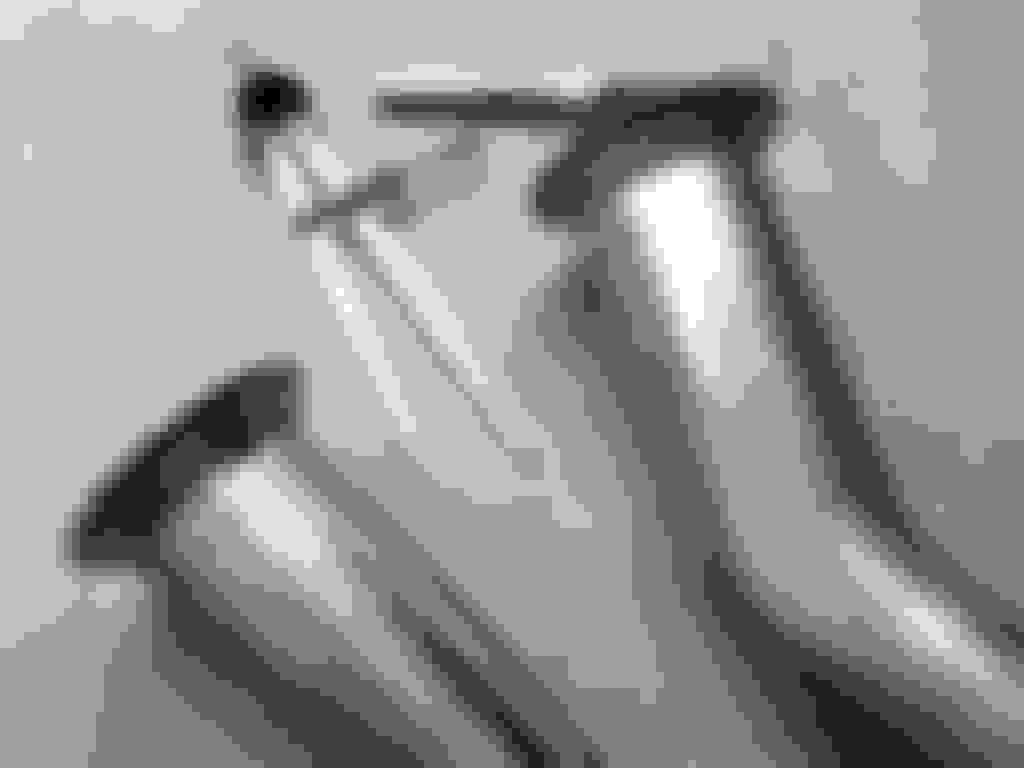
The offset header extensions arrived today so I got a chance to evaluate my options, especially with regard to the transmission crossmember.
To better visualize the transmission crossmember situation, I repositioned the jack stand holding the transmission up so that I could put the crossmember in its proper place.The header extension can be turned so that it goes over the transmission crossmember as illustrated here.
The header extension can also be turned so that it can almost go under the transmission crossmember as illustrated here. If I go this route, it will be necessary to fabricate a relief notch in the transmission crossmember.
Regardless of which route is taken, shortening the first straight in the header extension will further improve the clearance between exhaust and transmission avoiding heat transfer in the process. This is the passenger side.
The same will be true of the driver side.
Here, the trans crossmember is in its correct position with the exhaust pipe raising it slightly.
Going under the crossmember brings the exhaust system below the frame rails but nowhere near as low as the suspension components. A similar bend could be used to raise the system back to the level of the headers.
So the decision is still whether to go over, around or through the existing crossmember or fabricate a new crossmember. At least this mock-up and these pictures help one visualize the problem.
The biggest worry that I would have about going under the cross member is making that section of exhaust removable in case the cross member ever needs to be removed at a later date.
The biggest worry that I would have about going under the cross member is making that section of exhaust removable in case the cross member ever needs to be removed at a later date.
That's kinda why I liked it. Only thing is, its sorta close to brake and fuel lines.
Maybe use spacers under the crossmember, where it rests on the lower C-channel of the rails, and then notch the center of the crossmember, where the transmission mount mounts up?
I'm thinking that anything much more than 1/3rd or 1/4th of the pipe's diameter, which protrudes, or is lower than the frame rails, is less than elegant - at least that's the impression I get, looking at your pics.
I would go over the crossmember. First, like you said, shorten from collector to first bend. Second, shorten just about an inch between the bends so that you are away from brake and fuel lines (also, think about heat shields along that side, better safe than sorry) and out of the frame on the other side. The rest of the exhaust should go in beautifully.
Designing, Fabricating and Installing an Exhaust System, Part III
The offset header extensions will need to be modified so that the transmission won�t be exposed to more radiated heat than necessary. At the same time it will be important to keep that heat away from the fuel and brake lines that are routed inside and along the driver side frame rail. The third challenge will be to navigate around the transmission crossmember. Three birds with one stone.
Here, I�ve used a divider to scratch a line 1.25� from the flange of the header extensions and then traced over that with a Sharpie to create a more visible line to guide cutting.
A hand held band saw was used to make this first cut as well as �
� a second cut 3� further down. The shortened header pipe shown here is ready for a few spot welds.
This modification brings the bend 3� closer to the collector so that the exhaust pipe moves away from the transmission much sooner than otherwise.
The result f this shortening is quite dramatic on the passenger side as well as �
� on the driver side.
A second pair of offset header extensions was purchased. I removed the collector flange and then used a 4� coupler to mock up this second pipe up in the truck with the transmission crossmember in place. Once the desired combination of angles was achieved, a guide line was drawn on both pipes. Removing the coupler, I extend the lines to the end of each pipe. Shown here is the jig I used to line the pipes up for spot welding.
This is the driver side all tacked and ready for test fitting.
The passenger side clears the transmission crossmember nicely as does �
� the driver side.
I have also purchased a universal H-pipe kit to precede the mufflers and whatever comes after that. From what I�ve read H-pipes are better than X-pipes at lower RPMs in that they deliver enhanced torque.
Designing, Fabricating and Installing an Exhaust System, Part IV
As I looked around under the truck, it became apparent that I needed to remove the rest of the old system and deal with some of the hacked-up stuff associated with it.
I had to remove the trailer hitch in order to get the remaining pipes out. The PO had already severed all the wires going to the receiver so that will be something to sort out in the future. The hitch looks to be well designed and stoutly built. As well it appears to leave plenty of room for a deeper fuel tank with greater capacity. I�m not sure yet what to do with those chrome resonators.
So, those parts have been stashed away pending further decision making.
Since I won�t be using the midships tank, I suppose that this plumbing and wiring ought to go.
This crossmember was cut in half and crudely braced in order to accommodate the dual mufflers on the passenger side while continuing to support the midships fuel tank on the driver side. This needs to go but that won�t be easy because it is riveted to the frame.
The first thing I do with frame rivets is use a flat file to create a small flat spot at its highest point. I then take a center punch to that spot creating a starting point for a 1/8� pilot hole. That pilot hole needs to be as deep as the rivet head is tall.
I then follow that with a 1/2� drill �
� which should remove the rivet heads if the pilot hole wasn�t too far off.
The remainders of the rivets are now ready for a little pneumatic persuasion.
Rivets punched out, these hacked-up brackets are now out of the way. The other half of this bracket is lost to the sands of time but that�s OK since I�m not going to be replacing the midships fuel tank.
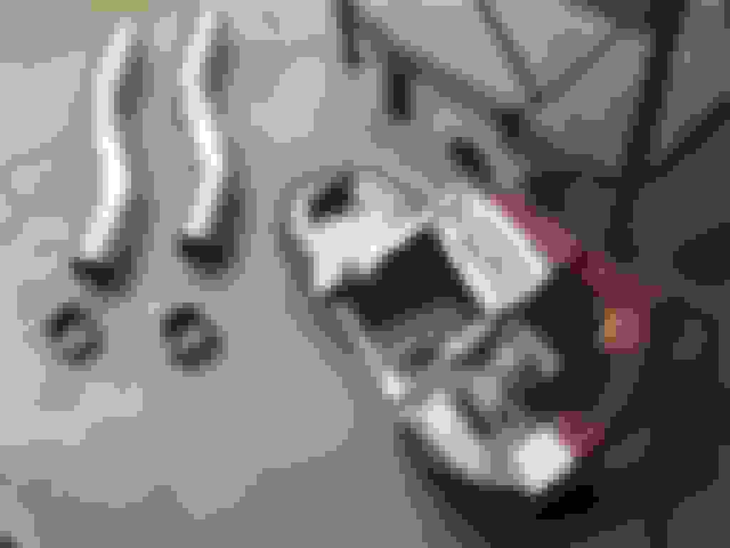
So, on to finishing this plumbing job. The H-pipe kit comes with two cross pieces. Here is the straight one. Also shown are the two 45� mandrel bent pieces I have on hand.
Here is the bent cross piece which may be needed to provide extra clearance to the drive shaft.
Finally, I also have two 90� mandrel bent tubes to work with. Here, I show how the 90� and 45� bends can be used together. Not shown are two lengths of straight tubing and a number of 4� connectors. I haven�t yet sourced any hangers.
With all of these pieces, I should be able to develop a system that looks and sounds OK.
I used this slip joint to establish and mark the angle at which the header extension pipe would have to be cut.
Using those cut and alignment marks, I was able to place a few spot welds for this trial fitting. So far so good.
Each step in this ad hoc process requires unbolting and removing the header extension from the header collector. Measure, cut, trial fit, adjust as necessary, repeat. Here, I have cut about 18� off the end of the 4� straight in order to mock up the crossover pipe and Flowmaster 40 Series muffler. I will need to move the muffler a little toward the engine in order to effectively use the crossmember from which I hope to mount the muffler hanger.
With the transmission crossmember removed for this stage of the exhaust system build, one can more easily see how the space between the transmission and the header extension pipe has been substantially increased. Here we see the passenger side and �
� here we see the driver side. The potential for heat to be transferred to the transmission is much less now. Although I was careful not to get too close to fuel and brake lines on the driver side, I still may fabricate an aluminum barrier just to be extra sure.
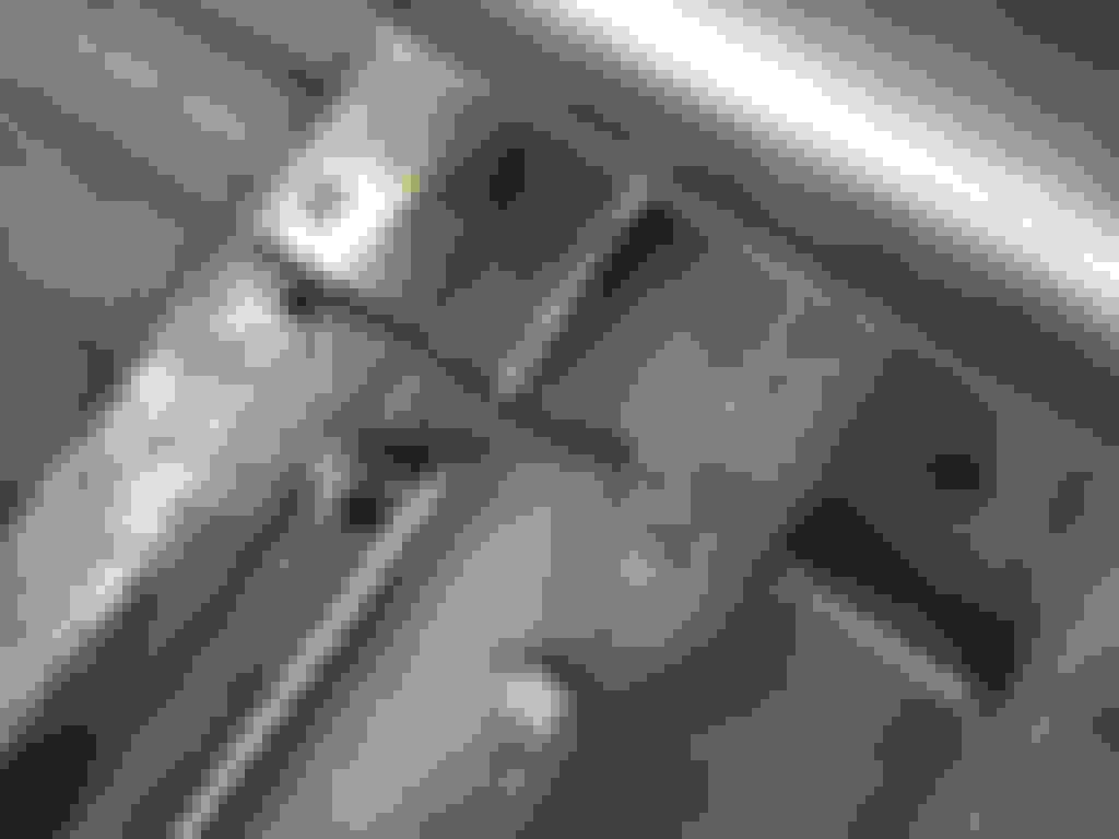
Continuing with the trial fitting process, I placed the �T� fittings for the crossover pipe and cut the bent version to fit. The kit also supplies a straight crossover pipe but because that option seemed more likely to come in contact with the drive shaft at some point, I opted to use the one that provided the most clearance.
Note that the cuts were made so that the bend was right of center toward the passenger side to better match the position of the drive shaft and clear the emergency brake cables.
After trial fitting in the chassis, alignment marks were made and �
� tack welds lock that alignment in. Tack welding allows for adjustments later on in the design process.
The muffler side of the crossover �T� has been shortened by 2� and a small piece of 2.5� tubing has been added. This will facilitate aligning the muffler for welding. Both the �T� and the muffler have the same swedge so can be butt welded.
Here, I have everything in place so that the mufflers can be tack welded to the crossover assembly. The mufflers are canted at an 18� angle in order to provide sufficient clearance between the driveshaft and the passenger side muffler.
With tack welding done it�s time for more trial fitting.
Designing beyond this point will be deferred pending decisions relating to the rear axle (lowering, traction aids, etc.). Going forward, the focus will be on refining this design and finalizing it by welding up all of the seams that are now just tacked in place, painting the pipes and muffler as well as positioning a few hangers.
Very nice system there. AS far as those old chrome exhaust tips go, they might be stainless and could be polished for future use. Also what type of paint are you planning on using on the new exhaust?
Very nice system there. AS far as those old chrome exhaust tips go, they might be stainless and could be polished for future use.
Hmmm, I hadn't thought of that. I will check that out ASAP.
Also what type of paint are you planning on using on the new exhaust?
I suppose that I'll be looking for some kind of high temp paint, probably black but silver might be nice if that is available. Although some of the tubing is aluminized steel, welding burns off the aluminum so some kind of protection will be needed. What do others use and where do you get it from?

 04-23-2017, 03:01 PM