When you click on links to various merchants on this site and make a purchase, this can result in this site earning a commission. Affiliate programs and affiliations include, but are not limited to, the eBay Partner Network.
While updating the suspension components and steering linkage, I unexpectedly encountered a leak in the steering box. This leak appeared to be confined to the sector shaft where the Pittman arm connects to the steering box. I hadn�t been leaking before this so I suppose that I should be grateful that it happened at a time when removing the steering box for service is easiest.
It may be folly but I decided to address only this specific symptom by purchasing the sector shaft seal kit instead of a full seal kit or a remanufactured unit. I have been at this for a bit more than a year and I am committed to wrapping this project up before its second anniversary.
I have read that some people have been able to replace these seals without removing the steering box from the frame or the sector shaft from the steering unit. Essentially, this technique involves removing the Pittman arm and snap ring and placing a pan beneath. Then, start the engine, jiggle the steering wheel left and right a bit and blow the seals into the waiting pan. I passed on that option thinking that I really need to eyeball what�s happened to the seals and the sector shaft. Who knows, I may need to alter my plan which was to replace the sector shaft seals only. So, on to removing the unit.
The Pittman arm was separated from the sector shaft with a puller from Harbor Freight. Even though I used a cheater bar, the puller didn�t break as I read happens sometimes with these less expensive tools. Detaching the brake line bracket and rag joint went easily leaving only three through-the-frame bolts to be able remove the unit. It is quite heavy so take appropriate precautions to avoid injury to oneself or the unit.
Here it is with the heaviest dirt removed. It�s not yet down to the bare metal but at least I won�t be introducing a lot of contaminants when I crack this open. Note also the plastic plugs used to protect the ports where the power steering fluid enters and exits the unit.
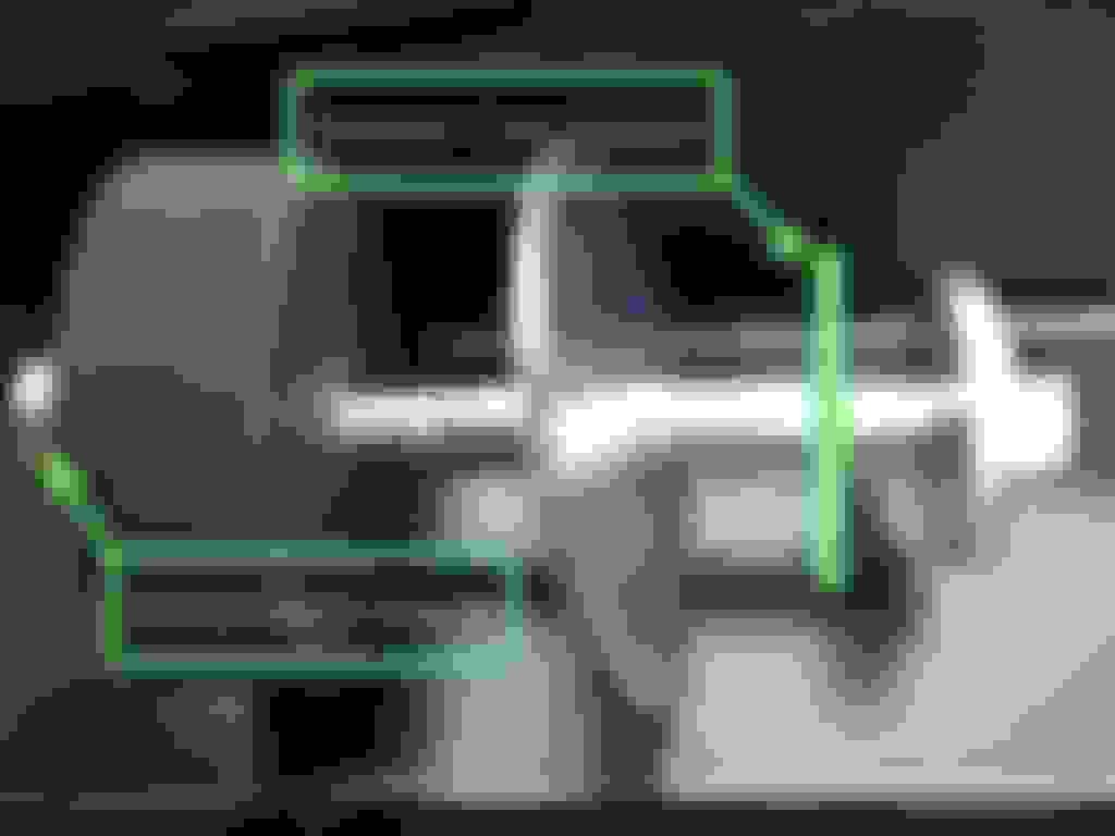
To remove the sector shaft, one has to first center the unit. Using the little white dot painted on the input shaft, I counted four full turns, lock to lock. Centering, then, is two full turns from either locked position. There are three bushing surfaces so a little tapping with a soft hammer or dead blow hammer should be necessary.
As you can see here the three teeth of the sector shaft have to be positioned so as to clear the case without being caught by it. This is why centering the unit first is critical.
There was a little crud in the sector shaft housing so I used PB Blaster and a bottle brush to clear most of it. Several passes of this followed by compressed air seemed to do a pretty good job.
Old versus new. The new USA sourced parts are in the foreground. Although the 1976 Ford Truck Shop Manual describes all sorts of special tools for removing and replacing these parts, I simply used a screwdriver for removal and a large socket for installation. Use lots of lubricant and be sure that the seal lips all point inward. Inner seal (double lip#1), spacer (#2), outer seal (single lip #3) spacer (#4), snap ring.
Note that the new seals on the right have much thicker spacers. My guess is that this is to place the seals at different points on the sector shaft sealing surface so as to make use of the less worn areas.
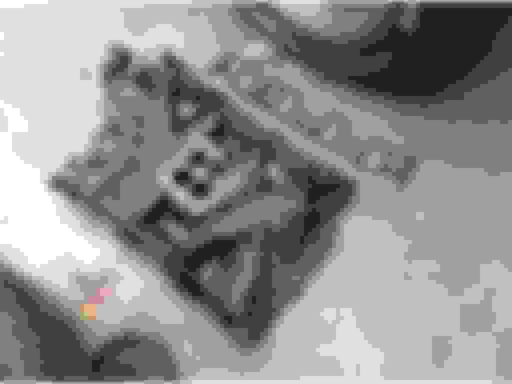
Here is evidence of water intrusion and consequent corrosion right below the snap ring where the outer spacer is located. I�ll be sure to seal this area with paint after reassembly to delay further corrosion.
Here is visual evidence of accumulated crud and wear. I treated all three bearing surfaces with 400 grit wet/dry paper and ATF.
The result looks good from this distance.
Looking closer, its clear that some wear remains but it feels smooth to the touch so will probably be all right.
Reassembled, the area where I found water and dirt intrusion has gotten a heavy coat of paint to add further protection to what the new seals will do.
The unit is ready to be reinstalled. I had some red paint remaining from the calipers so decided to apply the existing color scheme to the steering box as well.
Here it is back on the frame with everything buttoned-up. I used teflon tape on the fittings for the high pressure and return lines of the power steering pump.
Everything seemed to line up correctly. I centered the steering box and set the steering wheel so that the spokes allowed maximum visibility of the dashboard in the wheels straight ahead position. The rag joint slipped onto the input shaft easily and the Pittman arm attached to the end of the sector shaft in the straight ahead position. Attaching the drag link revealed that the wheels were pointed in the right direction.
I needed to figure out a way to prime and test the unit to see if the seals contain the power steering fluid as they ought to. Starting the engine at this point would be a PITA so I devised this simulator. An extra 3/8� hex wrench was modified to fit this half inch drill. So spinning the PS pump while my wife turned the steering wheel back and forth simulated a slow idle. Of course this isn�t a perfect simulation since the fluid level should be checked when hot, the wheels should be on the ground, etc. but I think that the fluid circulated well enough to purge trapped air and reveal any leaks. The good news is that I could find no evidence of leaking anywhere on the power steering unit.
Here�s a close-up of that improvised PS pump driver tool. Once I have the inner fenders and core support back in place, I can run the engine and perform more rigorous testing. Now that the steering unit has passed this simple test, I�ll bleed the brakes, put some grease in all of the Zerk fittings I can find and place cotter keys wherever they are needed. This should wrap-up the suspension and steering repairs so that I can move on to the other �while you�re in there� items.
After replacing the Power Steering (PS) sector shaft seals, priming the unit with fresh, clear PS fluid and simulating low RPM operation, I was unable to detect any further leakage. Overnight, however, the input shaft seal began to leak significantly. There was a good sized puddle waiting for me the next day.
So I yanked the PS unit again, bought an input shaft seal kit (seal, snap ring and dustcover) and installed that. This was a big learning experience. First, I learned that, at a minimum, both sector shaft and input shaft shaft seals should be replaced at the same time. Sealing one simply passes the pressure to the other. Second, I learned that both of these seals can be replaced without disassembling the unit, A screwdriver and snap ring pliers will remove the old units just fine. Cleanup of seal surfaces can be done with wet/dry sandpaper, emery cloth and small wire brushes in a die grinder.
Next, I find a new crack in the frame.
While returning the power steering unit to its proper position, I noticed a very slight �hairline� mark on the driver side frame where the power steering bracket is located. It was only visible because that part of the frame had been wire brushed and painted.
Chasing this hairline with a 3� cutoff disk and applying heat revealed its true extent as shown in the image above.
Of course the collision could have caused this but I�ve also read that a power steering unit can actually exert enough force to tear the frame. Yet another possibility is that I caused this with all of my frame straightening efforts. Or it could have been �all of the above� to one degree or another.
Whatever the cause(s), here it is all welded up. Perhaps now I can start putting this truck back together.
With brakes bled and all Zerk fittings gorged with grease, I started putting things back together. First up are the wheels. Cragar S/S wheels require a spacer in order to clear the front disk brakes on a �76 F series truck but this one-size-fits-all spacer could easily be installed in an eccentric manner. To avoid that, I use Permatex Gasket Maker.
A little dab here and there should do.
A little tape overcomes gravity �
� as do the studs. Once cured, this �gasket should keep the spacer in its proper place as the wheels are replaced. Recall that the PO had used electrical tape to hold the spacer to the wheels. I think that this is a better approach.
Here we see the blue Permatex gasket material holding the spacer in place. In any case, I don�t expect to see any wheel imbalance due to these spacers. Neither do I expect any binding between the wheel lugs and the spacer.
The wheels are on.
The warranty plate from Marti Automotive arrived in the mail. Recall that the warranty tag on the driver side door didn�t match the VIN on the frame. The doors had been swapped out at some time in the past.
Residing in Georgia which is a non-title state for vehicles produced prior to 1985, I felt the very strong need for the VIN on the warranty plate found on the driver side door to match the paper registration. I just couldn�t envision a convincing explanation to offer law enforcement should I be asked to explain the discrepancy.
As it was, the young sheriff�s deputy who documented the frame VIN for me so that I could correct the paper registration could not quite accept the fact that there was no VIN in the cab. He certainly looked very hard for it but ultimately failed.
Soon, everything will be in sync and there will be no vehicular identity crisis.
I am seriously looking forward to reassembly, cranking the engine again and even just driving it around in the yard again.
Reminds me back in college, I worked for a construction company. We were hauling dirt to a free fill spot and got pulled over by a hypo. I was driving a '79 F700 single axle short bed dump truck. No CDL required at that time, he noticed the dirt falling out. He pulled out scales, I didn't know they carried scales. Pulls the scales out and I backed on them. He asked for license and registration. Said, "I noticed you don't have your GVW posted on the side of your truck, or the company name, or your load tarped. You tag is expired, inspection expired (we had them then), you're overloaded and.... this truck comes back stolen."
Huh?!??
Turns out when it was a Hertz rental, it had been wrecked and the door was off a '77 F100 that had apparently been stolen. Thought I was going to jail. He asked where I was taking it, I told him, he said go dump it, take it back to the job site and leave it parked there until this mess is straightened out. YESSIR!!!!
While You�re In There: Removing Heat/AC Plenum & Adding Bling
The PO had removed the A/C compressor as many do when these York units fail. He also bypassed the heater so this huge, useless, plenum intrudes into the engine compartment. If I do add heat and air conditioning, it will be something more modern. Nostalgic Air in Orlando, FL has what look to be some very effective solutions. Adding heat and A/C will be for a future project. Right now, I want to remove that bulky plenum. It won�t be needed with a more modern, compact system.
Removing the plenum leaves a pretty big hole in the firewall. Poking around a restaurant supply house, I found an aluminum pan of the right size. It�s 0.25� thick which is probably more than adequate to plug this hole now and to serve as the bulkhead of a new system in the future.
The first step is to gut the plenum and trim it so that it can be used as a template.
Like so. It�s here that I wish I had a nice bandsaw. I don�t so will use a metal cutting blade mounted in a circular saw.
Here is my crude cutting solution. A sticker on the circular saw specifically warns against doing this so it isn�t recommended. I�ll be doing this again on an upcoming project and hope to get a better aluminum cutting solution in hand before then.
The trick is to cut a little on the fat side so that more precise tools can be used to get the piece down to the line created with the template. It�s always easier to remove material than to add it.
Here is the finished piece after a lot of filing and sanding. Note that the bolt holes are square to help the carriage bolts I will use to stay put during assembly. These started out as round holes that were filed square with a triangular file. The holes in the middle were where the handle to this pan was located. I�ll fill these with a couple of short carriage bolts.
Here it is in place alongside some new chrome valve covers and air cleaner. The air cleaner required a 2� spacer to clear linkage and so on. Good thing these trucks have plenty of space above the carb to work with.
Inside the cab, this view shows the other side of the 1.5� long carriage bolts. The extra length will enable replacing the original ductwork for safe keeping should any part of them be needed in the future.
Here is a close-up of the ducting for fresh air intake. That boot will need to be fastened to the air handler housing better than shown.
Here�s the long view of this area.
So now I am finally ready to start bolting on the radiator core support crossmember, inner fenders and a new radiator. It will be good to hear this thing run again.
The next time you come to the store, bring that AC stuff with you. I will be glad to take it off your hands. I can always use some extra parts for my 75. lol What will you take for it?
I actually ended up torching out the area of my old cab (no A/C hole) for the new cab (has A/C hole) before I tossed the old cab to the steel recycler.
It certainly won't look as fancy as your piece of aluminium, but it should fit just about perfect!
That'll work just as well. I'm still looking for the perfect third party solution.Heat and A/C are musts as I live in sunny Georgia but I'm also keen to get fresh air intake and defrost also and, preferably, using the stock controls or something that looks and operates the same.
I'd be careful with that RTV between the hubs and spacers. It may be cured. but it has not been compressed. I personally wouldn't trust it. Your wheels may feel like they tightened up but, once you start driving it, the RTV will allow the spacers to start walking around and you WILL end up with loose wheels. Like I said..........I wouldn't trust it.
I'd be careful with that RTV between the hubs and spacers. It may be cured. but it has not been compressed. I personally wouldn't trust it. Your wheels may feel like they tightened up but, once you start driving it, the RTV will allow the spacers to start walking around and you WILL end up with loose wheels. Like I said..........I wouldn't trust it.
Thanks for the heads up on that. I'll be sure to check that as soon as I get it running and rolling.
Re the front wheels, one thing I wish I had done was to replace the studs with longer ones to compensate for the thickness of the spacer. It doesn't look as if the PO had done that.
Re-assembly: Radiator Core Support & Inner Fenders
After spending more than a year working on undoing the damage caused by a collision, it�s time to start putting it back together, getting it registered and back on the road as my shop truck. There�s a long line of other projects waiting for attention.
Here is where the �bag and tag� effort pays off. One can forget a lot in a year so this is a great memory enhancer. Recall that each piece was cleaned and painted black before being bagged and tagged. Of course there are some new parts such as the radiator support kit from Dennis Carpenter shown in the foreground.
Here are the inner fenders loosely in place. These tie in to the radiator core support with six bolts on each side.
The radiator core support mounting kit has two rubber biscuits that sandwich the frame providing insulation from vertical movement. This probably results in a longer radiator lifespan.
Here�s the upper part of the radiator core support mounting system. Note the compression sleeve. When installed, this sleeve extends through both rubber biscuits and limits the degree to which they can be compressed. Additional big washers may be needed to adjust the core support and the inner and outer fenders attached to it in an upward direction.
Here it is loosely installed on the passenger side �
� and on the driver side.
The crossmember passes directly under the radiator core support so shouldn�t interfere with the radiator, grille or bumper.
Here it is all tightened down but that is probably just temporary. Certainly, there will be adjustments to be made when fitting the outside fenders and grille that will require loosening up key fasteners. Those would be the three bolts that attach each inner fender to the firewall and the two bolts that attach the radiator core support to the frame.
Next up is reconnecting wires and installing the new radiator. At that point, I should be able to get it running to see if there are any problems that have to be dealt with prior to finishing this up.
Steven@nd, Thanks for the kind words. The '76 Ford Truck Shop Manual weighs in at 2443 pages for the 5 volumes so I probably wouldn't take on the task at this point in life. Nonetheless, someone younger than I should. A digital shop manual (eBook) could offer so much more such as color images, video, animation and so on.
It might be a very profitable venture.
Re-assembly: Radiator, Oil Cooler and Engine Testing
A three core brass/copper radiator was purchased 8/14 mostly because I had the funds at that time and knew from consulting with a reputable radiator shop that the old radiator could�t be re-cored as cost-effectively. What I�ve discovered since then is that brass/copper radiators are being dropped from the inventories of many parts suppliers. Today, I�d probably have to settle for a plastic/aluminum radiator (costs about $100 less), re-coring an old unit or buying one of those all aluminum race-oriented custom units. Thus, I�ll be hanging on to my little collection of old radiators to keep my options open.
The radiator is installed and looks better to me than a plastic/aluminum one.
I�ll do the preliminary engine testing using only the radiator. Then, I�ll add the transmission oil cooler, a Hayden unit I�ve had on the shelf for many years. The primary line will remain connected to the radiator whereas the return line will be re-routed to include the oil cooler attached to the outside of the radiator.
Here are the parts to the Hayden transmission oil cooler. I�m still hunting for a fitting that will give the return line a barbed connector like the ones on the cooler itself. The nice fellow at our local Ace hardware plumbing section was able to concoct a 6� long Rube Goldberg solution with three separate pieces of brass costing over $15. I need to find something more straightforward. For now, it�s time to see if this engine will run and run well.
Here�s a short video of the first running of this engine since repair work started. The first indication of trouble is a clacking sound that can be heard when close to the engine. Exhaust leak? Collapsed lifter? Something else? So here we go down that old rabbit hole.
Since it is so easy to pop the valve covers for a look/see, I start with that. There, I find evidence of water mixing with oil. There�s no oil in the radiator so this looks like a one way street.
Another issue that becomes quickly apparent involves the rocker arm assembly. There are four bolts with one longer than the other three. That longer bolt goes in the second position from the back on the passenger side and the second position from the front on the driver side. This arrangement facilitates the delivery of oil to the rocker arm assembly and, through that, to the push rods and lifters. Instead, the longer bolt on the passenger side was found in the first position and shimmed with a nut to allow tightening. I found no long bolt at all on the driver side! This might be the source of that clacking. I suppose that I should completely disassemble these units and look for damage. I�ve read that the ends are especially susceptible to cracking and breaking.
A cylinder compression test revealed consistent 50 psi dry and 75 psi wet readings. Plug readings were not so consistent. For example, plug 2 (passenger side) is carbon fouled. These were the original plugs and their history is unknown. I probably should have installed new plugs before starting these tests.
In the course of removing the rocker arm assembly on the driver side, I somehow caused the lifter in the frontmost position to pop out and lay down on its side. I could see no way to correct this situation without removing the intake manifold. As it turns out, this was a very fortunate event.
Here I am, ready to lift out the intake manifold. As you can see, this is a unique manifold design in that the push rods go through it and a third of the valve cover is required to cover it.
Here�s the cast iron manifold out of the truck. It is extremely heavy. It was all that I could do to lift it out. I should have used my hydraulic engine lift.
There�s that wayward lifter.
Here�s the serendipity of that lifter forcing me to remove the intake manifold. I should have taken this picture before I went over the gasket mating surface with a scraper. It was clear then that the seal for this water jacket was not performing as designed. Here and at the corresponding point on the other cylinder head was where water appears to have been brought into the oil supply. A poor seal in this area is apparently quite common and thought by many to be due to the use of cork gaskets to seal the back and front of the lifter valley. The thickness of these gaskets may cause a misalignment with the cylinder head just great enough to cause a leak. Use silicone instead they say.
For more detail on this point, see the section entitled �Final Installation� in this DIY Ford piece. (Ford FE Engine Intake Manifolds: The Ultimate Guide)
So I�ve ordered a new aluminum Edelbrock Performer intake manifold, bolts and gaskets. I also sprang for some new MSD ignition parts.
After placing the order, I began to realize what a slippery slope I�m on. From the clean condition of those parts of the heads and block visible to me now, I�m assuming that the PO purchased a remanufactured long block and then bolted on all of the old stuff without a lot of cleaning and with a few serious assembly errors. So, have I got them all or do I need to pull the engine, check the bearings and so on? If I pull the engine, I ought to at least replace the front seal on the C6 tranny but perhaps I ought to yank it too and have it rebuilt to stock specs. Then there�s the question of whether it wouldn�t be a good time to add headers to better match all those performance parts.
You see where this is going? Sure you do. How many here can say, �been there, done that?�
And to think that all this started as a parts truck buy to support the build up of my �76 F-100.

 10-01-2015, 03:11 PM