


wiring help
Thread Starter
|
Laughing Gas


Joined: Jan 2013
Posts: 1,016
Likes: 4
From: Gulf Coast, MS
You have to forgive me I am horrible when looking at diagrams sometimes even though I can read blue prints....From what I can tell all I need to do is find the wire that is in with the voltage regulator wires and find the one that goes to the indicator light on the dash and that hooks in to T1 side of the alternator?
Hotshot


Joined: Mar 2013
Posts: 14,255
Likes: 199
From: Phoenix, Az.
You have to forgive me I am horrible when looking at diagrams sometimes even though I can read blue prints....From what I can tell all I need to do is find the wire that is in with the voltage regulator wires and find the one that goes to the indicator light on the dash and that hooks in to T1 side of the alternator?
Delco SI Alternator 1-Wire vs 3-Wire Explained
Thread Starter
|
Laughing Gas
Joined: Jan 2013
Posts: 1,016
Likes: 4
From: Gulf Coast, MS
Yes. And a jumper wire from Batt terminal to T2. You might go here for more explanation.
Delco SI Alternator 1-Wire vs 3-Wire Explained
Delco SI Alternator 1-Wire vs 3-Wire Explained
Thread Starter
|
Laughing Gas
Joined: Jan 2013
Posts: 1,016
Likes: 4
From: Gulf Coast, MS
After going through all the wiring schematics from 67,68,69,70 and 72 the green and red wire from the voltage regulator seems to be the indicator wire for the alt. but would that be the wire that I connect to the T1 side of the GM alt?
Hotshot
Joined: Mar 2013
Posts: 14,255
Likes: 199
From: Phoenix, Az.
As I recall,yes. In that schematic I posted earlier it is curcuit #904. The far left side of the plug.
Thread Starter
|
Laughing Gas
Joined: Jan 2013
Posts: 1,016
Likes: 4
From: Gulf Coast, MS
Yes sir that is what I was looking at too. Thanks for all the help. Now I need to hurry up and go to sleep so I can get it going right.
Thread Starter
|
Laughing Gas
Joined: Jan 2013
Posts: 1,016
Likes: 4
From: Gulf Coast, MS
Ok I am getting a few conflicting things before I clean this wiring up and wire this right, should the main wire that goes to the batt side of the ALT go directly to the battery or should it go to the hot side of the solenoid and also the same question with the remote sense wire...some articles I have read say these should go directly to battery terminal and some dont so I wanted to get someones opinion.
Logistics Pro
Joined: Nov 2012
Posts: 4,308
Likes: 19
From: Las Vegas, NV

Everything should be on the battery side of the solenoid. In essence, it is a dispersion point for direct battery power.
FTE Stories
Ford Trucks for Ford Truck Enthusiasts

3 Best / 3 Worst Parts of Modern Ford Ownership
Brett Foote
10 Amazing Upgrades That Solve Common Ford Truck Owner Headaches
Pouria Savadkouei
Every 2026 Ford Engine Explained
Brett Foote
10 Ugly Ford Trucks That We Still Kinda Love
Joe Kucinski
10 Things Every Truck Owner NEEDS (2026 Edition)
Michael S. Palmer
Rezvani's Latest Post-Apocalyptic Monster Is a Ford F-150 Raptor Underneath
Verdad Gallardo
Top 10 Most Expensive Ford Trucks Ever Sold on Bring a Trailer
Joe Kucinski
2027 Ford Super Duty Buyer's Guide (Every Model, Engine, & Package)
Brett Foote
Top 10 Ford Truck Tragedies
Joe KucinskiThread Starter
|
Laughing Gas
Joined: Jan 2013
Posts: 1,016
Likes: 4
From: Gulf Coast, MS
Ok thank you for that
Laughing Gas
Joined: Mar 2010
Posts: 1,028
Likes: 5
From: San Francisco East Bay
Maverick, be cautioned that the connection at the voltage regulator is different for idiot lights than it is for gauges. Specifically, they handle the ALT light differently than they do an Ammeter. One only has to be on or off, the other has to be able to show positive current or negative current.
Fordification has schematics for 1970 that show both. IIRC, one is part of the schematic, and the other is shown as an insert on the schematic. Make sure you know which is which, or you could be trying to follow a map that's wrong.
Fordification has schematics for 1970 that show both. IIRC, one is part of the schematic, and the other is shown as an insert on the schematic. Make sure you know which is which, or you could be trying to follow a map that's wrong.
Thread Starter
|
Laughing Gas
Joined: Jan 2013
Posts: 1,016
Likes: 4
From: Gulf Coast, MS
I want to thank everyone for their input and advice....Thipdar I did go back and look at the schematics to make sure that wire was the one I needed to make this all work. Its always good to double and triple check.
This is what I was able to get rid of....

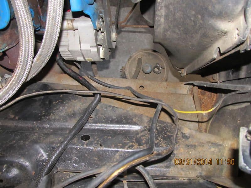
This is the after shot of my wiring job, still have all the battery cables to replace but its a start.

This is what I was able to get rid of....
This is the after shot of my wiring job, still have all the battery cables to replace but its a start.

Laughing Gas
Joined: Mar 2010
Posts: 1,028
Likes: 5
From: San Francisco East Bay
I want to thank everyone for their input and advice....Thipdar I did go back and look at the schematics to make sure that wire was the one I needed to make this all work. Its always good to double and triple check.
This is the after shot of my wiring job, still have all the battery cables to replace but its a start.
This is the after shot of my wiring job, still have all the battery cables to replace but its a start.
Your Positive battery cable should be RED. When you do replace your battery cables, please make sure you get a red one and a black one.
We were at an anti-narcotics checkpoint on Federal Highway 2. The caballero I was trying to help needed to jump-start his Mustang. The top of his battery had melted to slag (yes, it gets THAT hot in the Sonora Desert) and we couldn't read the plus or minus marks that are normally molded into the top of the battery. He was delighted that I had jumper cables and wanted to make it easy for me. I wanted to double check the connection, and said "Momentito!", but he went on hooking things up.
I winced and plugged my ears with my fingers... and the Federale looked at me like "What is this crazy gringo doing?", until he heard the "SNAP!" from the final connection. Sure enough, the caballero had hooked the jumper cables up backwards.
The Federale let out a machinegun-rapid burst of spanish, of which I caught two words: one was "estupido", and the other was "negro" ("black", 'cuz he'd switched the yellow and black jumper cable connectors).
You can bet that the caballero was R-E-A-L cautious when he hooked it up the second time.
Fortunately, there wasn't much damage. One of the battery cable connectors melted a little bit (part of it turned to molten lead from the arc), but I still got years of use out of it.
Anyway, it'd be a good thing if you could swap out the black positive cable for a red one... having two black battery cables is hazardous.