


EGR issues
Posting Guru
Joined: May 2013
Posts: 1,122
Likes: 0
From: Haysville, KS
EGR Clarification:
Ported Vacuum Source to Ported Thermal Switch Input.
Ported Thermal Switch Output to EGR Valve
Engine not above idle - no ported vacuum - EGR closed
Engine above idle but cold - switch closed, no vacuum at EGR - EGR Closed
Engine not above idle but warm - ported switch open but no source vacuum - EGR Closed
Engine above idle and engine warm - ported vacuum available at switch, switch open - EGR Activated (open)
Pretty simple..
With computer control, the computer used a solenoid instead of the thermal ported switch. Computer opened solenoid when above idle and at operating temperature.
EVAP was controlled by computer via two solenoids (one at PCV, one at bowl vent) and a thermal one-way valve.
I can go into an explanation of that system but don't want to hijack

pedant
Joined: Jan 2008
Posts: 23,576
Likes: 40
From: EXTREME southwest CT

That's all fine for a computer controlled engine...
What I don't understand in the linked diagram, why at WOT?
You want EGR in cruise where cylinder filling is poor and vacuum advance is high.
What I don't understand in the linked diagram, why at WOT?
You want EGR in cruise where cylinder filling is poor and vacuum advance is high.
Posting Guru
Joined: May 2013
Posts: 1,122
Likes: 0
From: Haysville, KS
The system will open the EGR when above idle. It will provide more at WOT, but ported vacuum is there at any speed above idle in varying degrees.
It's really not rocket science - ported vacuum is only available when the throttle plate is not closed - above idle speed. The switch only allows that vacuum to the EGR when the engine is warm. So - above idle, warm - EGR enabled.
Simple terms - driving and warm - EGR, sitting still at idle speed - no EGR
pedant
Joined: Jan 2008
Posts: 23,576
Likes: 40
From: EXTREME southwest CT
I understand the concept,(AND the practice) believe me.
I don't understand the above diagram with no temperature control and ported at WOT only.
Screw this , I'm on a mission now to find the proper diagram for a 1980 4.9
I don't understand the above diagram with no temperature control and ported at WOT only.
Screw this , I'm on a mission now to find the proper diagram for a 1980 4.9
Posting Guru
Joined: May 2013
Posts: 1,122
Likes: 0
From: Haysville, KS
Didn't mean to ruffle feathers. The diagram posted is for a computer controlled engine. The WOT is simply a solenoid that opens when above idle. There is a hard vacuum line going from the egr to that solenoid.
In the non-computer version, you should have a thermal ported switch, most likely in the heater hose elbow at the front of the engine. One side will go to the EGR (may also T off to the EVAP purge) and the other will go to a ported vacuum source.
If you can't find a diagram, just look for that ported switch and trace / connect the lines.
For a non-computer engine:
Overall, you'll have a large manifold vacuum line to the power brake booster (if equipped). Also manifold vacuum to the PCV valve, with perhaps a second smaller line from the PCV valve to EVAP canister purge.
A vacuum line may also go to the thermal valve in the air cleaner
Ported vacuum will go to the ported vacuum switch and then to the EGR and, most likely, the EVAP purge valve
If you have a SMOG pump, there may be lines to that; mine was computer controlled and is gone so i don't have much info on the non-computer version (if it exists)
My whole point was to not get overwhelmed and bogged down. If you suspect an EGR issue, it's easy to diagnose. Vacuum pump to test the valve if needed, a finger to test vacuum and knowing where the vacuum lines should go.
I don't have a diagram to post but would if I could..
Laughing Gas


Joined: Apr 2013
Posts: 1,049
Likes: 65
I hope the original poster will chime back in and let us know how they're doing. Beyond all the theory I think KSCop's advice is most practical.
In the mean time please let me take advantage of the panel of experts assembled here to ask about my truck. I assumed my distributor advance would be ported vacuum, but looking at my vacuum diagram I'm not so sure. What do you think, ported or not?

Moderator


Joined: Nov 2007
Posts: 22,415
Likes: 92
From: Denver Metro Area, CO

It's quite easy to be misled on the Internet, lots of people talkin' out their *** like they're experts but with no verifiable & credible sources to back them up.
Hence, official literature ALWAYS helps the credibility.
One of the reasons why you don't see much such literature about emissions controls is because of the numerous different configurations Ford had - literally HUNDREDS of what they call Calibration Codes. High Altitude, 4x4, Air Conditioning, California, what engine and what transmission, those were the major things affecting what calibration any individual truck came with.
These were the early & dark years of emissions controls with detuned engines and sometimes brute-force ugly things done to meet EPA requirements. Yet I am amazed at what Detroit came up with using only vacuum and temperature... these things ran beautifully when they were new...
Posting Guru
Joined: May 2013
Posts: 1,122
Likes: 0
From: Haysville, KS
Good point about all the calibrations. The theory still still applies and if you understand it, you can figure out any of them. I have diagrams from my '85 but it was computer controlled and won't help. It's been converted to vacuum control per the earlier models and is MUCH simpler now.
I'm offering what I know to be true on my vehicles and others I've worked on. Trust me; understand what it does and how it's supposed to work and you'll figure it out. No diagram in the world will really help unless you understand what it means. You don't need an advanced degree to understand EGR, EVAP, etc. It's not magic and is really a pretty simple concept. Even the computer controlled ones follow the same theory; just controlled a bit differently (a whole other conversation)
To answer the other question; the vacuum advance has to be controlled in some way so it only advances at higher RPM. Ported vacuum will accomplish this, but so will a computer controlled vacuum valve. In the case of the computer control, in theory it could have manifold vacuum at the source, as the computer controlled valve would only allow it to apply the vacuum at the correct time. Now I'm not the best at reading diagrams (most vehicles I've restored don't have one and I need to trace lines and make my own..) it APPEARS to me that your distributor is connected to a vacuum control valve that uses manifold vacuum as it's source. That tells me that the valve functions to only allow vacuum at the distributor at the correct time. It appears that that valve or solenoid is also working with the EVAP system and perhaps smog pump. The computer can in this way control the curve. If the computer and sensors feeding it are all good and if the control valves are all good, this is a great idea. If any of those components go bad, well that aint' so great.
But don't listen to me - trace the lines and see if it makes sense. (bet it does though.. LOL)
Mechanical advance uses weights and springs to accomplish the same thing; centrifugal force / engine RPM causes the advance. Same idea, different method.
Again - it comes down to understanding the design / function and you can figure stuff out.
I agree there is a lot of misinformation out there and I don't swallow any of it whole without verifying it for myself. That's what I've done and that's what I post.
That's why I love my '63 - NO EGR, NO EVAP, NO SMOG PUMP.. simple simple simple.
Then I got my '85 and it's EGR, EVAP, SMOG, COMPUTER. Guess what - it's don't have that no more -- EGR / EVAP Vacuum controlled (as in my description and works just as designed). Smog pump long gone..
But I digress..
FTE Stories
Ford Trucks for Ford Truck Enthusiasts

3 Best / 3 Worst Parts of Modern Ford Ownership
Brett Foote
10 Amazing Upgrades That Solve Common Ford Truck Owner Headaches
Pouria Savadkouei
Every 2026 Ford Engine Explained
Brett Foote
10 Ugly Ford Trucks That We Still Kinda Love
Joe Kucinski
10 Things Every Truck Owner NEEDS (2026 Edition)
Michael S. Palmer
Rezvani's Latest Post-Apocalyptic Monster Is a Ford F-150 Raptor Underneath
Verdad Gallardo
Top 10 Most Expensive Ford Trucks Ever Sold on Bring a Trailer
Joe Kucinski
2027 Ford Super Duty Buyer's Guide (Every Model, Engine, & Package)
Brett Foote
Top 10 Ford Truck Tragedies
Joe Kucinski
Cross-Country
Joined: Mar 2013
Posts: 52
Likes: 0
The WOT is bolted to the carb up front. It has a vacuum line between the Carb and Egr valve. It dumps or creates a vacuum leak to to disable egr under hard acceleration. The link below has more links with more info. There is a carb on ebay with front picture showing the WOT. Below the bowl vent
http://www.ebay.com/itm/NOS-1983-MOTORCRAFT-CARTER-1-BARREL-CARBURETOR-2-3L-140-CU-IN-E3TE-BRA-7595S-/271342683676?pt=Motors_Car_Truck_Parts_Accessories&hash=item3f2d48c61c&vxp=mtr
https://www.ford-trucks.com/forums/1...er-yf-wot.html
This thread has really good info. I would add that my BWD egr valve came with a metering insert to be installed first.
Posting Guru
Joined: May 2013
Posts: 1,122
Likes: 0
From: Haysville, KS
As I said.. computer controlled valve that controls vacuum to the EGR
That's why if you ever do a conversion and get rid of the computer and feedback carb, and want to keep the EGR, you need to convert it to the old school method - ported vacuum switch..
Same theory of operation...
When you think about it, the folks that designed all this were pretty clever...
BTW, I DO have all the manuals (emissions, electrical, body, chassis, electrical, etc.) for the 1985...
Laughing Gas
Joined: Apr 2013
Posts: 1,049
Likes: 65
Thanks guys.
KsCop, surprisingly my stock '87 doesn't have a computer, aside from the duraspark module.
In my case I think the vacuum advance is really more about mileage than performance.
Somewhere along the line I got the idea my vacuum advance worked in tandem with the ERG, advancing the timing when the EGR is open under light throttle to improve gas mileage. However, under heavy throttle conditions both the ERG and distributor vacuum goes away. Thus, with the ERG closed, the intake charge is no longer diluted with exhaust gases and becomes a more power mix of just air and gas. At the same time the timing is retarded to eliminate ping. Then, once the RPM's are high enough, the mechanical advance comes in.
And speaking of RPM's, It seems the way I'm set up there's little point in going over 3500. Beyond that all it makes is noise. All the power is back at 2300 - 3200.
I suppose it's just like ctubutis said, because of all the variables what's true for me may not be exactly true for you...or vice verse...or something.
Anyway, I sure hope the original poster doesn't mind us keeping the thread warm for them!
Happy (almost) New Year!
Posting Guru
Joined: May 2013
Posts: 1,122
Likes: 0
From: Haysville, KS
Lots of variation among vehicles; Ford was especially good at that..
Everything is exactly the same except for sometimes..
My '85 had the TFI Ignition and computer, and a place for the crank sensor but no crank sensor. It now has a DUI ignition, non-feedback carburetor and no computer. And the space for the crank sensor makes a dandy TDC locator..
My '63 is a mix of parts and years (1957 to 1963) and that is from the factory - they use stuff up until it's gone then transition it appears. Throw in the variations from state to state and things get even more interesting.
But then. I have no credentials to back up what I say and am evidently talking out my ***.
Funny story about experts though: The VIN on my titled, original paperwork 1963 F100 indicates, according to an "expert' based on the VIN there is no way my '63 is a '63 as it was made two months before the model year started. The expert wasn't even alive in '63 so I doubt he could have been there when they moved things up that year...
Always the same except for sometimes..
ROFL
Laughing Gas
Joined: Apr 2013
Posts: 1,049
Likes: 65
All in good fun. My wife has an '05 Pacifica too. How's your oil consumption? Maybe 1000 miles per quart here.
As for speaking with authority on my particular vacuum diagram? I don't think that's possible. It's an unsolvable riddle. Ranks right up there with the classic "what is the sound of one hand clapping?" or "If a man walks alone into the forest, and there is no woman there to see him, is he still wrong?" (the wife loves it when I ask her this. LOL)
It's a good thing I got an extra, identical and complete, vacuum line assembly from the junkyard to spread upon the workbench and contemplate. Tracing those vacuum lines in a van chassis is a bit of a challenge.
pedant
Joined: Jan 2008
Posts: 23,576
Likes: 40
From: EXTREME southwest CT
That's what I love about this place. LEARNING and the quest for knowledge. Not only how to fix something but also why things work the way they do.
I hope the original poster will chime back in and let us know how they're doing. Beyond all the theory I think KSCop's advice is most practical.
Basically there should be no vacuum to the egr at idle and the egr should only have vacuum while cruising at operating temperature.
In the mean time please let me take advantage of the panel of experts assembled here to ask about my truck. I assumed my distributor advance would be ported vacuum, but looking at my vacuum diagram I'm not so sure. What do you think, ported or not?
Your routing diagram is much the same as mine. **C JB**
I'm not sure the calibration code in the lower left is the same because you don't show that half of the sticker.
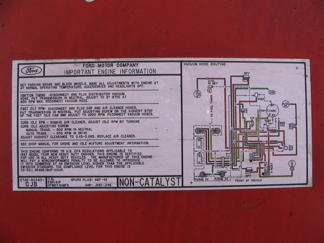
There is restricted manifold vacuum present at closed throttle.
Ford set up many of their vehicles this way.
Do you see the little "V-REST" just off the VCV?
That is a plastic orifice inserted in the vacuum line.
When the truck starts to overheat the Vacuum Control Valve shifts to the unrestricted manifold vacuum, pulling in more timing and increasing idle speed (and waterpump/fan speed)
These little bits of plastic come in different colors depending on the size of the hole in them. (mine is bright blue)
So far I haven't found a vacuum routing diagram for a 1980.
But I will keep looking.
Maybe the OP will post a picture of theirs?
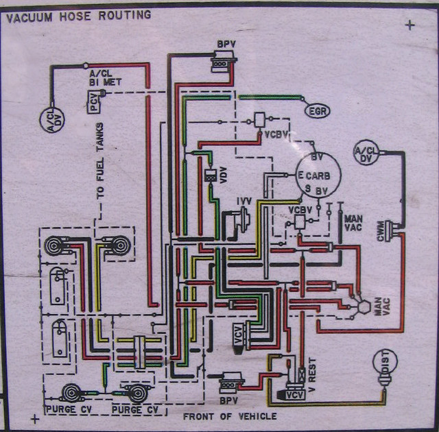
All the -many- computer controlled vacuum diagrams I have seen so far clearly show the (3)solenoids lined up on the drivers side of the valve cover.
They are graphical representations with components in the correct relationship to each other.
Colors indicate source or function.
Red= Manifold Vacuum.
Green= EGR and some emissions.
Black= AIR control or -in some cases- rubber lines
White= Ported
There is a post in the stickies by AsianSpanker that acts as a glossary.
Last edited by ArdWrknTrk; Jan 1, 2014 at 02:04 AM. Reason: Add pics of my sticker, and some info about colors.
Posting Guru
Joined: May 2013
Posts: 1,122
Likes: 0
From: Haysville, KS
Pacifica isn't bad on oil, but it has an ABS light on and a clunk in the front end..
It's next in the shop once I get the 85 F150 out to make room for it. I'll need to drive the F150 so my wife can drive the van so I can have time to work on her Pacifica!
Going to replace ABS sensors and lower control arm bushings.. fun fun fun
hijack complete..
It's next in the shop once I get the 85 F150 out to make room for it. I'll need to drive the F150 so my wife can drive the van so I can have time to work on her Pacifica!
Going to replace ABS sensors and lower control arm bushings.. fun fun fun
hijack complete..