


Burning up generators
Thread Starter
|
Junior User
Joined: Apr 2008
Posts: 70
Likes: 0
Burning up generators
Not sure what is going on here but my '05 F-350 6.0L is eating up generators like a kid in a candy store. Last one didn't even last a month. Previous one lasted 6 months.
I'm suspecting something in the charging system isn't right. Anyone have any experience with this type of problem?
I'm suspecting something in the charging system isn't right. Anyone have any experience with this type of problem?
Hotshot


Joined: Apr 2010
Posts: 19,072
Likes: 242
From: Saratoga Springs,UT
Cargo Master
Joined: May 2006
Posts: 2,116
Likes: 6
From: Florida

Without knowing anything else I would recommend checking all your cables and connections, as well as the batteries. Loose connections will kill them quickly. I have witness them literally catch fire.

Posting Guru
Joined: Jun 2006
Posts: 1,590
Likes: 0
What alternator are you putting on your truck? Advance Auto? Auto Zone? O'Reilly? OEM Motorcraft? Remanufactured or New?
1. What is your battery Voltage with the Engine Off?
2. What is your battery Voltage with the Engine Running?
3. Is your Charging System Warning Indicator On?
1. What is your battery Voltage with the Engine Off?
2. What is your battery Voltage with the Engine Running?
3. Is your Charging System Warning Indicator On?
Thread Starter
|
Junior User
Joined: Apr 2008
Posts: 70
Likes: 0
What alternator are you putting on your truck? Advance Auto? Auto Zone? O'Reilly? OEM Motorcraft? Remanufactured or New?
1. What is your battery Voltage with the Engine Off?
2. What is your battery Voltage with the Engine Running?
3. Is your Charging System Warning Indicator On?
1. What is your battery Voltage with the Engine Off?
2. What is your battery Voltage with the Engine Running?
3. Is your Charging System Warning Indicator On?
Battery voltage is 15.5 with the engine off. I know that is too high.
With engine running voltage is 11.7 and stays around 12 until the engine is at temp and then goes to 13.9
The charging system light is on and we have the generator 1 code.
Posting Guru
Joined: Jun 2006
Posts: 1,590
Likes: 0
The first one I put in was an AutoZone, second one was a Remy brand.
Battery voltage is 15.5 with the engine off. I know that is too high.
With engine running voltage is 11.7 and stays around 12 until the engine is at temp and then goes to 13.9
The charging system light is on and we have the generator 1 code.
Battery voltage is 15.5 with the engine off. I know that is too high.
With engine running voltage is 11.7 and stays around 12 until the engine is at temp and then goes to 13.9
The charging system light is on and we have the generator 1 code.
P0620 Dual generator upper fault detected
P0623 Dual generator battery lamp circuit fault detected
P1148 Dual generator lower fault detected
P1149 Dual generator lower circuit fault detected
P1397 System voltage out of self-test range
Trending Topics

New User
Joined: Aug 2013
Posts: 20
Likes: 0
Did you do any modifications? Like running a new power and ground off the alternator to the secondary battery? This helps level out the spikes and saves the systems a bit. More talk of doing this on ficmrepair.com
FTE Stories
Ford Trucks for Ford Truck Enthusiasts

Top 10 Fords at 2026 Carlisle Ford Nationals
Joe Kucinski
3 Best / 3 Worst Parts of Modern Ford Ownership
Brett Foote
10 Amazing Upgrades That Solve Common Ford Truck Owner Headaches
Pouria Savadkouei
Every 2026 Ford Engine Explained
Brett Foote
10 Ugly Ford Trucks That We Still Kinda Love
Joe Kucinski
10 Things Every Truck Owner NEEDS (2026 Edition)
Michael S. Palmer
Rezvani's Latest Post-Apocalyptic Monster Is a Ford F-150 Raptor Underneath
Verdad Gallardo
Top 10 Most Expensive Ford Trucks Ever Sold on Bring a Trailer
Joe Kucinski
2027 Ford Super Duty Buyer's Guide (Every Model, Engine, & Package)
Brett FooteHotshot
Joined: Apr 2010
Posts: 19,072
Likes: 242
From: Saratoga Springs,UT
that's wild is the Battery BOILING LOL
A Battery is Considered Fulley Charged at 12.68volts
First Iv seen a Float charge High like this
Make shure Both ground cables have good conections off the battery follow to frame and engine Mounts
What DTC
Hotshot
Joined: Apr 2010
Posts: 19,072
Likes: 242
From: Saratoga Springs,UT
I think the Guys have found a few other Good Solutions for High Output Alt
Idealy the More Amps you get the Better the truck does But also you want quality so you don't have to worrey about things Like FICMs and Short Life Alternator unit that stresses all the Trucks electronics Fast each time they Die
Idealy the More Amps you get the Better the truck does But also you want quality so you don't have to worrey about things Like FICMs and Short Life Alternator unit that stresses all the Trucks electronics Fast each time they Die
Posting Guru
Joined: Jun 2006
Posts: 1,590
Likes: 0
If you can answer the questions I posted, I'm reading directly from the shop manual. If you want to find the solution, there are steps to follow. If you don't have dual alternators then the questions I have asked don't pertain to you.
Thread Starter
|
Junior User
Joined: Apr 2008
Posts: 70
Likes: 0
I do have the dual alternators.
The codes are:
P0620 Dual generator upper fault detected
P1148 Dual generator lower fault detected
Posting Guru
Joined: Jun 2006
Posts: 1,590
Likes: 0
First thing you want to do is disconnect the Batteries and have them tested at an Auto Parts store. Have them tested 1 at a time on their machine and have them replaced with known good batteries if they fail (likely failed batteries if you have 15.5 volts with engine off) or all of these tests below may be worthless.
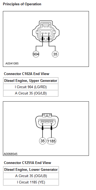
Functionality
With the key in the ON position (dual generator system), voltage is supplied by the powertrain control module (PCM)-controlled I circuit 1183 (WH/YE) / 904 (LG/RD) to the upper generator and through the I circuit 1185 (YE) to the lower generator. If the glow plug system is not cycling, the PCM maintains power to the lower generator. If the glow plug system is cycling, the PCM supplies power to the lower generator momentarily to verify there is a volt drop, then shuts off the power on the lower generator I circuit 1185 (YE). Once the glow plug system stops cycling, the PCM supplies power on the lower generator I circuit 1185 (YE), which turns the regulator on allowing current to flow from the battery sense A circuit to the generator field coil, at which time it begins to function normally. The PCM maintains power on the upper generator I circuit 1183 (WH/YE) / 904 (LG/RD), which turns on the regulator, allowing current to flow from the battery sense A circuit to the generator field coil.
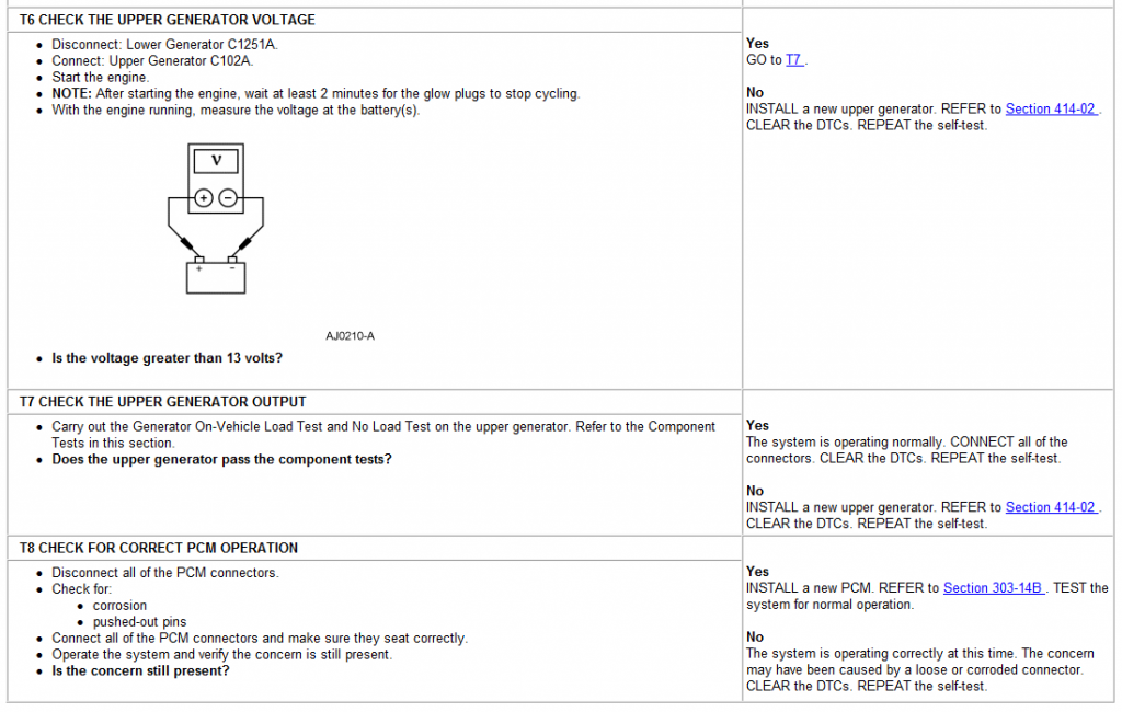
Once the generator begins generating current, a voltage signal is taken from the generator stator and fed back to the regulator internally. This voltage feedback signal (typically one-half of the battery voltage) is used by the PCM to turn off the charging system warning indicator.
With the system functioning normally, the generator output current is determined by the voltage of the A circuit 35 (OG/LB). The A circuit 35 (OG/LB) voltage is compared to a set voltage internal to the regulator, and the regulator controls the generator field current to maintain the correct generator output.
The set voltage varies with temperature and is typically higher in cold temperatures and lower in warm temperatures. This allows for more efficient battery recharge in the winter and reduces the chance of overcharging in the summer.
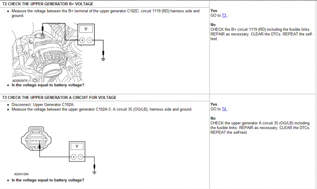
Positive Battery Output (B+) Circuit 1119 (RD) (Upper) / Circuit 36 (YE/WH) (Lower)
The generator output is supplied through the positive battery output (B+) terminal on the rear of the generator to the battery and the electrical system.
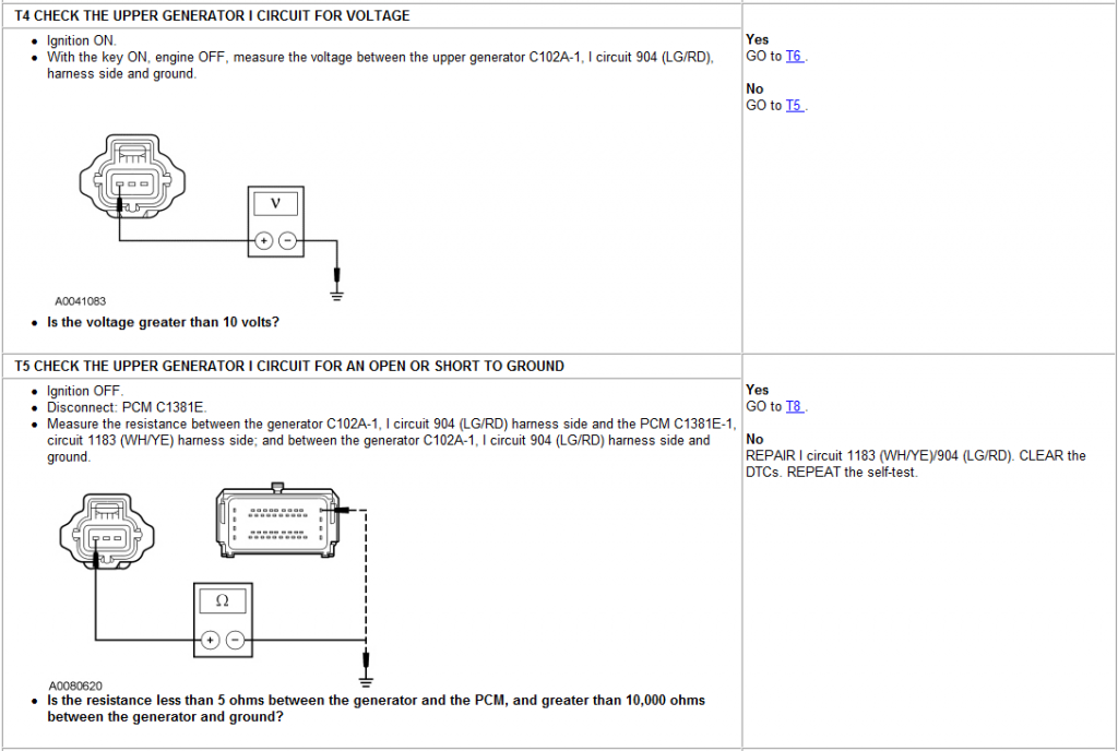
I Circuit � Dual Generator
The I (ignition) circuit is used to turn on the voltage regulator(s). This circuit is powered up when the key is in the ON position. When the PCM detects key ON, the PCM provides power to the upper generator I circuit 1183 (WH/YE) / 904 (LG/RD) and also to the lower generator I circuit 1185 (YE). The power to the lower generator is only momentary unless the glow plug system is not cycling. Once the glow plugs stop cycling, the PCM provides constant power on the lower generator I circuit 1185 (YE).
A Circuit 35 (OG/LB)
The A circuit or battery sense circuit is used to sense battery voltage. This voltage is used by the regulator to determine generator output.
Inspection and Verification
WARNING: Batteries contain sulfuric acid. Avoid contact with skin, eyes, or clothing. Also, shield your eyes when working near batteries to protect against possible splashing of the acid solution. In case of acid contact with skin or eyes, flush immediately with water for a minimum of 15 minutes and get prompt medical attention. If acid is swallowed, call a physician immediately. Failure to follow these instructions may result in personal injury.
WARNING: Batteries normally produce explosive gases. Therefore, do not allow flames, sparks or lighted substances to come near the battery. When charging or working near a battery, always shield your face and protect your eyes. Always provide ventilation. Failure to follow these instructions may result in personal injury.
WARNING: When lifting a battery, excessive pressure on the end walls could cause acid to spew through the vent caps, resulting in personal injury, damage to the vehicle or battery. Lift with a battery carrier or with your hands on opposite corners. Failure to follow these instructions may result in personal injury.
NOTICE: Do not make jumper connections except as directed. Incorrect connections may damage the voltage regulator test terminals, fuses, or fusible links.
NOTICE: Do not allow any metal object to come in contact with the generator housing and internal diode cooling fins. A short circuit may result and burn out the diodes.
NOTE: While carrying out any pinpoint test, disregard the diagnostic trouble codes (DTCs) set while following the specific pinpoint test. After the completion of any test, be sure to clear all DTCs in the PCM.
NOTE: All voltage measurements are referenced to the negative (-) battery post unless otherwise specified.
NOTE: The dual generator I circuit/bulb circuit 4-way connector MUST be connected before disconnecting or connecting the battery. The PCM relearns its parameters every time it is disconnected and connected to power. Failure to follow this procedure causes the PCM to misinterpret the charging system as a single generator system, causing loss of DTC capability and control.
Once you've reached this step, let me know I'll upload more pinpoint tests.
Functionality
With the key in the ON position (dual generator system), voltage is supplied by the powertrain control module (PCM)-controlled I circuit 1183 (WH/YE) / 904 (LG/RD) to the upper generator and through the I circuit 1185 (YE) to the lower generator. If the glow plug system is not cycling, the PCM maintains power to the lower generator. If the glow plug system is cycling, the PCM supplies power to the lower generator momentarily to verify there is a volt drop, then shuts off the power on the lower generator I circuit 1185 (YE). Once the glow plug system stops cycling, the PCM supplies power on the lower generator I circuit 1185 (YE), which turns the regulator on allowing current to flow from the battery sense A circuit to the generator field coil, at which time it begins to function normally. The PCM maintains power on the upper generator I circuit 1183 (WH/YE) / 904 (LG/RD), which turns on the regulator, allowing current to flow from the battery sense A circuit to the generator field coil.
Once the generator begins generating current, a voltage signal is taken from the generator stator and fed back to the regulator internally. This voltage feedback signal (typically one-half of the battery voltage) is used by the PCM to turn off the charging system warning indicator.
With the system functioning normally, the generator output current is determined by the voltage of the A circuit 35 (OG/LB). The A circuit 35 (OG/LB) voltage is compared to a set voltage internal to the regulator, and the regulator controls the generator field current to maintain the correct generator output.
The set voltage varies with temperature and is typically higher in cold temperatures and lower in warm temperatures. This allows for more efficient battery recharge in the winter and reduces the chance of overcharging in the summer.
Positive Battery Output (B+) Circuit 1119 (RD) (Upper) / Circuit 36 (YE/WH) (Lower)
The generator output is supplied through the positive battery output (B+) terminal on the rear of the generator to the battery and the electrical system.
I Circuit � Dual Generator
The I (ignition) circuit is used to turn on the voltage regulator(s). This circuit is powered up when the key is in the ON position. When the PCM detects key ON, the PCM provides power to the upper generator I circuit 1183 (WH/YE) / 904 (LG/RD) and also to the lower generator I circuit 1185 (YE). The power to the lower generator is only momentary unless the glow plug system is not cycling. Once the glow plugs stop cycling, the PCM provides constant power on the lower generator I circuit 1185 (YE).
A Circuit 35 (OG/LB)
The A circuit or battery sense circuit is used to sense battery voltage. This voltage is used by the regulator to determine generator output.
Inspection and Verification
WARNING: Batteries contain sulfuric acid. Avoid contact with skin, eyes, or clothing. Also, shield your eyes when working near batteries to protect against possible splashing of the acid solution. In case of acid contact with skin or eyes, flush immediately with water for a minimum of 15 minutes and get prompt medical attention. If acid is swallowed, call a physician immediately. Failure to follow these instructions may result in personal injury.
WARNING: Batteries normally produce explosive gases. Therefore, do not allow flames, sparks or lighted substances to come near the battery. When charging or working near a battery, always shield your face and protect your eyes. Always provide ventilation. Failure to follow these instructions may result in personal injury.
WARNING: When lifting a battery, excessive pressure on the end walls could cause acid to spew through the vent caps, resulting in personal injury, damage to the vehicle or battery. Lift with a battery carrier or with your hands on opposite corners. Failure to follow these instructions may result in personal injury.
NOTICE: Do not make jumper connections except as directed. Incorrect connections may damage the voltage regulator test terminals, fuses, or fusible links.
NOTICE: Do not allow any metal object to come in contact with the generator housing and internal diode cooling fins. A short circuit may result and burn out the diodes.
NOTE: While carrying out any pinpoint test, disregard the diagnostic trouble codes (DTCs) set while following the specific pinpoint test. After the completion of any test, be sure to clear all DTCs in the PCM.
NOTE: All voltage measurements are referenced to the negative (-) battery post unless otherwise specified.
NOTE: The dual generator I circuit/bulb circuit 4-way connector MUST be connected before disconnecting or connecting the battery. The PCM relearns its parameters every time it is disconnected and connected to power. Failure to follow this procedure causes the PCM to misinterpret the charging system as a single generator system, causing loss of DTC capability and control.
Once you've reached this step, let me know I'll upload more pinpoint tests.
Posting Guru
Joined: Jun 2006
Posts: 1,590
Likes: 0
That's not the one that comes free in the flyers is it? Get rid of that thing! lol