Project: he351ve turbo
#61
 09-26-2012, 12:27 AM


The only reason lil red sled and I chose these over 6.0 turbos was because the actuall adjustment function appears to be more complex...some sort of controller needed. So we figured we'd look for these and turns out he has shelfs full of these at work.
The actual wheels of this turbo are relatively small so might not be best for "big" power but with the Vgt I'm hoping its a nice step up for just all around...with a good functioning adjustment for the leaver of course
The actual wheels of this turbo are relatively small so might not be best for "big" power but with the Vgt I'm hoping its a nice step up for just all around...with a good functioning adjustment for the leaver of course
#63
09-26-2012, 07:11 AM
Posting Guru
Join Date: Sep 2008
Location: On the prairie
Posts: 1,840
Likes: 0
Received 0 Likes
on
0 Posts
#64
09-26-2012, 08:46 AM
That can be an issue due to the spring not opening linearly. This is more of a problem when the vanes slam shut as that happening can cause the turbo to bark. One way to prevent the turbo from being destroyed over time due to turbo bark is to actually add a blowoff valve. Another method that could work as well is either using a double acting air cylinder run off drive pressure to open it and a regulated amount of boost to close it. I plan on using a boost controller to bleed off the pressure so that the drive pressure overpowers the boost slightly to open the vanes. Another way would be to use a single acting air cylinder. One side is controlled off boost or drive pressure and the opposing side is a spring in the cylinder. Do some research. There is actually a lot of info out there on these types of setups.
#65
09-26-2012, 10:46 AM
Senior User
Join Date: Jul 2008
Location: Foothills of cascades
Posts: 213
Likes: 0
Received 0 Likes
on
0 Posts
#66
10-01-2012, 08:12 PM
Originally Posted by 91dirtydiesel;12302260[IMG
http://i1095.photobucket.com/albums/i463/91dirtydiesel/4AE35784-B792-442D-B0F7-9FCB6BEAEE5E-2774-00000284450D17E4_zps9dd21521.jpg[/IMG]
#67
10-01-2012, 11:00 PM
Join Date: Nov 2008
Location: Buckley, WA
Posts: 2,851
Likes: 0
Received 0 Likes
on
0 Posts
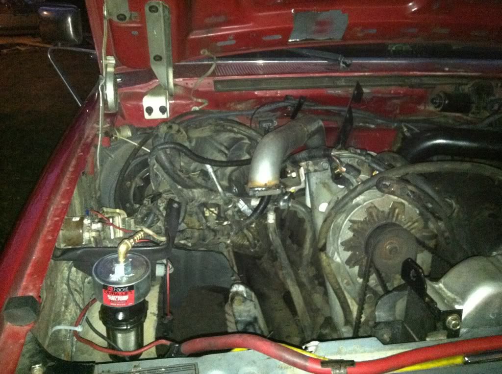
had to clock the turbine side again...will be running exhaust through the engine bay...should be much easier. ill coat it and wrap it all so it keeps the heat somewhat contained.
the holset has a "t4i" flange and i diddnt feel like payin 40$ for a flange so i picked up a 8$ T3 flange and cut the corners off so the studs/bolts would fit.
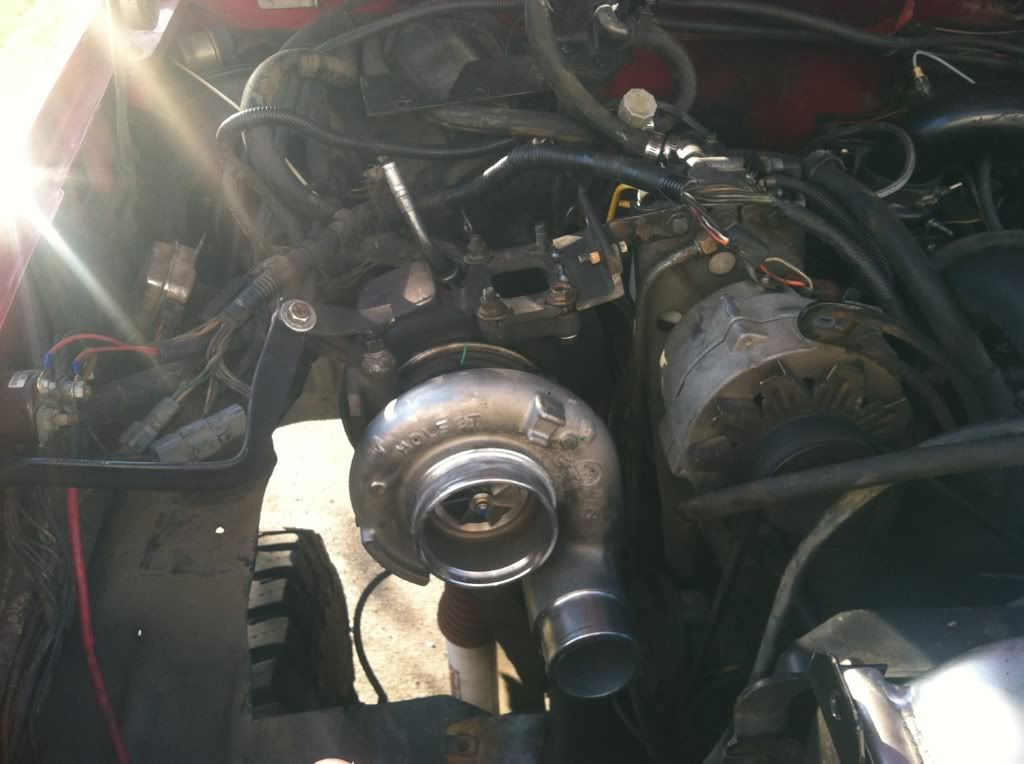
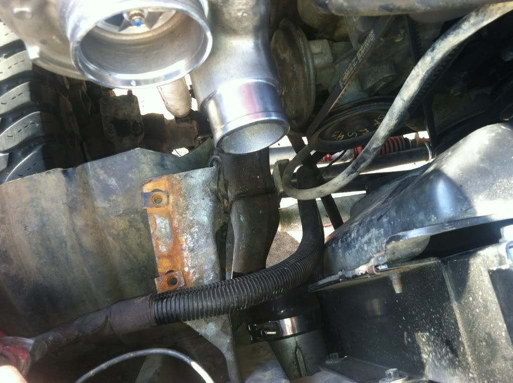
should be pretty east to run into IC from this location
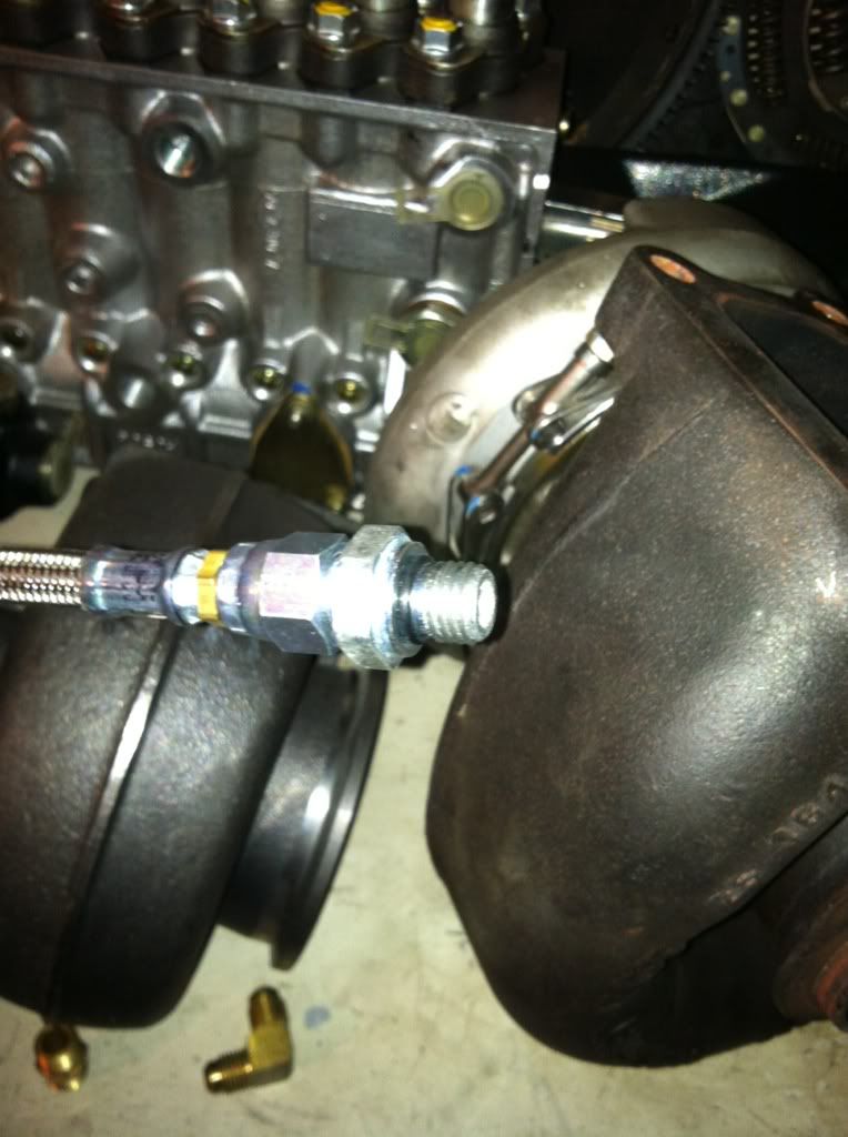
also the oil feed line is a odd one...required a m12x1.5 straight thread metric o-ring fitting on it
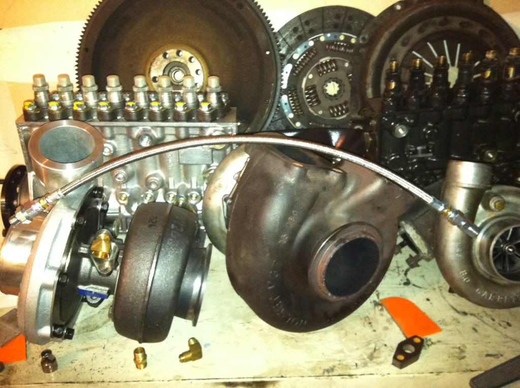
got the e-pump mounted and some of the exhaust welded up...needing some 2.5" v bands before i complete the exhaust
#68
10-01-2012, 11:05 PM
Postmaster
#69
10-02-2012, 11:08 AM
#70
10-02-2012, 08:22 PM
Join Date: Nov 2008
Location: Buckley, WA
Posts: 2,851
Likes: 0
Received 0 Likes
on
0 Posts
#71
10-03-2012, 05:40 PM
Join Date: Nov 2008
Location: Buckley, WA
Posts: 2,851
Likes: 0
Received 0 Likes
on
0 Posts
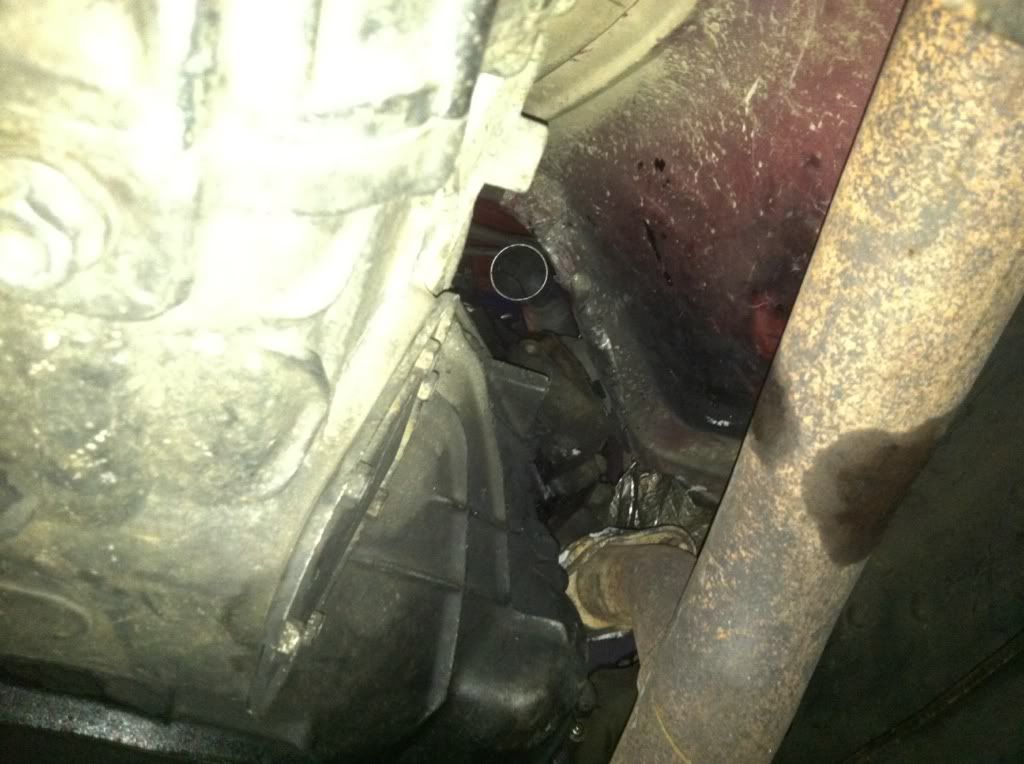
ended up not being so simple LOL
 here is how it had to bend and go all sorts of weird angles
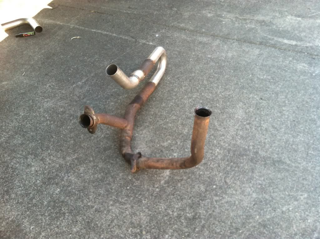
waiting on 2.5" vbands to weld on to make it a 2peice set up...then ill wire wheel it, high temp paint, then wrap it all
here it is

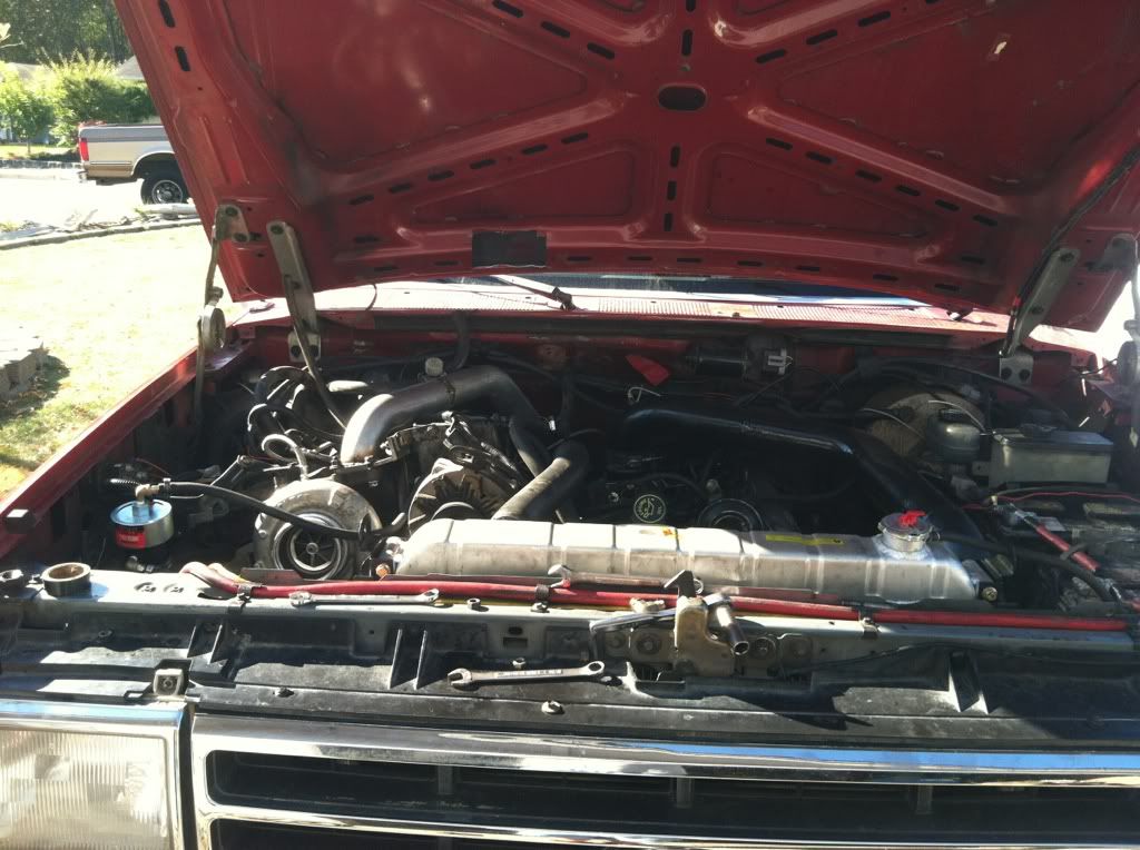
i got the oil feed/ drain hooked up (drain into the lift pump location is a little tricky with the vbelt set up...hope it works) , fuel pump hooked up, just need to make then intake tubes, hook up heater hoses and vacuum hoses and CDR....should be running tomorrow night

#72
10-03-2012, 06:01 PM
Postmaster
#73
10-03-2012, 06:11 PM
Join Date: Nov 2008
Location: Buckley, WA
Posts: 2,851
Likes: 0
Received 0 Likes
on
0 Posts
#74
10-04-2012, 10:21 AM
#75
10-04-2012, 10:21 AM