When you click on links to various merchants on this site and make a purchase, this can result in this site earning a commission. Affiliate programs and affiliations include, but are not limited to, the eBay Partner Network.
they are all on the back row of the 3rd pic....white/green on left, black in middle and tan/violet on left....the flash washed out the tan coloring....
they were all on the back row of the connector as shown in the photo.
when you say back row, its the bottom row?
Also, if you were to count pin numbers 1-11, 1 being on left what would they be?
The white.green is to the left of the black. I dont see the tan/violet, is it hidden behind the front row?
Also, if you were to count pin numbers 1-11, 1 being on left what would they be?
The white.green is to the left of the black. I dont see the tan/violet, is it hidden behind the front row?
thanks!
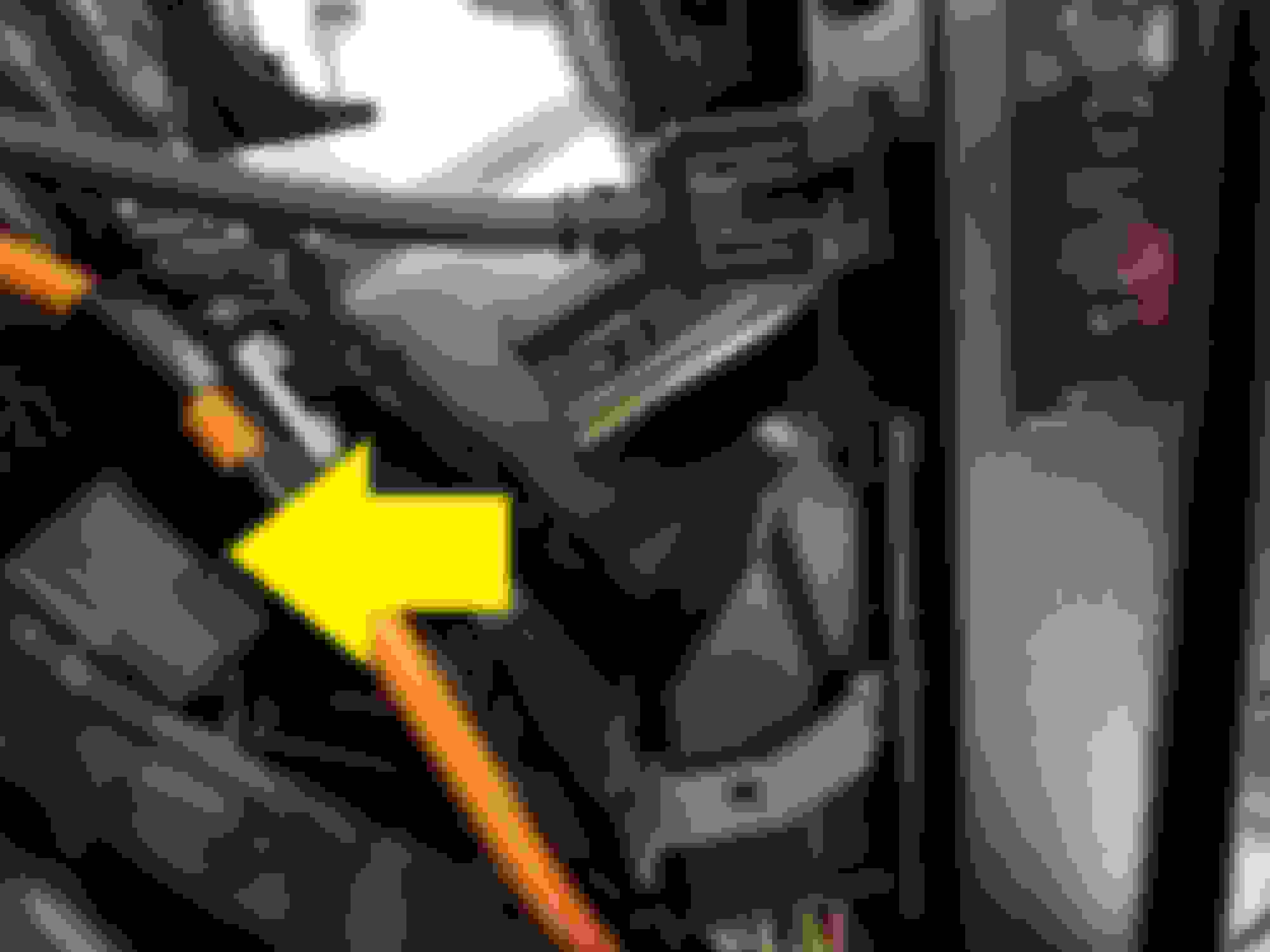
The front row has the 4 open pin slots.....the left open pin slot you will see the white/green on the "back" pin row...then the 2nd from left open pin slot you will see the black wire on the "back" row...then the 3rd from the left open pin slot you will find the tan/violet wire on the back row......
not shown clearing is the other half of the plug....the corresponding slots on the top half are open....that is were you would inset pins to make a connection provided you have the correct style pins to crimp onto your wires to fit the plug.
Let me get this right, you are going from a factory Super Duty camera to an aftermarket radio right?? If so, I have done this 3 times and it has worked like a charm. This is what I have for the Tech info:
Ok for the tech data. The camera connector beneath the tail gate is C497 and is a 6 conductor cable.
Pin 1 is Violet with Gray strip and is +12 volts
Pin 2 is White with Green strip and is Video +
Pin 3 is Brown with Violet strip and is Video -
Pin 4 is Black and is a ground shield for Video. This is Not power ground and should not be used for Power Ground.
Pin 5 is Black on Male connector and Black with White stripe on Female connector and is Power Ground.
Pin 6 is not used.
Hope this helps
hummmm, I'm trying to do this on my truck (05 F350) and so far I have everything hooked up the same as you described and all I get is a black screen on my a/m head unit along with the disclaimer saying the image may be reversed.
What I have done
Pioneer dvd/nav/radio head unit - RCA to Rear Video Input
pin 1 - Tan/Brown - 12v+
pin 2 - white/green - RCA+
pin 3 - Brown/blue (I think) - RCA-
pin 4 - Black - Not used
pin 5 - Black/White - 12v-
pin 6 - non-existent
is there something i'm missing? would it hurt the camera to switch the RCA +&- to test it as long as i don't put it to the 12v? would it hurt to ground both the black and black/white together?
I just recently purchased a 2016 F250 XL, which did not have the rear camera, and I added one. (Actually, i added a new head unit (Kenwood), front camera, rear camera, dash camera, remote start, and a switched accessorie (cig lighter) 4 power port.
When it came to the rear camera, i studied everything i could find, compiled what i thought to be true. then went to work.
***WARNING BEFORE YOU READ TOO FAR THIS ENDED UP NOT WORKING, MAYBE SOMEONE ELSE CAN GET IT****
I decided i could use the existing main harness wiring for the camera, instead of running the vid wire the length of the truck. Here is what i found.
Under the truck I found this:
This connector had many wires coming in, but not all coming out, upon closer inspection some of those were the camera wires, as per the wire diagrams and forum entries i had read. So I tapped in. In ended up with this.
Great! Now on to the front!
Up under the dash behind the glove box, hidden behind the Sync module, i found this:
Corrrect wires colors, unused, it fit the description. So, I tapped in...and....NOTHING.
Back to trouble shooting. Found out the power in the harness in the rear worked just find, as did the ground. But those VID+ and VID - did not make it up front.
I gave up here, and just ran the video wire from the camera to the head unit. Works great now. (If i had the HARNESS diagrams (Not the wiring diagram) i probably would have figured it out, but it was late, the wife was calling with an increasingly agitated tone.)
Let me get this right, you are going from a factory Super Duty camera to an aftermarket radio right?? If so, I have done this 3 times and it has worked like a charm. This is what I have for the Tech info:
Ok for the tech data. The camera connector beneath the tail gate is C497 and is a 6 conductor cable.
Pin 1 is Violet with Gray strip and is +12 volts
Pin 2 is White with Green strip and is Video +
Pin 3 is Brown with Violet strip and is Video -
Pin 4 is Black and is a ground shield for Video. This is Not power ground and should not be used for Power Ground.
Pin 5 is Black on Male connector and Black with White stripe on Female connector and is Power Ground.
Pin 6 is not used.
Hope this helps
I dont do too much electric work mostly audio but video no clue so can you explain how to turn the video + and - and the ground shield into a yellow rca
Let me get this right, you are going from a factory Super Duty camera to an aftermarket radio right?? If so, I have done this 3 times and it has worked like a charm. This is what I have for the Tech info:
Ok for the tech data. The camera connector beneath the tail gate is C497 and is a 6 conductor cable.
Pin 1 is Violet with Gray strip and is +12 volts
Pin 2 is White with Green strip and is Video +
Pin 3 is Brown with Violet strip and is Video -
Pin 4 is Black and is a ground shield for Video. This is Not power ground and should not be used for Power Ground.
Pin 5 is Black on Male connector and Black with White stripe on Female connector and is Power Ground.
Pin 6 is not used.
Hope this helps
what harness did you use to connect to the factory tailgate? All the ones I see are rcas for like a aftermarket camera
This Hennessey Takes the Expedition Tremor's Off-Roading Capability to the Next Level
Slideshow: The VelociRaptor Expedition gains a lift, upgraded suspension, Brembo brakes, and trail-ready equipment while retaining the stock 440-horsepower EcoBoost V6.
Rezvani's Latest Post-Apocalyptic Monster Is a Ford F-150 Raptor Underneath
Slideshow: Called the Fortress, the 850-horsepower pickup combines Raptor underpinnings with military-inspired features, survival equipment, and a starting price of $285,000.