


Floating gages
Thread Starter
|
Posting Guru
Joined: Jul 2010
Posts: 1,154
Likes: 2
From: Marysville, WA
Floating gages
For everyone here that has gages (temp/gas/oil) that seem to wander or float, I am going to attempt to replace the factory IVR (Instrument Voltage Regulator) with aftermarket parts from Radio Shack, and make it fit in the factory IVR case. I want to do this so it will still snap on to the factory gage cluster printed circuit board.
As seen below, the factory IVR is not very robust, but is reliable. It does it's job very simply and this allows for the output to vary, ie: "float". This is due to no temperature compensation, and variable voltage input.
Here is the IVR unbolted from the back of the instrument cluster:

I have already spread the edges open in preparation to open it. The 12v input is on the right and the 5v output is on the left. The small screw above the 5v output is for voltage adjustment. At center just below the mounting tab is the copper ground conductor. Turning the screw out reduces voltage and vice-versa.
Here is the inside:

This "regulator" works by heating the upper arm to move away from the lower contact. 12v is applied to the lower arm, through the contact to the upper arm. As the upper arm heats up from the resistance to ground, it will move away from the lower contact. It will do this rapidly. The voltage output is dependent upon how long the contacts are closed. Our gages are slow to react, so these transient voltage spikes do not rapidly affect gage position. I have looked at my factory manuals and have not found an exact voltage that these are supposed to operate at, but the general consensus I have found is around 5v.
My plan is to use a 7805 5V fixed voltage regulator and two 10uf capacitors. The 7805 is good for 1 amp, which is plenty of power for gages. The capacitors remove voltage spikes. There are other variations of this basic schematic, usually with more capacitors and diodes, but overkill, IMO. My regulator will not be adjustable, but I do not think it needs to be. We shall see.
Schematic:
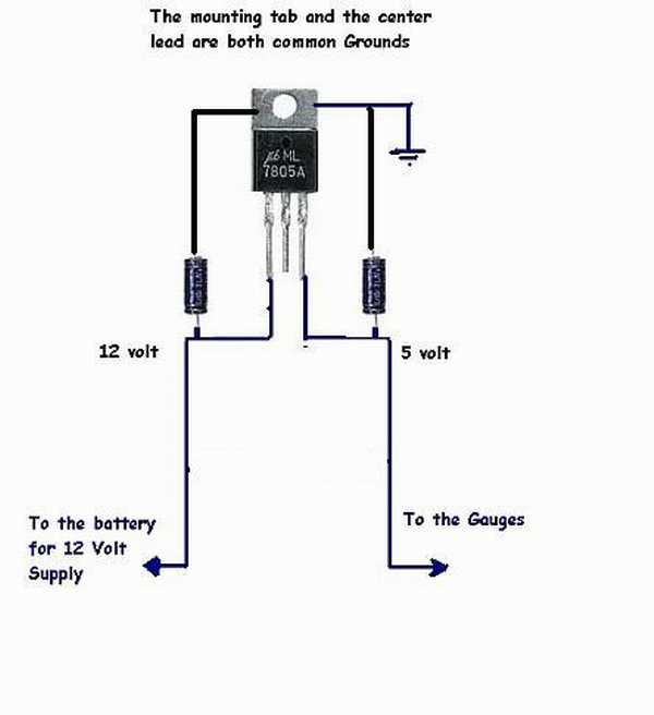
Schematic is from this site. And while his was installed in a 1966 Mustang, it should apply to ours also.
Please do not respond to this post yet. I should have it up and running tomorrow.

As seen below, the factory IVR is not very robust, but is reliable. It does it's job very simply and this allows for the output to vary, ie: "float". This is due to no temperature compensation, and variable voltage input.
Here is the IVR unbolted from the back of the instrument cluster:
I have already spread the edges open in preparation to open it. The 12v input is on the right and the 5v output is on the left. The small screw above the 5v output is for voltage adjustment. At center just below the mounting tab is the copper ground conductor. Turning the screw out reduces voltage and vice-versa.
Here is the inside:
This "regulator" works by heating the upper arm to move away from the lower contact. 12v is applied to the lower arm, through the contact to the upper arm. As the upper arm heats up from the resistance to ground, it will move away from the lower contact. It will do this rapidly. The voltage output is dependent upon how long the contacts are closed. Our gages are slow to react, so these transient voltage spikes do not rapidly affect gage position. I have looked at my factory manuals and have not found an exact voltage that these are supposed to operate at, but the general consensus I have found is around 5v.
My plan is to use a 7805 5V fixed voltage regulator and two 10uf capacitors. The 7805 is good for 1 amp, which is plenty of power for gages. The capacitors remove voltage spikes. There are other variations of this basic schematic, usually with more capacitors and diodes, but overkill, IMO. My regulator will not be adjustable, but I do not think it needs to be. We shall see.
Schematic:
Schematic is from this site. And while his was installed in a 1966 Mustang, it should apply to ours also.
Please do not respond to this post yet. I should have it up and running tomorrow.
Posting Guru
Joined: Jan 2012
Posts: 1,410
Likes: 1
From: Dallas, GA
Hey Don...The EVTM states, as you do, the 5VDC is pulsating. Also keep in mind that it should not be 12 volts supplied to the regulator. There is an 8 or 9 ohm resister up stream of the regulator so the supplied voltage would be something less than 12.
Not sure why it would be a "pulsating" voltage to the instruments but it must be done for a reason right? The only thing I can think of is maybe if you supply a constant voltage to the sendors, it might shorten their life from overheating?? Being that the sendors are variable resistors, a constant voltage supply may overheat them?
Not sure why it would be a "pulsating" voltage to the instruments but it must be done for a reason right? The only thing I can think of is maybe if you supply a constant voltage to the sendors, it might shorten their life from overheating?? Being that the sendors are variable resistors, a constant voltage supply may overheat them?
Moderator


Joined: Jan 2001
Posts: 56,999
Likes: 2,746
From: Virginia

It does it's job very simply and this allows for the output to vary, ie: "float". This is due to no temperature compensation, and variable voltage input.

Senior User
Joined: Feb 2012
Posts: 177
Likes: 0
From: Grants Pass, OR
Hey Don...The EVTM states, as you do, the 5VDC is pulsating. Also keep in mind that it should not be 12 volts supplied to the regulator. There is an 8 or 9 ohm resister up stream of the regulator so the supplied voltage would be something less than 12.
Not sure why it would be a "pulsating" voltage to the instruments but it must be done for a reason right? The only thing I can think of is maybe if you supply a constant voltage to the sendors, it might shorten their life from overheating?? Being that the sendors are variable resistors, a constant voltage supply may overheat them?
Not sure why it would be a "pulsating" voltage to the instruments but it must be done for a reason right? The only thing I can think of is maybe if you supply a constant voltage to the sendors, it might shorten their life from overheating?? Being that the sendors are variable resistors, a constant voltage supply may overheat them?
Senior User
Joined: Feb 2012
Posts: 177
Likes: 0
From: Grants Pass, OR
For everyone....
...
...
My plan is to use a 7805 5V fixed voltage regulator and two 10uf capacitors. The 7805 is good for 1 amp, which is plenty of power for gages. The capacitors remove voltage spikes. There are other variations of this basic schematic, usually with more capacitors and diodes, but overkill, IMO. My regulator will not be adjustable, but I do not think it needs to be. We shall see.
...
...
...
...
My plan is to use a 7805 5V fixed voltage regulator and two 10uf capacitors. The 7805 is good for 1 amp, which is plenty of power for gages. The capacitors remove voltage spikes. There are other variations of this basic schematic, usually with more capacitors and diodes, but overkill, IMO. My regulator will not be adjustable, but I do not think it needs to be. We shall see.
...
...
Thread Starter
|
Posting Guru
Joined: Jul 2010
Posts: 1,154
Likes: 2
From: Marysville, WA
#1. The 12v supplied is nominal. With my 3G alt, I get a steady 14.2v with the engine running. The 7805 datasheet from National Semiconductor states 7.5v to 35v input for 5v output. Even with the inline resistor, voltage will be above the 7.5v minimum. Also, the higher the input voltage, the more that the current is transferred to heat.
#2. Our gages are slow to react. As such pulsating voltage is acceptable.
Dave, tell my why then, with a warmed up engine, that I can turn the key on, but not start the engine, check the readings on the gages, then start the engine, and have different readings with the higher input voltage as the only change? BTW, The IVR with no output load puts out the same as input voltage, thus making output side resistance a key factor. And since the output resistance(gages/wiring/senders) is variable, the subsequent voltage provided will not be constant.
#3. The IVR case will act as the heat sink.
Posting Guru
Joined: Jan 2012
Posts: 1,410
Likes: 1
From: Dallas, GA
I would think, not sure though, that if downstream load changes (i.e. you loose a temp gage for some reason) that will change the current draw which will then change rate at which the bi-metalic strip heats up....and therefore the rate at which it cycles and that would affect the average voltage.
This may be the way it changes it's output depending on load. Just thinking theoretically though. I don't know for sure how it functions.
This may be the way it changes it's output depending on load. Just thinking theoretically though. I don't know for sure how it functions.
Trending Topics
FTE Legend


Joined: Jul 2010
Posts: 32,875
Likes: 48
From: Northeast, OK
Subscribed. And, btw, I have several IVR's that I could measure if need be. And, I could put the 'scope on them to get pulse-width and voltage - but only if needed as I seem to have other things to do with my engine.
FTE Stories
Ford Trucks for Ford Truck Enthusiasts

Top 10 Fords at 2026 Carlisle Ford Nationals
Joe Kucinski
3 Best / 3 Worst Parts of Modern Ford Ownership
Brett Foote
10 Amazing Upgrades That Solve Common Ford Truck Owner Headaches
Pouria Savadkouei
Every 2026 Ford Engine Explained
Brett Foote
10 Ugly Ford Trucks That We Still Kinda Love
Joe Kucinski
10 Things Every Truck Owner NEEDS (2026 Edition)
Michael S. Palmer
Rezvani's Latest Post-Apocalyptic Monster Is a Ford F-150 Raptor Underneath
Verdad Gallardo
Top 10 Most Expensive Ford Trucks Ever Sold on Bring a Trailer
Joe Kucinski
2027 Ford Super Duty Buyer's Guide (Every Model, Engine, & Package)
Brett FooteModerator
Joined: Jan 2001
Posts: 56,999
Likes: 2,746
From: Virginia
Well, we are getting into deeper than what I know, so maybe we can all learn together, I am putting my faith in the Ford engineers hoping they had their thinking caps on, but we all know they are human just like us so;
I looked at the picture above again, and correct me if I am wrong, but doesn't the coil of wire(the heating element) wind around and have it's own ground? If the other end is hooked to the input, that would mean the heating coil and the amount of heat it generates would not be affected by the gauge load.
And to explain further, yes you will get 12v with no load, I do not know if the lower voltage is a function of the inline resistor mentioned, or just because our meters are not fast enough.
But it's all about duty cycle. The 12v will be there more or less depending on the input voltage. It's just like a light dimmer in your house with the old type incandescent bulbs. The dimmer "chops" or "slices" the 120v up into pieces. The bulb still gets the 120v when it's dimmed, but it only gets a little "sliver" of the 120v, so the filament only glows dim. The guages in our old trucks also run on heating elements in the gauges themselves, so they will work off a "piece" of the 12v input. The needle is actually hooked to a bi-metal lever in the gauge itself.
Thread Starter
|
Posting Guru
Joined: Jul 2010
Posts: 1,154
Likes: 2
From: Marysville, WA
Gary, I put a 50 ohm load on the IVR and the opening/closing rate was very slow, maybe 2 or 3 times a second. With a 100 ohm load, 5 times per second. I do not have a pulse counter, just estimating.
Voltages jumped from 1v to 7.5v during the sweeps with many times showing zero volts.
I now see the factory IVR as old news. I am sure they debated the design 40 years ago. Solid state semiconductors have changed the playing field.
Here is the assembled new IVR before testing. I bent the tab on the 7805 because it will be against the curved side of the IVR case. I will be coating the solder joints with liquid tape.

And here is the first test. Blue Point meter on left is battery supply voltage(Optima Yellow Top), Fluke is output, and the new IVR on the right. This shot is with a 60 ohm load. A 200 ohm load had the same output and the 7805 barely got warm.

Instead of non-polarized capacitors, I used polarized 10uf 35v caps so that they would fit in the IVR case. I also put a couple bends in the IVR mounting tab so it would sit a bit above the printed circuit board instead of on it.
And here it is going back together.

One more test after closing the case and shows 4.95v with 100 ohm load. Heading out to put it in the truck.
Voltages jumped from 1v to 7.5v during the sweeps with many times showing zero volts.
I now see the factory IVR as old news. I am sure they debated the design 40 years ago. Solid state semiconductors have changed the playing field.
Here is the assembled new IVR before testing. I bent the tab on the 7805 because it will be against the curved side of the IVR case. I will be coating the solder joints with liquid tape.
And here is the first test. Blue Point meter on left is battery supply voltage(Optima Yellow Top), Fluke is output, and the new IVR on the right. This shot is with a 60 ohm load. A 200 ohm load had the same output and the 7805 barely got warm.
Instead of non-polarized capacitors, I used polarized 10uf 35v caps so that they would fit in the IVR case. I also put a couple bends in the IVR mounting tab so it would sit a bit above the printed circuit board instead of on it.
And here it is going back together.
One more test after closing the case and shows 4.95v with 100 ohm load. Heading out to put it in the truck.
FTE Legend
Joined: Jul 2010
Posts: 32,875
Likes: 48
From: Northeast, OK
Just checked the gauges laying on the bench. All three show 12.5 ohms across the guage, and it doesn't change with reversed polarity, so I don't think the rest of the instrument panel nor the IVR is impacting those readings. Given that, any resistance of the sending unit, such as the 10 ohms full scale on the gas, would be added to the 12.5. IOW, we are looking at a minimum resistance of 22.5 ohms @ 5 volts = .22 amp.
I think I'll see if I can find the values of the other sending units.
I think I'll see if I can find the values of the other sending units.
FTE Legend
Joined: Jul 2010
Posts: 32,875
Likes: 48
From: Northeast, OK
These are readings from the senders on my 351M, but should be good for others as the gauges are common. Looks like the max we would see would be about 1/2 amp.
Also, while it isn't clear the calculation was done by adding the 12.5 ohms of the gauge to that of the sender.
Also, while it isn't clear the calculation was done by adding the 12.5 ohms of the gauge to that of the sender.
Senior User
Joined: Feb 2012
Posts: 177
Likes: 0
From: Grants Pass, OR
Well, we are getting into deeper than what I know, so maybe we can all learn together, I am putting my faith in the Ford engineers hoping they had their thinking caps on, but we all know they are human just like us so;
I looked at the picture above again, and correct me if I am wrong, but doesn't the coil of wire(the heating element) wind around and have it's own ground? If the other end is hooked to the input, that would mean the heating coil and the amount of heat it generates would not be affected by the gauge load.
And to explain further, yes you will get 12v with no load, I do not know if the lower voltage is a function of the inline resistor mentioned, or just because our meters are not fast enough.
But it's all about duty cycle. The 12v will be there more or less depending on the input voltage. It's just like a light dimmer in your house with the old type incandescent bulbs. The dimmer "chops" or "slices" the 120v up into pieces. The bulb still gets the 120v when it's dimmed, but it only gets a little "sliver" of the 120v, so the filament only glows dim. The guages in our old trucks also run on heating elements in the gauges themselves, so they will work off a "piece" of the 12v input. The needle is actually hooked to a bi-metal lever in the gauge itself.
I looked at the picture above again, and correct me if I am wrong, but doesn't the coil of wire(the heating element) wind around and have it's own ground? If the other end is hooked to the input, that would mean the heating coil and the amount of heat it generates would not be affected by the gauge load.
And to explain further, yes you will get 12v with no load, I do not know if the lower voltage is a function of the inline resistor mentioned, or just because our meters are not fast enough.
But it's all about duty cycle. The 12v will be there more or less depending on the input voltage. It's just like a light dimmer in your house with the old type incandescent bulbs. The dimmer "chops" or "slices" the 120v up into pieces. The bulb still gets the 120v when it's dimmed, but it only gets a little "sliver" of the 120v, so the filament only glows dim. The guages in our old trucks also run on heating elements in the gauges themselves, so they will work off a "piece" of the 12v input. The needle is actually hooked to a bi-metal lever in the gauge itself.
http://i608.photobucket.com/albums/t...0/duelfuel.jpg
.

Post Fiend
Joined: Jul 2004
Posts: 8,786
Likes: 28
From: Northern California
#1. The 12v supplied is nominal. With my 3G alt, I get a steady 14.2v with the engine running. The 7805 datasheet from National Semiconductor states 7.5v to 35v input for 5v output. Even with the inline resistor, voltage will be above the 7.5v minimum. Also, the higher the input voltage, the more that the current is transferred to heat.
#2. Our gages are slow to react. As such pulsating voltage is acceptable.
Dave, tell my why then, with a warmed up engine, that I can turn the key on, but not start the engine, check the readings on the gages, then start the engine, and have different readings with the higher input voltage as the only change?
The purpose of the IVR is not really to reduce the voltage as much as to keep it at a relatively constant level so the gauges don't fluctuate wildly. The resistor is what reduces the voltage to within the tolerance level, and the IVR keeps it stable as fluctuations demand. You can adjust the output, higher or lower, depending on your needs with the adjustment screw.
The IVR pulses so the gauges are not as sensitive to fast fluctuation from the charging system.
The gauges are supplied with a constant regulated voltage from the IVR. The wire from the sending unit to the specific gauges is the "Ground" wire. The variable resistor in the sending units between ground and the gauge is what makes the needle move, not the IVR. This is why you only have one IVR to feed three gauges. Each gauge has the same amount of voltage going to them from the IVR.
FTE Legend
Joined: Jul 2010
Posts: 32,875
Likes: 48
From: Northeast, OK
I guess while it is sometimes nice to know how the old system worked, I'm with Don - the IVR is old news. The real question is how does 4.95 volts run the gauges, meaning is it high enough to give accurate readings, and will the 7805 provide adequate current w/o overheating.
But, speaking of Don, did he get lost between his house and his truck? He said he was going out to try it about 6 hours ago.
But, speaking of Don, did he get lost between his house and his truck? He said he was going out to try it about 6 hours ago.