1954 f100
#31
 03-13-2012, 09:10 PM

I gave you the wrong directions on how to find the rear axle info.
It's in the WHITE band "articles/specs" tab. But here's a direct link:
1948 through 1960 Ford F-1 and F-100 Rear Axle (differential) Swaps .: Articles
One interesting note it contains: "63-77 Lincoln, LTD, and Thunderbirds had 9 3/8 inch centers, housings were cut away at the gasket surface for ring gear clearance, one curved rib at the front top portion of differential, strong but poor selection of axle ratios."
Another good reason to go with a different unit, the Lincoln is not a true 9", 9" R&P do not fit.
#32
03-13-2012, 11:29 PM
Join Date: Mar 2012
Posts: 332
Likes: 0
Received 0 Likes
on
0 Posts
Regarding the rear end.
Looking at the tag it says WGB-AB which makes it
<table id="table2" border="1" cellpadding="2" cellspacing="0" width="98%"><tbody><tr><td>Lincoln Mark Series late 78-79</td> <td align="center"> 2.47</td> <td align="center"> 9.0</td> <td align="center"> NL</td> <td align="center"> 28</td> <td align="center"> from 5/1/78, Mark V</td></tr></tbody></table>
Ford Rear Axle Assembly Identification - Page 09 - FORDification.com
#33
03-18-2012, 10:16 PM
Join Date: Mar 2012
Posts: 332
Likes: 0
Received 0 Likes
on
0 Posts
Update,
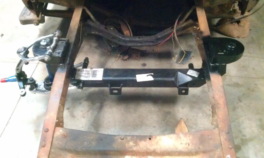
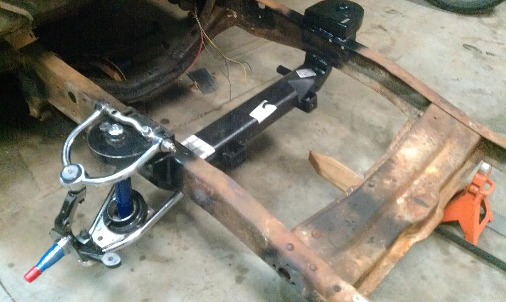
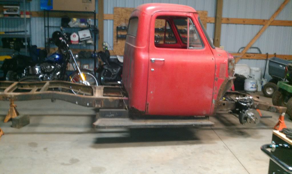
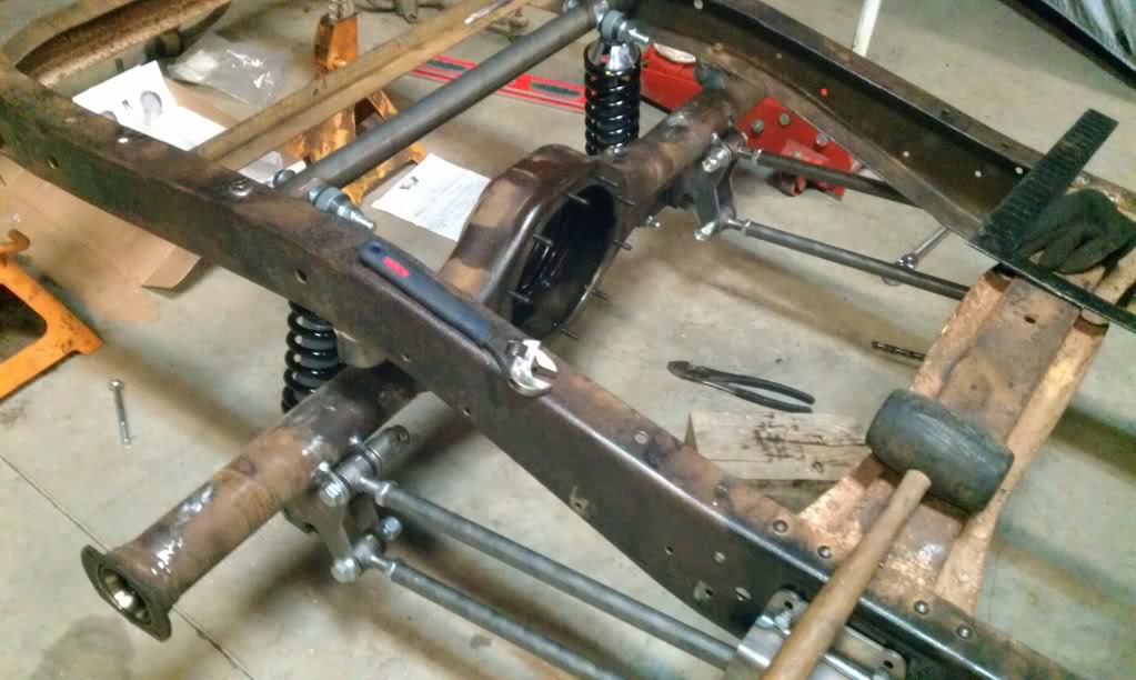
My front suspension arrived a lot earlier than expected. So installation began yesterday. Installation wasn't too bad. One thing that bothered me though was the bolts for the upper control arms. Were fine threaded and the nuts were very small, only 4 rows of threads. I cant imagine how well they would hold up to any kind of abuse. I will likely replace them with Grade 8 bolts and larger nuts and lock washers.
The photos are just a mock up nothing bolted was tightened.
#34
03-18-2012, 11:05 PM
Fine thread bolts are actually better. More contact thread per inch. As for the nuts, yeah it'd probably be better to have more contact with a thicker nut but there could be a reason for them being thinner too. Keep in mind that most the stress and load is all on the lower arms. Essentially the uppers are just there to locate the top of the spindles. The only real serious stress the uppers will see are when cornering. If you can get thicker nuts to work, I'd probably do that. The last thing you want is for the upper arm to slip within the adjustment slots and ruin your front end alignment or worse, cause an accident.
Otherwise, looks pretty good though! You going to add boxing plates?
Otherwise, looks pretty good though!
You going to add boxing plates?
#35
03-18-2012, 11:14 PM
Join Date: Mar 2012
Posts: 332
Likes: 0
Received 0 Likes
on
0 Posts
I didn't know that about fine threaded bolts, makes sense though. Yeah I am going to cut out the cross member sitting further back in the picture. Then proceed to cleaning the inside of the frame rails like I did the outside for welding the hats and gussets. Then I will box in the frame rails with 3/16 steel plating. 
#36
03-19-2012, 12:42 AM
Sure those thin nuts aren't locking nuts? Locking nuts are used in conjunction with standard nuts used in an adjustment application to keep the primary nuts from loosening. The standard nuts are tightened first then the locking nut is tightened against it using a second wrench. It could also be a clearance issue.
Unless you are getting it for free, 1/8" plate is plenty thick enough for boxing plates (even that is thicker than the frame, thicker material requires more heat with the resulting heat warpage without any significant strength gain.). I like to cut my boxing plates so they fit inside the rails, then inset them ~1/8" (easy to do with a couple scraps of the 1/8" plate and welding magnets wider than the frame, put the scrap spacers between the magnet and the boxing plate then span the frame flanges with the magnet. That gives you a fillet weld that is easy to do and clean looking rather than trying to do a 90* upside down butt weld that is near impossible to weld and/or grind clean. It is also not necessary to weld the boxing plates in solid, a skip weld of 1-1/2" beads 6" apart is plenty strong and much less likely to warp the frame. Be sure to leave large enough access holes in the plates to reach any bolts or drill for installing crush tubes for thru bolts.
Unless you are getting it for free, 1/8" plate is plenty thick enough for boxing plates (even that is thicker than the frame, thicker material requires more heat with the resulting heat warpage without any significant strength gain.). I like to cut my boxing plates so they fit inside the rails, then inset them ~1/8" (easy to do with a couple scraps of the 1/8" plate and welding magnets wider than the frame, put the scrap spacers between the magnet and the boxing plate then span the frame flanges with the magnet. That gives you a fillet weld that is easy to do and clean looking rather than trying to do a 90* upside down butt weld that is near impossible to weld and/or grind clean. It is also not necessary to weld the boxing plates in solid, a skip weld of 1-1/2" beads 6" apart is plenty strong and much less likely to warp the frame. Be sure to leave large enough access holes in the plates to reach any bolts or drill for installing crush tubes for thru bolts.
#37
03-19-2012, 10:48 PM
Join Date: Mar 2012
Posts: 332
Likes: 0
Received 0 Likes
on
0 Posts
#39
04-18-2012, 09:14 PM
Join Date: Mar 2012
Posts: 332
Likes: 0
Received 0 Likes
on
0 Posts
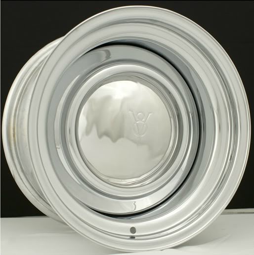
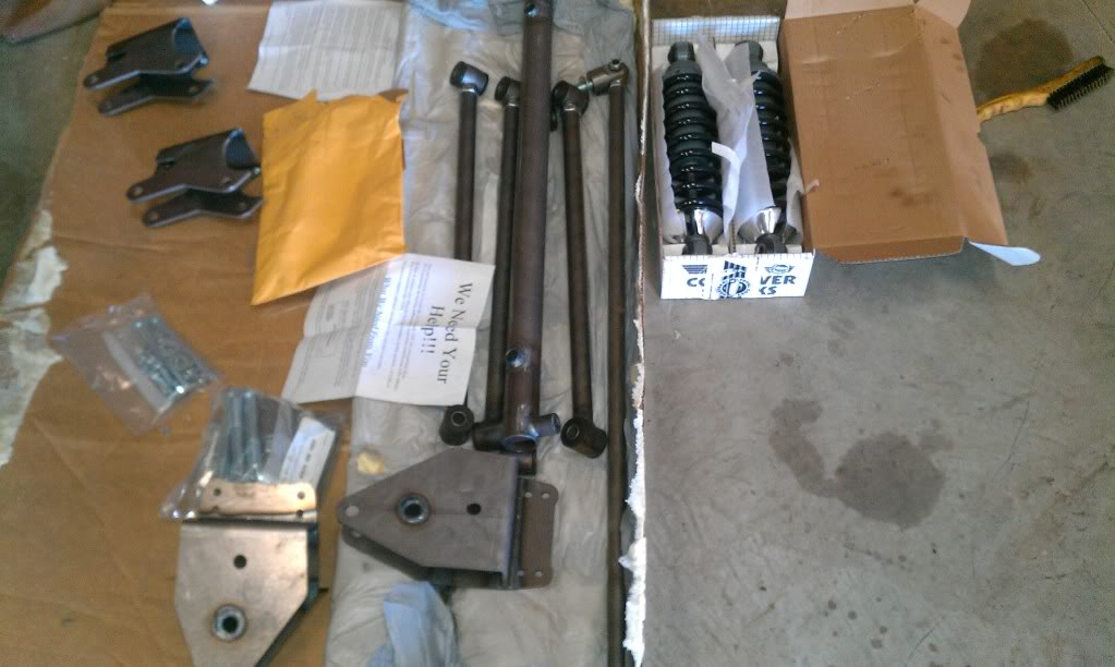
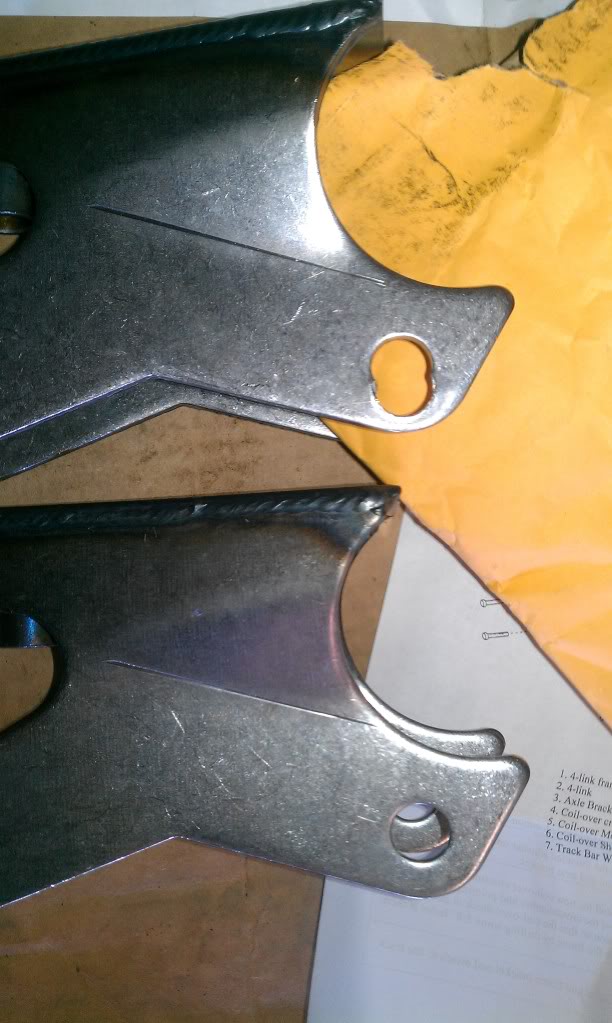
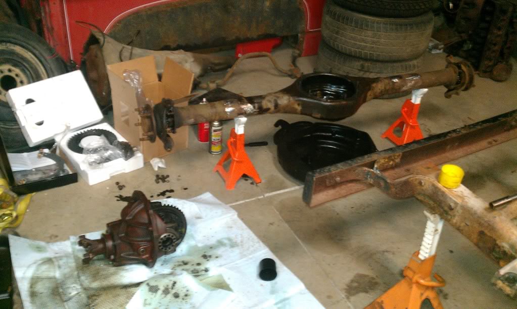
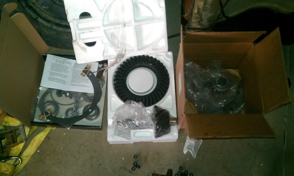
Welp, not much been going on lately, I am about to rebuild the 9 inch. I ordered my wheels the backspacing which will set the wheel base at factory. My rear suspension came in today from mid fifty - TCI. TCI messed up a bolt location on an axle mount. I sure hope they can resolve the issue. Photos attached.
#41
04-18-2012, 10:43 PM
Join Date: Mar 2012
Posts: 332
Likes: 0
Received 0 Likes
on
0 Posts


#43
04-29-2012, 10:07 PM
Join Date: Mar 2012
Posts: 332
Likes: 0
Received 0 Likes
on
0 Posts
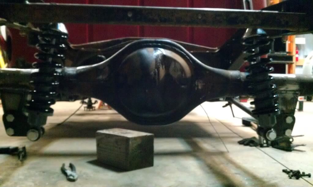
TCI replaced the bracket without issue and very fast. It came in on Monday. The rear suspension is 90% done. It came with a diagonal track bar which I may opt out for a regular panhard bar.
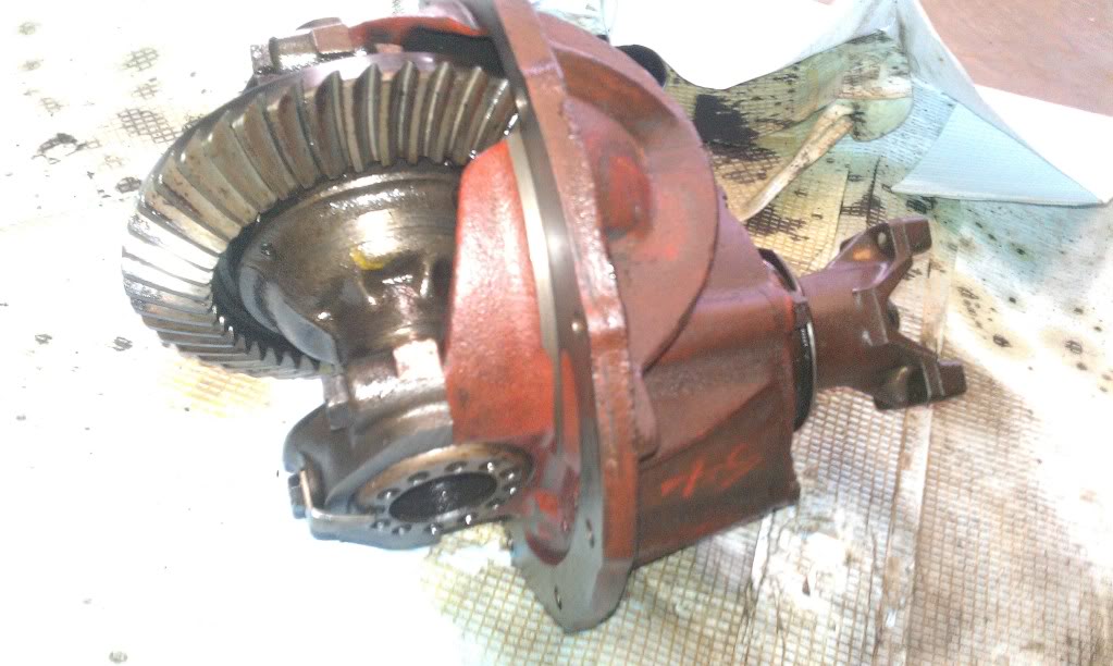
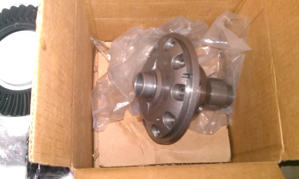
The carrier has clearance issues with the housing. Right where the pinion gear bearing sits in the housing, it rubs. I ran out of time this weekend to get the rear end put together.
The carrier has clearance issues with the housing. Right where the pinion gear bearing sits in the housing, it rubs. I ran out of time this weekend to get the rear end put together.
#44
04-30-2012, 09:21 AM
#45
04-30-2012, 05:34 PM
Join Date: Mar 2012
Posts: 332
Likes: 0
Received 0 Likes
on
0 Posts
Yeah, I haven't put any boxing plates in yet. Currently the Crossmember is bolted in with grade 8 bolts through the top and bottom of the frame rail. It is also welded to the bottom of the frame rail. The plan is to box in the entire section grinding a hole in the plates so that they meet near flush with the crossmember and then weld the boxing plates to the cross member.
When its done, its not coming out. ever...
When its done, its not coming out.
ever...