


Ignition Problem?

Thread Starter
|
Freshman User
Joined: Oct 2011
Posts: 41
Likes: 0
I actually replaced both because the tumbler was worn out and you could start it with a screw driver but yes I did replace the electrical part of the switch.
Thread Starter
|
Freshman User
Joined: Oct 2011
Posts: 41
Likes: 0
Thanks for the helpful diagram fasthauler. I was sure I put that jumper on correctly but I will try again. I figure it's common sense but just to be clear it's one to the + side of the battery and one to the + side of the coil right?
MSEE
Joined: Apr 2004
Posts: 10,386
Likes: 35
From: Austin, TX

Basically you're just making sure that the voltage drops down to the expected level with the key in RUN. With the key in RUN, the coil is connected to the power source through a ballast resistor (resistor wire in the dash harness). When the circuit is complete, the voltage seen at the coil positive terminal is lower than it would be if you connected the coil straight to the power source.
When you checked the voltage at the coil with the key in RUN and saw 12 volts, the points would have been OPEN. This is because no current flows through the coil and hence the ballast, so there is no drop across the ballast. If you were to CLOSE the points, current flows through the circuit, and there is a voltage drop across the ballast resistor. What's left shows up at the coil. This principle is called voltage division.
You just want to check that the voltage goes down to the correct level with the points CLOSED. You can close the points by physically pushing them shut like the distributor shaft does as it rotates. Or you can physically short them across with a screwdriver. The points are just a switch. I mentioned to be careful when you OPEN the circuit afterwards because the coil will have been energized.
GFW had another great idea to temporarily jump power straight to the coil just to make sure the engine runs, because if it doesn't, then that will steer where to go next. Check what you did against fasthauler's diagram to make sure you set it up correctly.
That's an interesting idea. I can't think off the top of my head how that would happen, but it's something to think about. Maybe to be safe, make sure the ground wire in the distributor (that connects the stationary base plate to the moveable breaker plate) is intact.
Cranky Old Guy
Joined: Mar 2008
Posts: 3,562
Likes: 6
From: Raphine, Virginia
Going along with fmc400's suggestion to check ground in the distributor. Make sure the ground strap from engine to firewall is in place. I have had funny things happen I couldn't explain due to that being missing. Curious to see where this problem is. Last time I had this problem with points, it wound up being point gap was too wide, messing with the dwell. Almost drove me nuts.
Fleet Mechanic

Joined: Mar 2004
Posts: 1,398
Likes: 17
From: Hesperia, CA
That is correct as long as somebody didn't put the coil on backwards and that is something that you should check. Make sure the negative side of the coil does go to the distributor. (This shouldn't be a problem unless someone put an aftermarket coil on) The guys on here are giving you some good advice. It shows they have had some experience dealing with these types of problems. Also the point gap is very important. Don't overlook it. The best way to set them is with a dwell meter. If you don't have access to one you can use a feeler gauge. Don't use a dime. (That was for Model A's) I believe the proper gap for that engine was 0.017. You can possibly do a search on FTE and find out for sure.
Thread Starter
|
Freshman User
Joined: Oct 2011
Posts: 41
Likes: 0
Okay so, I have some new info to bring to the table. Just remember I'm learning and I really don't know that much about ignition systems and I haven't had this truck for a long time so please don't crucify me for my dumb assness. I got to looking for the points on my truck to close them manually like fmc suggested and realized it doesn't have any and I also have a little black box mounted over on the driver side fender. This is and electronic ignition setup right!?
A jumper from the battery to the coil still has no effect (don't know if this has anything to do with it being electronic). I cleaned and checked the grounds that I could find (neg post to engine and starter to starter solenoid). I also hooked my multi-meter up (one probe to neg battery post one probe to + side of coil) and I get around 12v with the key on "run" and around 8-9v while the engine is cranking. Could that little black box be the problem? I think that is an ignition control module right?
A jumper from the battery to the coil still has no effect (don't know if this has anything to do with it being electronic). I cleaned and checked the grounds that I could find (neg post to engine and starter to starter solenoid). I also hooked my multi-meter up (one probe to neg battery post one probe to + side of coil) and I get around 12v with the key on "run" and around 8-9v while the engine is cranking. Could that little black box be the problem? I think that is an ignition control module right?
Cranky Old Guy
Joined: Mar 2008
Posts: 3,562
Likes: 6
From: Raphine, Virginia
Well, that'll change things a bit. Stock 74 could be a Duraspark I. Module is aluminum colore unless someone has painted it. How many plugs on it, and what color wires?
FTE Stories
Ford Trucks for Ford Truck Enthusiasts

10 Best Ford Truck Engines We Miss the Most!
Joe Kucinski
2026 Shelby F-150 Off-Road: Better Than a Raptor R?
Brett Foote
2027 Super Duty Carhartt Package First Look: 12 Things You NEED to Know!
Michael S. Palmer
10 Most Surprising 2026 Ford Truck Features!
Joe Kucinski
Top 10 Ford Trucks Coming to Mecum Indy 2026
Brett Foote
5 Best / 5 Worst Ford Truck Wheels of All Time
Joe Kucinski
Ford Super Duty: 5 Things Owners LOVE, 5 Things They LOATHE!
Joe Kucinski
Every 2026 Ford Truck Engine RANKED from WORST to FIRST!
Michael S. Palmer
The Best F-150 Deal of Every Trim Level (XL through Raptor)
Joe Kucinski
Thread Starter
|
Freshman User
Joined: Oct 2011
Posts: 41
Likes: 0
The wires are old and some have paint on them but from what I can tell they are as follows.
On plug has four contacts
wires coming from harness into plug:
green-light blue stripe
orange-light orange strip
light blue
red-whites stripe
and another light blue wire with a little can thing attached to it
from plug to module:
red
white
purple
orange
The other has two contacts but the plug looks like it would accept three.
from harness into plug:
blue
lime green
red-white stripe
from plug to module:
green
black
Fleet Mechanic
Joined: Mar 2004
Posts: 1,398
Likes: 17
From: Hesperia, CA
It certainly sounds like you have a Dura-Spark II system. I dont understand the colors though. On the normal Dura-Spark the plug with the two connections is for the voltage from the ignition switch. One puts twelve volts on the module in the start position. The other one puts twelve volts on the module in the run position. There might not be the twelve volts in the run position and that could definitely be the problem. You need to turn the ignition switch on in the run position and see if there is voltage there. If not then you have found your problem.
MSEE
Joined: Apr 2004
Posts: 10,386
Likes: 35
From: Austin, TX
I figured something was up. Yes, you have electronic ignition.
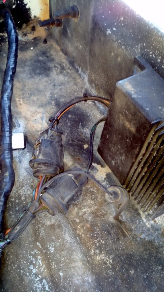
I can't make out from your description what you actually have. Can you post photos of the box and the connectors coming from it?
Most likely you either don't have power to the box in RUN or the box itself is bad. I can't tell from your description where to look for power, especially since you've indicated that things have been moved around, and some wires have paint on them. That's why some good, clear pictures are necessary.
Thread Starter
|
Freshman User
Joined: Oct 2011
Posts: 41
Likes: 0
It certainly sounds like you have a Dura-Spark II system. I dont understand the colors though. On the normal Dura-Spark the plug with the two connections is for the voltage from the ignition switch. One puts twelve volts on the module in the start position. The other one puts twelve volts on the module in the run position. There might not be the twelve volts in the run position and that could definitely be the problem. You need to turn the ignition switch on in the run position and see if there is voltage there. If not then you have found your problem.
Also, it's like I said, those colors may not even be correct. That's just the best I could make out from the years of paint, heat, discoloration, etc of those wires.
Senior User
Joined: Dec 2011
Posts: 142
Likes: 0
From: Round Rock, TX
You need to make sure you have power in the RUN position. You know you have power in the start position, because you state thats the only time the truck will run. Is the starter just grinding away on the flexplate/flywheel while you are testing it? If so, you need to stop, and get this figured out, before you need to pull the transmission and fix more problems. Need to try to take your time and read what these guys are telling you, they are spot on with what is wrong with it. Good luck.
MSEE
Joined: Apr 2004
Posts: 10,386
Likes: 35
From: Austin, TX
Agree with 77393, trying to keep the engine running for 6 to 7 seconds with the starter engaging is going to kill your starter and/or ring gear.
The connector with 4 wires is for the distributor and coil. Two wires are the distributor trigger, one is the coil primary, and the last one is GROUND. Did you say that the harness-side of the second connector has three wires? I only see two in the picture, but maybe it's just the angle.
If the truck-side has three but the module has two on that second connector, then you may have the wrong module. Did the truck ever run in the first place? If they both have two, then next we can check for power.