


Spout connector?

Thread Starter
|
New User
Joined: Jan 2012
Posts: 15
Likes: 0
Spout connector?
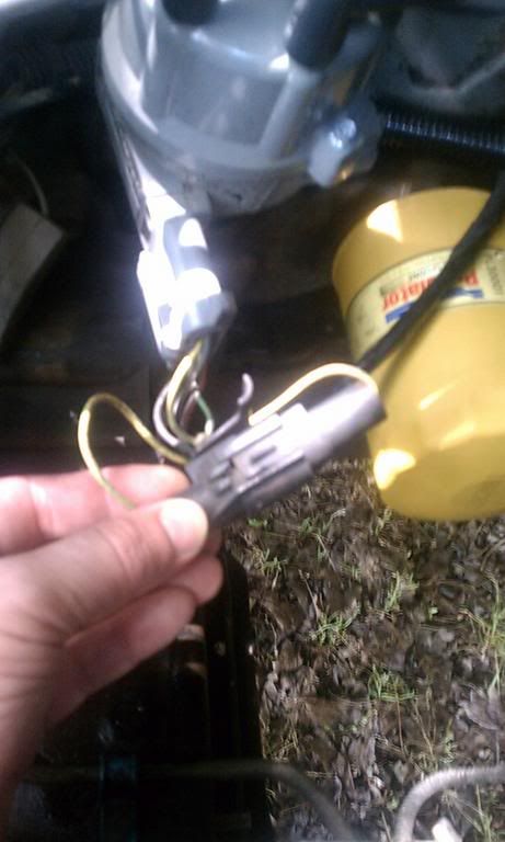
Here is a picture a stole from someone else. This looks identical to mine, except one of the wires is cut on the female end. Where does it suppose to go to? I just bought this truck. This is the spout connector right? 1986 f150 4.9 I6
Last edited by penguintits; Jan 10, 2012 at 09:06 PM. Reason: spelling error
Thread Starter
|
New User
Joined: Jan 2012
Posts: 15
Likes: 0
Thanks! Now the wire on the female end of my spout connector is cut, where is it suppose to go? When I unplug the spout connector the timing should change correct? I'm assuming its not working because of the cut wire.
Also while I'm at it, where is the ISC Idle speed control located on the carburetor? The manual does not show it, only the curb idle speed adjustment and fast idle speed.
Thanks again.
Also while I'm at it, where is the ISC Idle speed control located on the carburetor? The manual does not show it, only the curb idle speed adjustment and fast idle speed.
Thanks again.
Fleet Mechanic

Joined: Jun 2010
Posts: 1,251
Likes: 8
From: North Carolina

Thanks! Now the wire on the female end of my spout connector is cut, where is it suppose to go? When I unplug the spout connector the timing should change correct? I'm assuming its not working because of the cut wire.
Also while I'm at it, where is the ISC Idle speed control located on the carburetor? The manual does not show it, only the curb idle speed adjustment and fast idle speed.
Thanks again.
Also while I'm at it, where is the ISC Idle speed control located on the carburetor? The manual does not show it, only the curb idle speed adjustment and fast idle speed.
Thanks again.
I would also assume that its not working because the wire is cut. Cutting the wire is the same as disconnecting the spout...
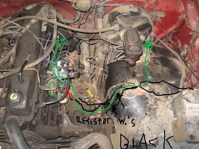
Here is where the ISC speed control motor is:
Thread Starter
|
New User
Joined: Jan 2012
Posts: 15
Likes: 0
Thanks for the info! Your getting me closer to solving this. On the SPOUT connector it is connected to the distributor but the other end has a red crimp going to nothing. I couldnt find a same colored wire near by, instead i found this mess. I found 4 wires connected to each other only by being twisted together. one wire goes to the coil, the other the coil resistor, then one the fire wall the other back end of the motor(either going to the firewall again or to the carburetor area. The other crimp comes from the coil resistor to the area behind the motor/firewall. I need a schematic!
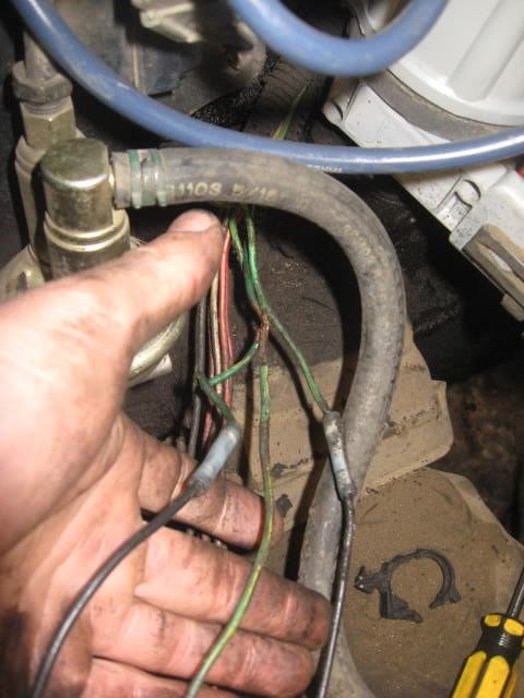
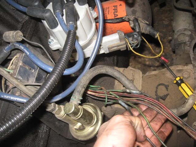
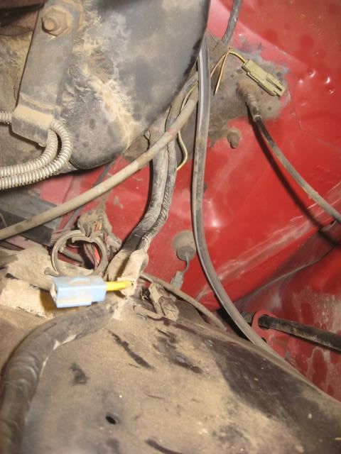
I hope these help...
What is the SPOUT suppose to connect to? the computer right?
The last picture on the driver side fender has two separate connectors that are both yellow same as the SPOUT but i doubt they go to it being so far away.
The truck runs and idles, but dies under a load once I start moving.
Last edited by ctubutis; Jan 12, 2012 at 07:03 PM. Reason: Stacked pictures (easier to see)
Old School Hot Rodder


Joined: Feb 2006
Posts: 6,472
Likes: 11
From: Exmore, VA
Trending Topics
Logistics Pro


Joined: Jan 2007
Posts: 3,836
Likes: 106
From: Martinsburg, WV

FTE Stories
Ford Trucks for Ford Truck Enthusiasts

Top 10 Fords at 2026 Carlisle Ford Nationals
Joe Kucinski
3 Best / 3 Worst Parts of Modern Ford Ownership
Brett Foote
10 Amazing Upgrades That Solve Common Ford Truck Owner Headaches
Pouria Savadkouei
Every 2026 Ford Engine Explained
Brett Foote
10 Ugly Ford Trucks That We Still Kinda Love
Joe Kucinski
10 Things Every Truck Owner NEEDS (2026 Edition)
Michael S. Palmer
Rezvani's Latest Post-Apocalyptic Monster Is a Ford F-150 Raptor Underneath
Verdad Gallardo
Top 10 Most Expensive Ford Trucks Ever Sold on Bring a Trailer
Joe Kucinski
2027 Ford Super Duty Buyer's Guide (Every Model, Engine, & Package)
Brett FooteLogistics Pro
Joined: Jan 2007
Posts: 3,836
Likes: 106
From: Martinsburg, WV
The pdf would not attach. Tried various permutations of the file name, knowing we are on a *nix server and they can be pissy about file rules, size was within limits as well... who knows.
Moderator

Joined: Nov 2007
Posts: 22,415
Likes: 92
From: Denver Metro Area, CO
Upload of file failed.
How helpful. *sigh*
OK, thanks for the notify, I'll turn it in to Tim & Co.