


auto lamp sensor
Hotshot
Joined: Feb 2003
Posts: 11,537
Likes: 27
From: Long Beach, Ms.
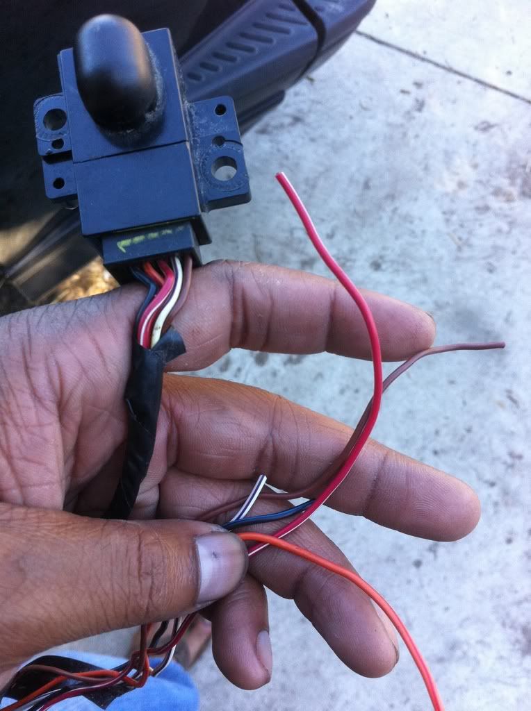
I have scoured my factory wiring manual and I am unable to identify the sensor you picture.
The manual does not show a component with the wires shown in a '04-'08.
I may have missed it.
Are you sure that the object came from a '05?
The manual does not show a component with the wires shown in a '04-'08.
I may have missed it.
Are you sure that the object came from a '05?
Thread Starter
|
Senior User
Joined: Jul 2011
Posts: 306
Likes: 0
From: 1000k oaks or SanFernando
yep I stole it from my old truck. It on the dash of all xlts and above it blinks red at night when you get out of it. But most importantly it senses the light if it gets dark the lights turn on.
Postmaster
Joined: Jul 2010
Posts: 3,743
Likes: 2
From: Henrico, VA
That is not what turns the lights on when it gets dark out that is the sensor for the key fob. The sensor that picks up when it gets dark out is up behind the rear view mirror. I have that sensor you are holding on my 2006 on the dash and it blinks red but only when I lock the doors from the key fob.
The sensor you are needing would of had a photocell on it and what you are holding does not. If you still have your old truck then raid it again as that one in your hand should be in your new truck already.
The sensor you are needing would of had a photocell on it and what you are holding does not. If you still have your old truck then raid it again as that one in your hand should be in your new truck already.
Thread Starter
|
Senior User
Joined: Jul 2011
Posts: 306
Likes: 0
From: 1000k oaks or SanFernando
I'm not sure if I agree 100% with that. Reasons why is 1) I use to put my license plate in the front left window and, I wondered why my lights where always on when I got out. 2) There is a post on another forum where people tape it with dark tape to get daytime running light.
If you have one turn your auto lamps on and cover it with your hand and in a few seconds your lights should turn on.
If you have one turn your auto lamps on and cover it with your hand and in a few seconds your lights should turn on.
Hotshot
Joined: Sep 2010
Posts: 10,459
Likes: 10
From: RVA
I'm not sure if I agree 100% with that. Reasons why is 1) I use to put my license plate in the front left window and, I wondered why my lights where always on when I got out. 2) There is a post on another forum where people tape it with dark tape to get daytime running light.
If you have one turn your auto lamps on and cover it with your hand and in a few seconds your lights should turn on.
If you have one turn your auto lamps on and cover it with your hand and in a few seconds your lights should turn on.
Thread Starter
|
Senior User
Joined: Jul 2011
Posts: 306
Likes: 0
From: 1000k oaks or SanFernando
Thanks Davis! Us Davis folk have to stick together. lol
Trending Topics
Postmaster
Joined: Jul 2010
Posts: 3,743
Likes: 2
From: Henrico, VA
OK so I was wrong they used to be behind the mirrors hadn't checked so figured it was still there.
On a side note next time don't send someone a PM that is just **** poor I check back here and always admit when I am wrong about something. If you are right it doesn't require a PM to prove it.
On a side note next time don't send someone a PM that is just **** poor I check back here and always admit when I am wrong about something. If you are right it doesn't require a PM to prove it.
FTE Stories
Ford Trucks for Ford Truck Enthusiasts

3 Best / 3 Worst Parts of Modern Ford Ownership
Brett Foote
10 Amazing Upgrades That Solve Common Ford Truck Owner Headaches
Pouria Savadkouei
Every 2026 Ford Engine Explained
Brett Foote
10 Ugly Ford Trucks That We Still Kinda Love
Joe Kucinski
10 Things Every Truck Owner NEEDS (2026 Edition)
Michael S. Palmer
Rezvani's Latest Post-Apocalyptic Monster Is a Ford F-150 Raptor Underneath
Verdad Gallardo
Top 10 Most Expensive Ford Trucks Ever Sold on Bring a Trailer
Joe Kucinski
2027 Ford Super Duty Buyer's Guide (Every Model, Engine, & Package)
Brett Foote
Top 10 Ford Truck Tragedies
Joe KucinskiHotshot
Joined: Sep 2010
Posts: 10,459
Likes: 10
From: RVA
OK so I was wrong they used to be behind the mirrors hadn't checked so figured it was still there.
On a side note next time don't send someone a PM that is just **** poor I check back here and always admit when I am wrong about something. If you are right it doesn't require a PM to prove it.
On a side note next time don't send someone a PM that is just **** poor I check back here and always admit when I am wrong about something. If you are right it doesn't require a PM to prove it.
ItsMREMT, if this is true, that's just poor stewardship on your part man. Those kinds of actions won't gain you too many friends around here.
Lead Driver


Joined: Sep 2007
Posts: 8,180
Likes: 669
From: Scio, OR

I'm not sure that sun load sensor will work. I've attached two diagrams. The first one is the diagram for a 2004 F-250. The F-250 sun load sensor is 3 wires, one ground, one to the VSM for the auto lamps and one to the EATC if you have it. They are simple photoelectric diodes that either pass current or make current (I'm not sure which) depending on the amount of light they receive.
The second diagram shows 2 of the wires going to the sensor you have. Other wires are power, ground and a wire for the security indicator light. That diagram indicates logic circuitry in the sensor itself that may not make it compatible.
I would hook a DVOM to the two wires shown (white with a violent stripe and black with a light blue stripe). See if their is current on those two wires when the sensor is in the sun vs when it is not in the sun, and see if their is resistance on those wires in the sun vs not in the sun.