


6.9l customization
Thread Starter
|
Elder User
Joined: Aug 2007
Posts: 589
Likes: 2
From: Nutter Fort,West Virginia
6.9l customization
i am currently building a 6.9l f350 1987. i plan to go though the entire truck and fix anything i consider needing repair or done a different way.
i plan to make a box for the batteries back on the frame on the frame right behind the cab so that there will be less weight jumping on the core support and help balance the truck ever so slightly more.
i will probably rearrange the engine bay so that the coolant/wiper fluid reservoir is on the passenger side so that i can put an air-filter on the driver side. all electronics will go in a container of some sort and all of the wires will be re-bundled(a basic tidy up). the truck does not have a air conditioning system. the turbo i plan on using is a t3-t4 out of a ATS kit and possibly upgrading the journal bearings to ball bearings.
now for the fun part, questions the exhaust. my father is trying to get me to make a power stroke like header and up pipe, i don't see a problem with this, but i want to make it the best that i can.
the ports coming out of the head are about 1/7/8" round. now from what i was reading on the garrett sight, they recommend a flow of 200-300 feet per second. if that is so, the velocity of air going though that 1/7/8" port is 88.3feet per second@ 14lbs of boost.
i am not sure what the valve lift is, but i am sure the air is moving faster though the valve than that.
once the charge gets back the the manifold's collector 2/1/4" the speed is back up to approximately 250 feet per second.
i was planning on making a new manifold that comes has nice 3 inch radius bents in a 1/7/8 pipe witch transitions into 2.25 and wraps around the end of the block going up to the turbo. i think this would smooth the flow a bunch except for it going fast-slow-moderate as it moves into the collector for that bank. should i down size the pipe size so that the flow stays more even?
also, on the down pipe i was going to make a new "exhaust flange". actually more or less get rid of the one it came with and totally remake my own. since i don't have the ac evaporator in my way i was going to run the down pipe outside of the frame close to the cab mount (there is enough room there for a 4" pipe), this would allow large bends and only really need two of them to get the enough past the rear of the cab.
the existing flang on the turbo looks to me like it created a bunch of turbulence right off the turbine wheel so i was going to run a pipe straight out of the turbine the same size as the exducer and taper it up to 3/3/4"(this will allow a velocity below 200 feet per second and streamline the flow out of the turbine). for the wategate i was going to make a second chamber that ran with the main pipe and blended in right before the bend turning the pipe downward.
the turbine housing has a step right at the end of the blades, does this step have any use? if not i would like to weld it up and turn it clean.
sorry if i am not clear, i hope that i have explained this well enough.

Posting Guru
Joined: Jul 2004
Posts: 1,627
Likes: 0
From: West Valley Utah
I'm not real clear on your idea. Are you saying you are going to build 1 exhaust manifold, I assume the right (passenger) side? Or you want to build a set of manifolds and bring the tubes around the rear of the engine?
I don't believe smoothing the step in the housing is going to make any difference. The turbo is already able to make more boost than the engine can dependably take.
I don't believe smoothing the step in the housing is going to make any difference. The turbo is already able to make more boost than the engine can dependably take.

Elder User
Joined: Sep 2007
Posts: 662
Likes: 0
i am currently building a 6.9l f350 1987. i plan to go though the entire truck and fix anything i consider needing repair or done a different way.
i plan to make a box for the batteries back on the frame on the frame right behind the cab so that there will be less weight jumping on the core support and help balance the truck ever so slightly more.
i will probably rearrange the engine bay so that the coolant/wiper fluid reservoir is on the passenger side so that i can put an air-filter on the driver side. all electronics will go in a container of some sort and all of the wires will be re-bundled(a basic tidy up). the truck does not have a air conditioning system. the turbo i plan on using is a t3-t4 out of a ATS kit and possibly upgrading the journal bearings to ball bearings.
now for the fun part, questions the exhaust. my father is trying to get me to make a power stroke like header and up pipe, i don't see a problem with this, but i want to make it the best that i can.
the ports coming out of the head are about 1/7/8" round. now from what i was reading on the garrett sight, they recommend a flow of 200-300 feet per second. if that is so, the velocity of air going though that 1/7/8" port is 88.3feet per second@ 14lbs of boost.
i am not sure what the valve lift is, but i am sure the air is moving faster though the valve than that.
once the charge gets back the the manifold's collector 2/1/4" the speed is back up to approximately 250 feet per second.
i was planning on making a new manifold that comes has nice 3 inch radius bents in a 1/7/8 pipe witch transitions into 2.25 and wraps around the end of the block going up to the turbo. i think this would smooth the flow a bunch except for it going fast-slow-moderate as it moves into the collector for that bank. should i down size the pipe size so that the flow stays more even?
also, on the down pipe i was going to make a new "exhaust flange". actually more or less get rid of the one it came with and totally remake my own. since i don't have the ac evaporator in my way i was going to run the down pipe outside of the frame close to the cab mount (there is enough room there for a 4" pipe), this would allow large bends and only really need two of them to get the enough past the rear of the cab.
the existing flang on the turbo looks to me like it created a bunch of turbulence right off the turbine wheel so i was going to run a pipe straight out of the turbine the same size as the exducer and taper it up to 3/3/4"(this will allow a velocity below 200 feet per second and streamline the flow out of the turbine). for the wategate i was going to make a second chamber that ran with the main pipe and blended in right before the bend turning the pipe downward.
the turbine housing has a step right at the end of the blades, does this step have any use? if not i would like to weld it up and turn it clean.
sorry if i am not clear, i hope that i have explained this well enough.
i plan to make a box for the batteries back on the frame on the frame right behind the cab so that there will be less weight jumping on the core support and help balance the truck ever so slightly more.
i will probably rearrange the engine bay so that the coolant/wiper fluid reservoir is on the passenger side so that i can put an air-filter on the driver side. all electronics will go in a container of some sort and all of the wires will be re-bundled(a basic tidy up). the truck does not have a air conditioning system. the turbo i plan on using is a t3-t4 out of a ATS kit and possibly upgrading the journal bearings to ball bearings.
now for the fun part, questions the exhaust. my father is trying to get me to make a power stroke like header and up pipe, i don't see a problem with this, but i want to make it the best that i can.
the ports coming out of the head are about 1/7/8" round. now from what i was reading on the garrett sight, they recommend a flow of 200-300 feet per second. if that is so, the velocity of air going though that 1/7/8" port is 88.3feet per second@ 14lbs of boost.
i am not sure what the valve lift is, but i am sure the air is moving faster though the valve than that.
once the charge gets back the the manifold's collector 2/1/4" the speed is back up to approximately 250 feet per second.
i was planning on making a new manifold that comes has nice 3 inch radius bents in a 1/7/8 pipe witch transitions into 2.25 and wraps around the end of the block going up to the turbo. i think this would smooth the flow a bunch except for it going fast-slow-moderate as it moves into the collector for that bank. should i down size the pipe size so that the flow stays more even?
also, on the down pipe i was going to make a new "exhaust flange". actually more or less get rid of the one it came with and totally remake my own. since i don't have the ac evaporator in my way i was going to run the down pipe outside of the frame close to the cab mount (there is enough room there for a 4" pipe), this would allow large bends and only really need two of them to get the enough past the rear of the cab.
the existing flang on the turbo looks to me like it created a bunch of turbulence right off the turbine wheel so i was going to run a pipe straight out of the turbine the same size as the exducer and taper it up to 3/3/4"(this will allow a velocity below 200 feet per second and streamline the flow out of the turbine). for the wategate i was going to make a second chamber that ran with the main pipe and blended in right before the bend turning the pipe downward.
the turbine housing has a step right at the end of the blades, does this step have any use? if not i would like to weld it up and turn it clean.
sorry if i am not clear, i hope that i have explained this well enough.
it sounds like you want to use a stock turbo? why they suck and are junk any stock system is. im building an hx35/40 hybrid to go on my truck that will be wged at 17 psi to start with but the system will support up to 30 psi with the right mods.
1 7/8 will do good dont neck down you want more velocity to spool lower and less to spool higher this will allow you to put the power where you want it
also the uppipe at 2.5 inch is fine any larger youll have lag
also post a link to the turbo you want to use not all t3s are the same
heres some info for ya including valve lift
6.9 4.00 7.3 4.11 bore
4.18 stroke
6.9 4000 rpm 840000 cu in/min
486.1111111 cu ft/min
exhaust port 1 7/8 inch round
stock
rocker arms 1.5 ratio stock
60 thousands valve to piston clearance
intake lift on cam .2535
exhaust lift on cam .2531
lift at valve
intake .38025
exhaust .37965
and make the dp itll be a lot better to have it how and where you want
idk how you plan to fit a 4 inch down there im going to run a 3 inch dp in the same area and it seems to be a very close fit are you clearencing stuff?
the best way to mount is on top of the motor with equal length uppipes going into their respective halves of a divided inlet turbo
this is my build thread so take a look and feel free to use the ideas
my turbo build thread and other junkm pic heavy - Oilburners.net
Thread Starter
|
Elder User
Joined: Aug 2007
Posts: 589
Likes: 2
From: Nutter Fort,West Virginia
yes, each bank would curve around and meet up in the middle. both manifolds would have to be made to get a good bend going back up the the turbo.
i am trying to get it to spool faster and have less drag. my fathers truck runs up to 27 psi with the t3/t4 that comes with the ats kit. (more than i will be running until i have to tear the engine down for whatever reason.)
as for the battery cables, isn't it about the same distance? i measure about 4 and 5 feet one leading into the other and to the rear of the cab from the starter is about 7 feet. i was going to run a pair of 00 or 000 stranded copper (like for an entrance main or a good cable for a welder that is suitable for 600 amps)
and from what i was getting the velocity would be just about right at wide open at 14 psi boost in a 2.25 pipe (for the collector on each bank, the up pipe). however the velocity is too slow in the manifold and out of the ports (probably to compensate for the double 90* bends back to back)
i can fit a 4" down the out side of the frame(though the wheel well) and i should have plenty of clearance hard right with the suspension fully compressed (even with larger tires)
i am going to rewire the entire truck with larger wires
what diameter are the valves?
what do you think about my idea for the "exhaust flange/waste gate"?
Elder User
Joined: Sep 2007
Posts: 662
Likes: 0
well it seems to spool fast and have less drag a smaller turbo would do good just dont let it choke out a stock turbo will choke out very easy making boost
youre battery cable plans seem to work
dont know dia off hand and dont have an apart motor at this point to measure
this is a model car im building to have an idi not too detailed but enough to reconize it
heres a pic youre thinking of doing something like this but mount the turbo in the middle?
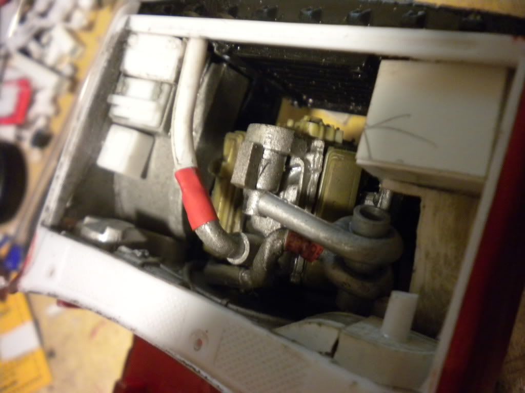
if so you can run the dp out side the frame it wont take much just turn it a bit
youre battery cable plans seem to work
dont know dia off hand and dont have an apart motor at this point to measure
this is a model car im building to have an idi not too detailed but enough to reconize it
heres a pic youre thinking of doing something like this but mount the turbo in the middle?
if so you can run the dp out side the frame it wont take much just turn it a bit
Postmaster


Joined: Dec 2004
Posts: 2,941
Likes: 30
From: Maple Valley, WA
well it seems to spool fast and have less drag a smaller turbo would do good just dont let it choke out a stock turbo will choke out very easy making boost
youre battery cable plans seem to work
dont know dia off hand and dont have an apart motor at this point to measure
this is a model car im building to have an idi not too detailed but enough to reconize it
heres a pic youre thinking of doing something like this but mount the turbo in the middle?
if so you can run the dp out side the frame it wont take much just turn it a bit
Trending Topics
Thread Starter
|
Elder User
Joined: Aug 2007
Posts: 589
Likes: 2
From: Nutter Fort,West Virginia
he seems to be great at modeling.
na, i was going to have the axis of the turbine perpendicular with the axis of the crank and sit it right behind the intake manifold opening (turbine housing lightly more towards the front passenger). kinda like the banks kit i suppose.
by choke out you mean stall or over speed?
na, i was going to have the axis of the turbine perpendicular with the axis of the crank and sit it right behind the intake manifold opening (turbine housing lightly more towards the front passenger). kinda like the banks kit i suppose.
by choke out you mean stall or over speed?
FTE Stories
Ford Trucks for Ford Truck Enthusiasts

10 Things Every Truck Owner NEEDS (2026 Edition)
Michael S. Palmer
Rezvani's Latest Post-Apocalyptic Monster Is a Ford F-150 Raptor Underneath
Verdad Gallardo
Top 10 Most Expensive Ford Trucks Ever Sold on Bring a Trailer
Joe Kucinski
2027 Ford Super Duty Buyer's Guide (Every Model, Engine, & Package)
Brett Foote
Top 10 Ford Truck Tragedies
Joe Kucinski
AEV FXL Super Duty - the Super Duty Raptor Ford Doesn't Make
Brett Foote
Lobo Vs Lobo: Proof the F-150 Lobo Should Be Even Lower!
Michael S. Palmer
Ford's 2001 Explorer Sportsman Concept Looks For a New Home
Verdad Gallardo
10 Best Ford Truck Engines We Miss the Most!
Joe Kucinski
Elder User
Joined: Sep 2007
Posts: 662
Likes: 0
perpendicular with crank wont work in most turbos due to oil flow but there may be some that will
the pipes i used were about the same length if not joined together where the turbo is get some thick wire and mock up and measure
but id keep the axis parallel to the crank in youre plans
the pipes i used were about the same length if not joined together where the turbo is get some thick wire and mock up and measure
but id keep the axis parallel to the crank in youre plans
Thread Starter
|
Elder User
Joined: Aug 2007
Posts: 589
Likes: 2
From: Nutter Fort,West Virginia
??? how would that affect oil flow? (perpendicular as if you are looking down on the truck, not from the side.)
i need to do a sketch or mock up
i also need to come across a zf5
i need to do a sketch or mock up
i also need to come across a zf5
Thread Starter
|
Elder User
Joined: Aug 2007
Posts: 589
Likes: 2
From: Nutter Fort,West Virginia
compressor
inducer 59mm
exducer 70mm
trim 69
.7 a/r
turbine
inducer 64mm
exducer 58mm
trim 121?
a/r ... 28??? that can't be right can it? (37 if the scroll was square in shape)
inducer 59mm
exducer 70mm
trim 69
.7 a/r
turbine
inducer 64mm
exducer 58mm
trim 121?
a/r ... 28??? that can't be right can it? (37 if the scroll was square in shape)
Thread Starter
|
Elder User
Joined: Aug 2007
Posts: 589
Likes: 2
From: Nutter Fort,West Virginia
new question i plan on putting an air compressor on this truck. what would happen if i put a small jet into the exhaust manifold facing down stream as to blow the exhaust down stream and add air into the exhaust?
i would think it would make very little difference to the turbo chariteristics until i started blowing smoke. at that point it should reignite the left over fuel should it not?
= larg increase of drive force on the turbine at the cost of egts?
i would think it would make very little difference to the turbo chariteristics until i started blowing smoke. at that point it should reignite the left over fuel should it not?
= larg increase of drive force on the turbine at the cost of egts?
Thread Starter
|
Elder User
Joined: Aug 2007
Posts: 589
Likes: 2
From: Nutter Fort,West Virginia
GTX3071r is what i am coming up with for a turbo.
TurboByGarrett.com - Catalog
at 22lbs of boost and bouncing off the revlimiter i would be pushing something like 47.1 lbs of air/minute at a pressure ratio of about 1.5
correct me if i am wrong please
and what makes you want to go with holset?
TurboByGarrett.com - Catalog
at 22lbs of boost and bouncing off the revlimiter i would be pushing something like 47.1 lbs of air/minute at a pressure ratio of about 1.5
correct me if i am wrong please
and what makes you want to go with holset?
Thread Starter
|
Elder User
Joined: Aug 2007
Posts: 589
Likes: 2
From: Nutter Fort,West Virginia
a change again now thinking about going with a gtx3582r.
turbonetics suggests a 64mm compressor inducer and a 65mm turbine with a .84 a/r
$1284 for the ball bearing unit from turbonetics (are they any good verses garrett?)
the gtx will run $1750 + turbine housing (estimated) $400
turbonetics suggests a 64mm compressor inducer and a 65mm turbine with a .84 a/r
$1284 for the ball bearing unit from turbonetics (are they any good verses garrett?)
the gtx will run $1750 + turbine housing (estimated) $400
Postmaster
Joined: Aug 2010
Posts: 2,554
Likes: 7
From: Northern Arizona
Are you thinking about a performance cam grind? There are a couple of threads on this forum that have me pretty convinced that the cam is s serious bottleneck for these engines. When I build mine I will definitely go that route, I'm just not sure whether I want Typ4's low end "torque cam" that pulls really hard at 1200 rpm or the Delta 206-2 grind that 91dirtydiesel has that delivers in the 2100-2200 range. Don't know how that fits in with your elaborate turbo plans, just curious what other guys are doing with their cams...