





Duraspark II/HEI conversion failed

Thread Starter
|
Freshman User
Joined: Jun 2011
Posts: 29
Likes: 0
Duraspark II/HEI conversion failed
I will try to give the shortest version of this that I can. The engine this refers to is the good ole 300 i6. Yesterday I attempted to place a 4-pin HEI module on my truck, because the ballast resistor I had been using on my Duraspark II setup burned in half. Many folks are talking about the HEI setup, and I have heard few negatives about it. Here is my story, perhaps someone can help.
The schematic I used is as follows:
Module pin details:
B = HEI module power in and coil + terminal power in
C = HEI module to coil - and tach
W = HEI module to DSII stator orange
G = HEI module to DSII stator green
I wired everything up with the proper terminals using this exact arrangement except my B terminal connection does not feed off of the coil + terminal as a bus location. Rather, my ignition switch feeds both the module and the coil + from a T-junction right outside the firewall (shouldn't matter, my duraspark was like that too and lots of chrysler boys do it that way).
Specific parts used in the experiments:
 BWD control module CBE4Z from Advance Auto (because they didn't have any of the better ones in stock)
14 gauge primary wires of different colors
crimp connectors: 1/4" female on pins B, C, and W and 3/16" female on G
 Cardone reman DSII distributor that was put on the truck over a year ago for a 1981 F100.
 bread loaf pan was drilled such that the 8/32 screws used for the module actually screwed in. This was to be my makeshift heat sink, because it is dreadfully difficult to find a spot to mount the HEI on my 86 F150, and porper heat sinks were not to be found in BFE where I live. Lack of resources and creativity are close cousins.
These were the initial pieces I selected to run the experiements, with the idea that I would get a better heat sink and pay shipping costs for one if it was worth my time.
The experiments:
The module was mounted to the bread pan which was in turn bolted to the plastic inner fender well just between the DSII module and the wash/radiator overflow bottle. The wiring was set up as per the diagram above with only the mentioned T-junction arrangement of the supply voltage circuit as a midification. Everything looked neat and proper, so the key was turned. A no-fire condition was confirmed by a spark tester following several disappointing attempts to fire the engine. A voltmeter was hooked to the supply voltage circuit to determine potential vs. key position, just to be sure (I already knew this was fine due to the duraspark conversion I did from EEC-IV the previous year, but better safe than sorry). I also did other critical voltmeter tests.
Key position test:
Run position = 12.6V @ module B + and 12.6V @ coil +
Start position = exactly the same as run
The basic primary voltage was fine and active in both critical key positions.
Module power and ground:
The negative voltmeter lead was touched to the screw where the black wire to the distributor base was connected, and the positive lead to the module B+. 12.6V
The module was powered up and grounded.
Module power and ground rework:
direct battery terminal + and - connections were run to the module with test wires and gator clips. The coil + was also included. Cranked it and no spark.
Duraspark II module test run: To inspect the integrity of the orange and purple stator connections, the original DSII module was hooked up with the exact same wires that were in place on the HEI module. The 4-pin DSII module plug recieved the wiring from HEI in this specific fashion:
HEI C terminal to coil - was hooked to DSII green lead
HEI B terminal to coil + was hooked to DSII white power in
HEI W orange lead was conncted to DSII orange stator lead
HEI G purple lead was connected to DSII purple lead
HEI distributor ground was hooked to DSII black lead with a gator clip
Key was turned and the engine fired up and ran perfectly within 1/2 second.
HEI double ground: a whole was drilled in the cake pan which tested 0.00 ohms in a continuity test to determine conductivity. The whole was connected by a lead to the battery negative terminal to provide ground connectivity across the entire back of the HEI module (assuming that the heat sink compound is conductive. Again no spark.
HEI module replacement: The module was taken back to Advance and swapped for a new one. Again, no spark.
Conclusion: The BWD HEI module cannot communicate with the cardone reman stator to complete the ignition firing circuit.
Does anyone know what the hell is going on here? Have I missed something? Any input will be appreciated.
I hooked the DSII back up, because the truck is my daily driver, and I cannot be without it. It still does not have the ballst resistor. The coil I am using is this:
 MSD street fire (PN 5527)
This coil is available for all the later model TFI and EFI Ford motors that didn't use ballasts, and the input voltage is rated for 12 V. To me that means that the ballast is not necessary, because the coil has its own built in resistance. The DSII module runs a constant 12 V anyway, so I figure I might just say the hell with the HEI mod as long as this coil is going to survive a no-ballst condition. There are tons of confliciting reoprts on the internet in regard to whether or not coils and modules for DSII live through the no-ballast scenario, but it seems to me that if the coil has its own internal resistance built in, then there is no need to worry since firing power is going to be normalized to the same thing. That being said, what thoughts do we have out there regarding this topoc in general? Is it even worth it to bother with the HEI since it didn't work for me, and the DSII is a fine ignition anyway? Thanks folks.
The schematic I used is as follows:
Module pin details:
B = HEI module power in and coil + terminal power in
C = HEI module to coil - and tach
W = HEI module to DSII stator orange
G = HEI module to DSII stator green
I wired everything up with the proper terminals using this exact arrangement except my B terminal connection does not feed off of the coil + terminal as a bus location. Rather, my ignition switch feeds both the module and the coil + from a T-junction right outside the firewall (shouldn't matter, my duraspark was like that too and lots of chrysler boys do it that way).
Specific parts used in the experiments:
BWD control module CBE4Z from Advance Auto (because they didn't have any of the better ones in stock)14 gauge primary wires of different colors
crimp connectors: 1/4" female on pins B, C, and W and 3/16" female on G
Cardone reman DSII distributor that was put on the truck over a year ago for a 1981 F100.bread loaf pan was drilled such that the 8/32 screws used for the module actually screwed in. This was to be my makeshift heat sink, because it is dreadfully difficult to find a spot to mount the HEI on my 86 F150, and porper heat sinks were not to be found in BFE where I live. Lack of resources and creativity are close cousins.These were the initial pieces I selected to run the experiements, with the idea that I would get a better heat sink and pay shipping costs for one if it was worth my time.
The experiments:
The module was mounted to the bread pan which was in turn bolted to the plastic inner fender well just between the DSII module and the wash/radiator overflow bottle. The wiring was set up as per the diagram above with only the mentioned T-junction arrangement of the supply voltage circuit as a midification. Everything looked neat and proper, so the key was turned. A no-fire condition was confirmed by a spark tester following several disappointing attempts to fire the engine. A voltmeter was hooked to the supply voltage circuit to determine potential vs. key position, just to be sure (I already knew this was fine due to the duraspark conversion I did from EEC-IV the previous year, but better safe than sorry). I also did other critical voltmeter tests.
Key position test:
Run position = 12.6V @ module B + and 12.6V @ coil +
Start position = exactly the same as run
The basic primary voltage was fine and active in both critical key positions.
Module power and ground:
The negative voltmeter lead was touched to the screw where the black wire to the distributor base was connected, and the positive lead to the module B+. 12.6V
The module was powered up and grounded.
Module power and ground rework:
direct battery terminal + and - connections were run to the module with test wires and gator clips. The coil + was also included. Cranked it and no spark.
Duraspark II module test run: To inspect the integrity of the orange and purple stator connections, the original DSII module was hooked up with the exact same wires that were in place on the HEI module. The 4-pin DSII module plug recieved the wiring from HEI in this specific fashion:
HEI C terminal to coil - was hooked to DSII green lead
HEI B terminal to coil + was hooked to DSII white power in
HEI W orange lead was conncted to DSII orange stator lead
HEI G purple lead was connected to DSII purple lead
HEI distributor ground was hooked to DSII black lead with a gator clip
Key was turned and the engine fired up and ran perfectly within 1/2 second.
HEI double ground: a whole was drilled in the cake pan which tested 0.00 ohms in a continuity test to determine conductivity. The whole was connected by a lead to the battery negative terminal to provide ground connectivity across the entire back of the HEI module (assuming that the heat sink compound is conductive. Again no spark.
HEI module replacement: The module was taken back to Advance and swapped for a new one. Again, no spark.
Conclusion: The BWD HEI module cannot communicate with the cardone reman stator to complete the ignition firing circuit.
Does anyone know what the hell is going on here? Have I missed something? Any input will be appreciated.
I hooked the DSII back up, because the truck is my daily driver, and I cannot be without it. It still does not have the ballst resistor. The coil I am using is this:
MSD street fire (PN 5527)This coil is available for all the later model TFI and EFI Ford motors that didn't use ballasts, and the input voltage is rated for 12 V. To me that means that the ballast is not necessary, because the coil has its own built in resistance. The DSII module runs a constant 12 V anyway, so I figure I might just say the hell with the HEI mod as long as this coil is going to survive a no-ballst condition. There are tons of confliciting reoprts on the internet in regard to whether or not coils and modules for DSII live through the no-ballast scenario, but it seems to me that if the coil has its own internal resistance built in, then there is no need to worry since firing power is going to be normalized to the same thing. That being said, what thoughts do we have out there regarding this topoc in general? Is it even worth it to bother with the HEI since it didn't work for me, and the DSII is a fine ignition anyway? Thanks folks.
Thread Starter
|
Freshman User
Joined: Jun 2011
Posts: 29
Likes: 0
Module pin details:
B = HEI module power in and coil + terminal power in
C = HEI module to coil - and tach
W = HEI module to DSII stator orange
G = HEI module to DSII stator purple
that should say purple on pin G above
B = HEI module power in and coil + terminal power in
C = HEI module to coil - and tach
W = HEI module to DSII stator orange
G = HEI module to DSII stator purple
that should say purple on pin G above
Thread Starter
|
Freshman User
Joined: Jun 2011
Posts: 29
Likes: 0
About the MSD chinese built street fire coil, I can answer my own question. I drove the truck to the gym and then back home. Before I could pull it into the garage, it died and would restart briefly before dying again. The module and coil were very hot. The ballast is needed, even with the TFI type E coils, to prevent overheating apparently. Now I really need somebody to demytify why the HEI mod didn't work for me, because I am walking. I am not sure what all I am in for replacing, but I am not willing to buy the bulk of the DSII again. I'd rather just eat th cost of the DUI setup (which is what I was trying to accomplish more chaeply with the HEI module experiment). Thanks for any help.

Cranky Old Guy
Joined: Mar 2008
Posts: 3,562
Likes: 6
From: Raphine, Virginia
One question. The ballast resistor you said burnt up, was it a ballast resistor on firewall or the resistor wire that is behind the dash connected to ignition switch? If that wire was not removed it would cause both your problems.
Cargo Master


Joined: Mar 2008
Posts: 2,577
Likes: 211
From: Washington
Good post. Well written with lots of good trouble shooting already done.
The ballast resistor will drop the current flow in half. The street fire coil most likely will have about half the primary resistance as an old round coil, which will double the current flow.
So your current flow is about 4 times the stock IGN system DS2 module was meant to handle. Thus a HOT DS2 module.
The only ideas I have on getting the 4 pin module to work is be sure and add an extra ground on the mounting screw the has the metal inside it. It is on the left in your photo.
Also try swapping the to stator wires on the 4 pin module to see if it helps.
To get the DS2 module back on line you will ballast resistor to lower current flow to the DS2 module. An old round coil would also help as it has a higher primary resistance, 1.2 ohm,
The ballast resistor should be close to equal the coil primary resistance, to divide the supply voltage equally, 6v and 6 volt.
A 1.2 ohm ballast with a .6 ohm coil PRI will only leave 1/3 of the supply voltage to the coil positive. Say 8 Volts and 4 volts split. It might not run with 4 volts supplying the coil.
Jim
The ballast resistor will drop the current flow in half. The street fire coil most likely will have about half the primary resistance as an old round coil, which will double the current flow.
So your current flow is about 4 times the stock IGN system DS2 module was meant to handle. Thus a HOT DS2 module.
The only ideas I have on getting the 4 pin module to work is be sure and add an extra ground on the mounting screw the has the metal inside it. It is on the left in your photo.
Also try swapping the to stator wires on the 4 pin module to see if it helps.
To get the DS2 module back on line you will ballast resistor to lower current flow to the DS2 module. An old round coil would also help as it has a higher primary resistance, 1.2 ohm,
The ballast resistor should be close to equal the coil primary resistance, to divide the supply voltage equally, 6v and 6 volt.
A 1.2 ohm ballast with a .6 ohm coil PRI will only leave 1/3 of the supply voltage to the coil positive. Say 8 Volts and 4 volts split. It might not run with 4 volts supplying the coil.
Jim
Thread Starter
|
Freshman User
Joined: Jun 2011
Posts: 29
Likes: 0
gfw, the ballast was a ceramic body aftermarket type like the chrysler units. It was firewall mounted.
Trending Topics
Thread Starter
|
Freshman User
Joined: Jun 2011
Posts: 29
Likes: 0
Thanks JimsRebel. I should have posted also that I switched pins W and G on the HEI to see if it would hit. No spark there either. It makes sense that I should be using a round coil like the normal DS II unit. I'll get that hooked up in the meantime. I'm really stumped about the HEI. I'll try the double ground through both bolt holes and see if it hits.
FTE Stories
Ford Trucks for Ford Truck Enthusiasts

Top 6 Best Deals Available on New Fords & Lincolns Right Now
Brett Foote
This Hennessey Takes the Expedition Tremor's Off-Roading Capability to the Next Level
Verdad Gallardo
Top 10 Fords at 2026 Carlisle Ford Nationals
Joe Kucinski
3 Best / 3 Worst Parts of Modern Ford Ownership
Brett Foote
10 Amazing Upgrades That Solve Common Ford Truck Owner Headaches
Pouria Savadkouei
Every 2026 Ford Engine Explained
Brett Foote
10 Ugly Ford Trucks That We Still Kinda Love
Joe Kucinski
10 Things Every Truck Owner NEEDS (2026 Edition)
Michael S. Palmer
Rezvani's Latest Post-Apocalyptic Monster Is a Ford F-150 Raptor Underneath
Verdad Gallardo
Cargo Master
Joined: Mar 2008
Posts: 2,577
Likes: 211
From: Washington
In the photo below you will see a black ground wire connected to the GM 4 pin module at "its" grounding point.
The photo was taken at first intall/testing. I had consider the ground wire extra and really not needed as it was well grounded to the metal engine attachment. I disconnected the knife connector at idle and the engine quit.
.
.
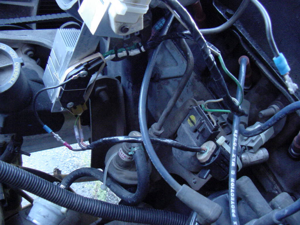
The photo was taken at first intall/testing. I had consider the ground wire extra and really not needed as it was well grounded to the metal engine attachment. I disconnected the knife connector at idle and the engine quit.
.
.
Thread Starter
|
Freshman User
Joined: Jun 2011
Posts: 29
Likes: 0
Tonight I hooked everything back up and double grounded the HEI module through both bolt holes. I also grounded the heat sink to the battery negative terminal. No spark.
There has to be some untold disparity between the BWD module and the cardone reman stator. Everything else is hot and ready to pour the coals.
Anyway, I am frustrated to death now. I went and bought another ballast resistor and DSII module. I'm just going to hook the stock ignition back up. HEI is not working on my truck, and I have no idea why. I did everything to spec and followed all the advice so far. Unless I got two bum HEI modules in a row (unlikely), the cardone reman stator and the BWD HEI module simply do not communicate.
There has to be some untold disparity between the BWD module and the cardone reman stator. Everything else is hot and ready to pour the coals.
Anyway, I am frustrated to death now. I went and bought another ballast resistor and DSII module. I'm just going to hook the stock ignition back up. HEI is not working on my truck, and I have no idea why. I did everything to spec and followed all the advice so far. Unless I got two bum HEI modules in a row (unlikely), the cardone reman stator and the BWD HEI module simply do not communicate.
Thread Starter
|
Freshman User
Joined: Jun 2011
Posts: 29
Likes: 0
What kind of ditributors are you guys running? Motorcraft? There has to be something with the stator and HEI. I want to work this out for a fact so I can report to the community and tell folks which stators to avoid. I know this has to work, because you guys are running it. It's bothering me!



Thread Starter
|
Freshman User
Joined: Jun 2011
Posts: 29
Likes: 0
Duraspark didn't come stock on my truck. EEC-IV did. Both have been problematic. The HEI appeals to me, because I have had trouble with ballst resistors regardless of coil choice. I like the DSII fine except for the ballast. Many people run the HEI and like it. It doesn't matter that the firepower is similar between HEI and DSII. Losing the ballast resistor is good enough for me. Of course, we are all entitled to our own opinions. I don't dislike GM, so I have no beef with using their ignition pieces.