
KOEO code assistance por favor!
#1
 02-07-2017, 07:33 PM

Join Date: Jan 2017
Location: Dallas-Ft Worth
Posts: 146
Likes: 0
Received 0 Likes
on
0 Posts
KOEO code assistance por favor!
Hey fellas,
I finally got my truck timed properly and it seems to be running very well, with the possible exception of a few stutters here any there...and the CEL being on.
That said, today I ran the KOEO test along with the Continuous Memory test and I got a few codes that I could use some assistance on.
During the KOEO test I received:
Code 553 - Air Management Circuit 2 Failure
I know that the Code 553 issue is likely because the PO removed the Smog Pump, and probably the other components as well...I need to get this truck to pass emissions so I'm guessing that I'll need to reassemble/install this system?
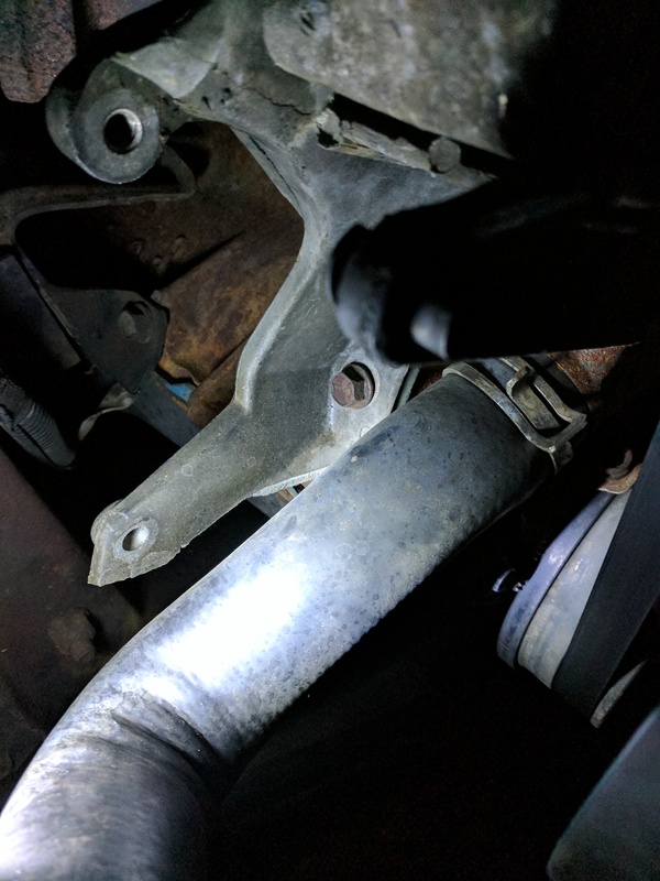
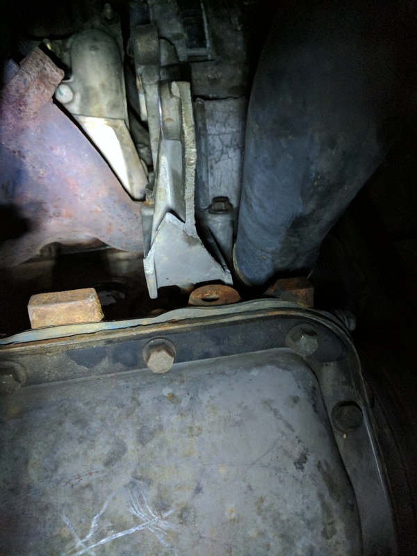
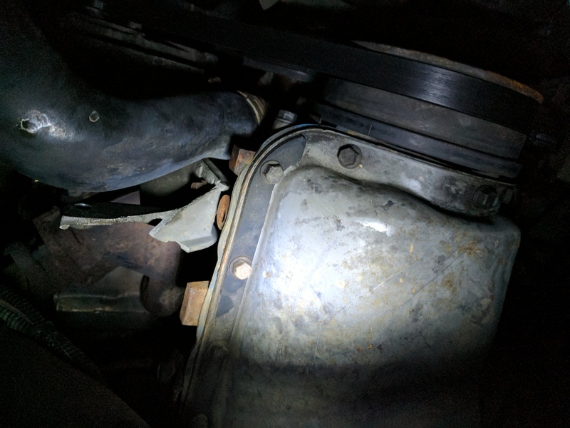
Additionally, when I was setting the timing yesterday, I noticed that the Smog Pump bracket is broken off (ie, I can see where the metal has been shattered off). I think this is the same bracket that holds the alternator? I've put some links below. What all parts do I need to get a functioning Air Injection system going again?
Continuous Memory Test:
Code 172 - HEGO (HO2S Sensor Fault/Lean)
Code 332 - Insufficient EGR Flow Detected
I'm thinking Code 172 may be getting thrown due to the Air Pump missing? Or could there be another issue?
On Code 332 - I'm thinking I just need to replace the EGR valve?
Thanks fellas!
-Matt
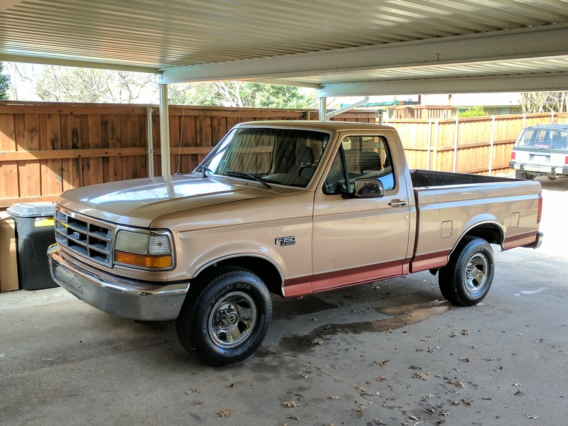
PS, shameless shot of her all cleaned up!
I finally got my truck timed properly and it seems to be running very well, with the possible exception of a few stutters here any there...and the CEL being on.
That said, today I ran the KOEO test along with the Continuous Memory test and I got a few codes that I could use some assistance on.
During the KOEO test I received:
Code 553 - Air Management Circuit 2 Failure
I know that the Code 553 issue is likely because the PO removed the Smog Pump, and probably the other components as well...I need to get this truck to pass emissions so I'm guessing that I'll need to reassemble/install this system?
Additionally, when I was setting the timing yesterday, I noticed that the Smog Pump bracket is broken off (ie, I can see where the metal has been shattered off). I think this is the same bracket that holds the alternator? I've put some links below. What all parts do I need to get a functioning Air Injection system going again?


Continuous Memory Test:
Code 172 - HEGO (HO2S Sensor Fault/Lean)
Code 332 - Insufficient EGR Flow Detected
I'm thinking Code 172 may be getting thrown due to the Air Pump missing? Or could there be another issue?
On Code 332 - I'm thinking I just need to replace the EGR valve?


Thanks fellas!
-Matt
PS, shameless shot of her all cleaned up!

#2
02-08-2017, 04:29 AM
Logistics Pro
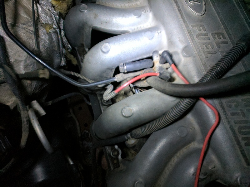
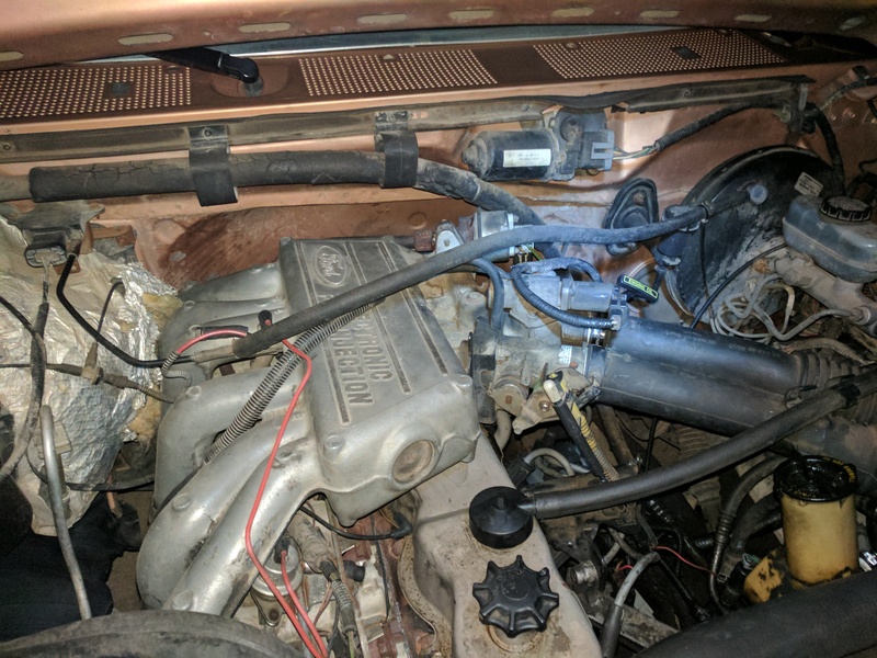
From the picture showing a "SCREW" shoved into a small piece of vacuum tubing suggests a Vacuum leak.
And it looks like all the vacuum lines are original...That being said...
Code 172 is probably, if not due to a vacuum leak. You need to test all vacuum lines and if it were me, I would replace ALL of them with some new vacuum tubing.
And it looks like all the vacuum lines are original...That being said...
Code 172 is probably, if not due to a vacuum leak. You need to test all vacuum lines and if it were me, I would replace ALL of them with some new vacuum tubing.
#3
02-08-2017, 08:18 AM
Join Date: Jan 2017
Location: Dallas-Ft Worth
Posts: 146
Likes: 0
Received 0 Likes
on
0 Posts
From the picture showing a "SCREW" shoved into a small piece of vacuum tubing suggests a Vacuum leak.
And it looks like all the vacuum lines are original...That being said...
Code 172 is probably, if not due to a vacuum leak. You need to test all vacuum lines and if it were me, I would replace ALL of them with some new vacuum tubing.
And it looks like all the vacuum lines are original...That being said...
Code 172 is probably, if not due to a vacuum leak. You need to test all vacuum lines and if it were me, I would replace ALL of them with some new vacuum tubing.
That said, should I try to source parts for the Air Pump system? Will that help to clear any codes? Does having the missing air pump have anything to do with the O2 sensor code or is it worthwhile to change out the O2 sensor for good measure? I hate to throw money at parts for no reason.
#4
02-08-2017, 08:28 AM
You miss read the 332 CM code.
Continuous Memory DTC 332 indicates the EGR valve did not open with the engine stabilized and the EVR solenoid duty cycle present sometime during vehicle operation.
Possible causes:
-- Obstructed or cracked hose to EGR valve.
-- Icing.
-- Damaged EGR valve.
-- Damaged EVR solenoid harness.
Key off.
Disconnect vacuum hose at EGR valve and connect a hand vacuum pump.
Apply 10-20 in-Hg (34-67 kPa) to EGR valve.
Does EGR valve open and maintain vacuum?
#5
02-08-2017, 09:43 AM

Replace your vacuum lines, and inspect your vacuum canisters and repair/replace as needed then see where you stand on codes. A hand vacuum pump is very useful for testing vacuum circuits and components.
On the AIR system, all it does is supply extra air for better catalytic converter operation under certain conditions. If you want to do things properly you have 2 options as I see it. You can restore the whole system, I would find a donor to do this, or you can install a converter that does not require an AIR system for proper operation.
On the AIR system, all it does is supply extra air for better catalytic converter operation under certain conditions. If you want to do things properly you have 2 options as I see it. You can restore the whole system, I would find a donor to do this, or you can install a converter that does not require an AIR system for proper operation.
#6
02-08-2017, 10:30 AM
Join Date: Jan 2017
Location: Dallas-Ft Worth
Posts: 146
Likes: 0
Received 0 Likes
on
0 Posts
You miss read the 332 CM code.
Continuous Memory DTC 332 indicates the EGR valve did not open with the engine stabilized and the EVR solenoid duty cycle present sometime during vehicle operation.
Possible causes:
-- Obstructed or cracked hose to EGR valve.
-- Icing.
-- Damaged EGR valve.
-- Damaged EVR solenoid harness.
Key off.
Disconnect vacuum hose at EGR valve and connect a hand vacuum pump.
Apply 10-20 in-Hg (34-67 kPa) to EGR valve.
Does EGR valve open and maintain vacuum?
Continuous Memory DTC 332 indicates the EGR valve did not open with the engine stabilized and the EVR solenoid duty cycle present sometime during vehicle operation.
Possible causes:
-- Obstructed or cracked hose to EGR valve.
-- Icing.
-- Damaged EGR valve.
-- Damaged EVR solenoid harness.
Key off.
Disconnect vacuum hose at EGR valve and connect a hand vacuum pump.
Apply 10-20 in-Hg (34-67 kPa) to EGR valve.
Does EGR valve open and maintain vacuum?
Thanks very much!
Replace your vacuum lines, and inspect your vacuum canisters and repair/replace as needed then see where you stand on codes. A hand vacuum pump is very useful for testing vacuum circuits and components.
On the AIR system, all it does is supply extra air for better catalytic converter operation under certain conditions. If you want to do things properly you have 2 options as I see it. You can restore the whole system, I would find a donor to do this, or you can install a converter that does not require an AIR system for proper operation.
On the AIR system, all it does is supply extra air for better catalytic converter operation under certain conditions. If you want to do things properly you have 2 options as I see it. You can restore the whole system, I would find a donor to do this, or you can install a converter that does not require an AIR system for proper operation.
The second point you mentioned, regarding the "non-air" cat...I didn't know there was such a thing. How do I determine if a cat is air or non-air? I'd really prefer not to go source a bunch of old parts to put the air system back in if I don't need to, but in the same breath, I would like to clear the 553 code so I can perform a KOEO test - will the non-air cat allow me to do that?
Thanks kindly,
-Matt
#7
02-08-2017, 11:07 AM
Whether the CAT requires the OE AIR system should be in the specs of the CAT. If I were you I would probably take it to an exhaust shop, explain the situation concerning what the PO did and ask to replace the existing CAT with a high flow replacement that does not require the AIR system. You can order such parts yourself too if you like.
The AIR system solenoids can be disconnected from the vacuum system, but left hooked up electronically and the computer should be happy.
The AIR system solenoids can be disconnected from the vacuum system, but left hooked up electronically and the computer should be happy.
Trending Topics
#8
02-08-2017, 11:16 AM
Join Date: Jan 2017
Location: Dallas-Ft Worth
Posts: 146
Likes: 0
Received 0 Likes
on
0 Posts
Whether the CAT requires the OE AIR system should be in the specs of the CAT. If I were you I would probably take it to an exhaust shop, explain the situation concerning what the PO did and ask to replace the existing CAT with a high flow replacement that does not require the AIR system. You can order such parts yourself too if you like.
The AIR system solenoids can be disconnected from the vacuum system, but left hooked up electronically and the computer should be happy.
The AIR system solenoids can be disconnected from the vacuum system, but left hooked up electronically and the computer should be happy.
Anyone know where I can find an isolated Air System diagram for the 4.9? Since it's all missing I don't even know what I need to grab at the JY other than the obvious things; air pump (and new bracket), lines coming from the air pump and presumably whatever those lines are connected to - I'm guessing the solenoids...anything else?
#9
02-08-2017, 12:35 PM
Lead Driver
Ah, that sounds like a decent solution too. I think the PO removed every Air system solenoid and what not. From the pics I found online of other 4.9 engine bays it looks like I'm missing a fair bit of the items. I suppose what I need to do is see which option is more cost effective; Finding a complete air system at a picknpull or getting a non-air Cat and the Air solenoids.
Anyone know where I can find an isolated Air System diagram for the 4.9? Since it's all missing I don't even know what I need to grab at the JY other than the obvious things; air pump (and new bracket), lines coming from the air pump and presumably whatever those lines are connected to - I'm guessing the solenoids...anything else?
Anyone know where I can find an isolated Air System diagram for the 4.9? Since it's all missing I don't even know what I need to grab at the JY other than the obvious things; air pump (and new bracket), lines coming from the air pump and presumably whatever those lines are connected to - I'm guessing the solenoids...anything else?

#10
02-08-2017, 01:16 PM
Ford Parts is often a good place to start for parts and diagrams. Google, and the search function of the FTE forum are also your friend. Just remember no database is perfect.
Buy 1994 Ford F-150 Parts | FordParts.com
I forgot to mention something earlier. I am not as familiar with the 4.9 but I know on the v8's the AIR system pumps air into the cylinder heads in one mode, to the CAT in another, and when not in use it just pumps out to a muffler. Some systems also pump air to ports in the exhaust manifolds. All that to say that if you decide not to restore the AIR system you will need to plug any potential ports in the cylinder head or exhaust manifold.
#11
02-08-2017, 01:39 PM
Join Date: Jan 2017
Location: Dallas-Ft Worth
Posts: 146
Likes: 0
Received 0 Likes
on
0 Posts
As said above, replace vac lines with NEW lines and hoses. They are to important to JY them. I know there is a Smog delete pully available but someone else needs to tell you if it will suffice to clear codes and pass inspection. There are ways to get it inspected and pass with some creativity and the right shop.
- 10ft Black
- 10ft Green
- 10ft Yellow
- 10ft Blue
- 10ft Natural
- 10ft Red
I also answered my own question that I earlier posed to Subford at lunch. I stopped by Autozone and rented MityVac to test the EGR valve.
btw, assuming that the EGR holds pressure, should I re-run the test while the EGR is pressured and see if that code drops? If it isn't holding pressure can the EGR valve be "cleaned" or is it a replace only part?
#12
02-08-2017, 07:16 PM
Join Date: Jan 2017
Location: Dallas-Ft Worth
Posts: 146
Likes: 0
Received 0 Likes
on
0 Posts
You miss read the 332 CM code.
Continuous Memory DTC 332 indicates the EGR valve did not open with the engine stabilized and the EVR solenoid duty cycle present sometime during vehicle operation.
Possible causes:
--Obstructed or cracked hose to EGR valve.
--Icing.
--Damaged EGR valve.
--Damaged EVR solenoid harness.
Key off.
Disconnect vacuum hose at EGR valve and connect a hand vacuum pump.
Apply 10-20 in-Hg (34-67 kPa) to EGR valve.
Does EGR valve open and maintain vacuum?
I also took some additional photos and tried to trace the lines and see what's going on. I've lettered all the lines/parts that I don't really know what they are/do - I was hoping one of you could help me out in identifying them. The diagrams I'm finding at the link that R&RFord aren't really helping me that much as so much has been hacked up.


*EDIT* Looks like "D" is the EGR Solenoid - I think Subford is calling it an EVR...


I should note; there is vacuum at G, below, but it's pretty weak. Should it be a strong vacuum?

These are the black Vac lines that go around back, but are burned/melted closed.


Ford Parts is often a good place to start for parts and diagrams. Google, and the search function of the FTE forum are also your friend. Just remember no database is perfect.
Buy 1994 Ford F-150 Parts | FordParts.com
I forgot to mention something earlier. I am not as familiar with the 4.9 but I know on the v8's the AIR system pumps air into the cylinder heads in one mode, to the CAT in another, and when not in use it just pumps out to a muffler. Some systems also pump air to ports in the exhaust manifolds. All that to say that if you decide not to restore the AIR system you will need to plug any potential ports in the cylinder head or exhaust manifold.
Buy 1994 Ford F-150 Parts | FordParts.com
I forgot to mention something earlier. I am not as familiar with the 4.9 but I know on the v8's the AIR system pumps air into the cylinder heads in one mode, to the CAT in another, and when not in use it just pumps out to a muffler. Some systems also pump air to ports in the exhaust manifolds. All that to say that if you decide not to restore the AIR system you will need to plug any potential ports in the cylinder head or exhaust manifold.
#13
02-08-2017, 07:25 PM
A= Canister Purge solenoid (EVAP) (CANP).
B=Vacuum check valve (VCKV).
C= Should go to the EGR control Solenoid (EVR).
D= Secondary Air Injection Diverter Solenoid (AIRD)
E= Secondary Air Injection Bypass Solenoid (AIRB)
F=Fuel Pressure Regulator (FPR).
G= Hose to EVAP.
H= Fuel tank vent hose to Canister.
EEC-IV Evaporative Emission System (EVAP).
Fuel Tank Venting.
Fuel vapors trapped in the sealed fuel tank are vented through the orificed vapor valve assembly in the top of the tank. The vapors leave the valve assembly through a single vapor line and continue to the carbon canister (located in the engine compartment or along the frame rail) for storage until they are purged to the engine for burning.
Canister Purging
Purging the carbon canister removes the fuel vapor stored in the carbon canister. With an EEC controlled EVAP system, the flow of vapors from the canister to the engine is controlled by a Canister Purge (CANP) solenoid, Dual Canister Purge (CANP) solenoids or Vapor Management Valve (VMV). Purging occurs when the engine is at operating temperature and off idle.
This vacuum diagram should be under your hood:

Secondary Air Injection (AIR) System
The Secondary Air Injection system is utilized in electronic control systems to divert secondary air either upstream to the exhaust manifold check valve or downstream to the rear section check valve and catalyst. The system will also dump secondary air to the atmosphere during some operating modes.
A Secondary Air Injection Diverter (AIRD) valve (9F491) is used to direct the air either upstream or downstream. A Secondary Air Injection Bypass (AIRB) valve (9B289) is used to dump air to the atmosphere.
/
B=Vacuum check valve (VCKV).
C= Should go to the EGR control Solenoid (EVR).
D= Secondary Air Injection Diverter Solenoid (AIRD)
E= Secondary Air Injection Bypass Solenoid (AIRB)
F=Fuel Pressure Regulator (FPR).
G= Hose to EVAP.
H= Fuel tank vent hose to Canister.
EEC-IV Evaporative Emission System (EVAP).
Fuel Tank Venting.
Fuel vapors trapped in the sealed fuel tank are vented through the orificed vapor valve assembly in the top of the tank. The vapors leave the valve assembly through a single vapor line and continue to the carbon canister (located in the engine compartment or along the frame rail) for storage until they are purged to the engine for burning.
Canister Purging
Purging the carbon canister removes the fuel vapor stored in the carbon canister. With an EEC controlled EVAP system, the flow of vapors from the canister to the engine is controlled by a Canister Purge (CANP) solenoid, Dual Canister Purge (CANP) solenoids or Vapor Management Valve (VMV). Purging occurs when the engine is at operating temperature and off idle.
This vacuum diagram should be under your hood:
Secondary Air Injection (AIR) System
The Secondary Air Injection system is utilized in electronic control systems to divert secondary air either upstream to the exhaust manifold check valve or downstream to the rear section check valve and catalyst. The system will also dump secondary air to the atmosphere during some operating modes.
A Secondary Air Injection Diverter (AIRD) valve (9F491) is used to direct the air either upstream or downstream. A Secondary Air Injection Bypass (AIRB) valve (9B289) is used to dump air to the atmosphere.
/
#14
02-08-2017, 07:33 PM
Join Date: Jan 2017
Location: Dallas-Ft Worth
Posts: 146
Likes: 0
Received 0 Likes
on
0 Posts
Do you know what any of the rest of that stuff is?
Thank you sir!
-Matt
*edit* As I was...you are adding all kinds of stuff for me. Thank you once again.
#15
02-08-2017, 09:16 PM
Join Date: Jan 2017
Location: Dallas-Ft Worth
Posts: 146
Likes: 0
Received 0 Likes
on
0 Posts
A= Canister Purge solenoid (EVAP) (CANP).
B=Vacuum check valve (VCKV).
C= Should go to the EGR control Solenoid (EVR).
D= Secondary Air Injection Diverter Solenoid (AIRD)
E= Secondary Air Injection Bypass Solenoid (AIRB)
F=Fuel Pressure Regulator (FPR).
G= Hose to EVAP.
H= Fuel tank vent hose to Canister.
EEC-IV Evaporative Emission System (EVAP).
Fuel Tank Venting.
Fuel vapors trapped in the sealed fuel tank are vented through the orificed vapor valve assembly in the top of the tank. The vapors leave the valve assembly through a single vapor line and continue to the carbon canister (located in the engine compartment or along the frame rail) for storage until they are purged to the engine for burning.
Canister Purging
Purging the carbon canister removes the fuel vapor stored in the carbon canister. With an EEC controlled EVAP system, the flow of vapors from the canister to the engine is controlled by a Canister Purge (CANP) solenoid, Dual Canister Purge (CANP) solenoids or Vapor Management Valve (VMV). Purging occurs when the engine is at operating temperature and off idle.
This vacuum diagram should be under your hood:
Secondary Air Injection (AIR) System
The Secondary Air Injection system is utilized in electronic control systems to divert secondary air either upstream to the exhaust manifold check valve or downstream to the rear section check valve and catalyst. The system will also dump secondary air to the atmosphere during some operating modes.
A Secondary Air Injection Diverter (AIRD) valve (9F491) is used to direct the air either upstream or downstream. A Secondary Air Injection Bypass (AIRB) valve (9B289) is used to dump air to the atmosphere.
/