When you click on links to various merchants on this site and make a purchase, this can result in this site earning a commission. Affiliate programs and affiliations include, but are not limited to, the eBay Partner Network.
Another member on here, Crewcabber, is also on Facebook and we were discussing the RKE option on the 1994-96/7 trucks. The issues are several.
1. Availabilty - scarce.
2. Wiring - unit sits in the dash to the right of the column and dash harness is completely different.
3. Usability - Truck system for the OBS bodies does not use a key pad, only fobs.
One solution, find a car unit and adapt it, obviously no trunk release needed and a big plus, the full size cars, Crown Victoria, Grand Marquis and Town Car, usually have a one touch down window as part of the module.
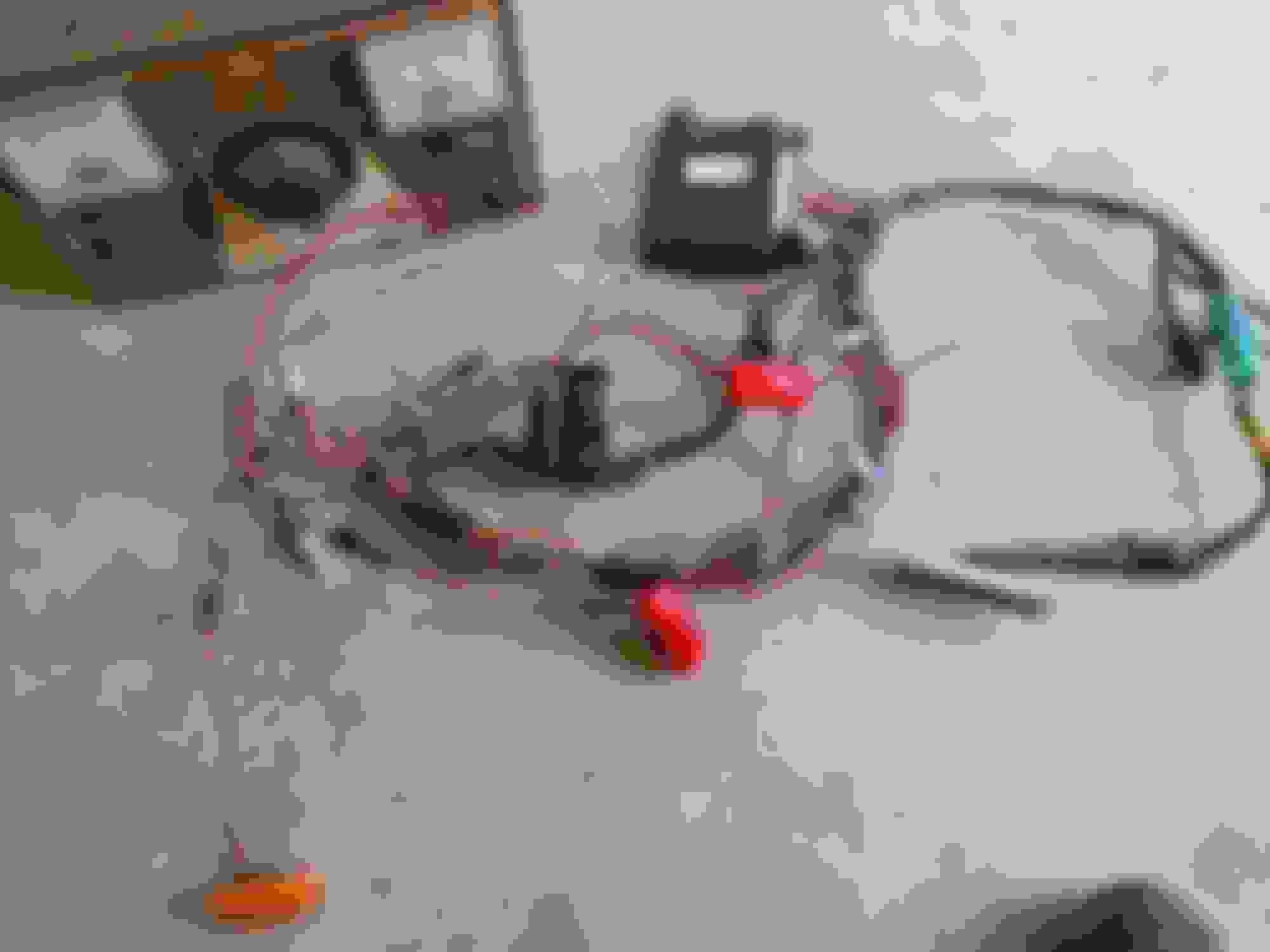
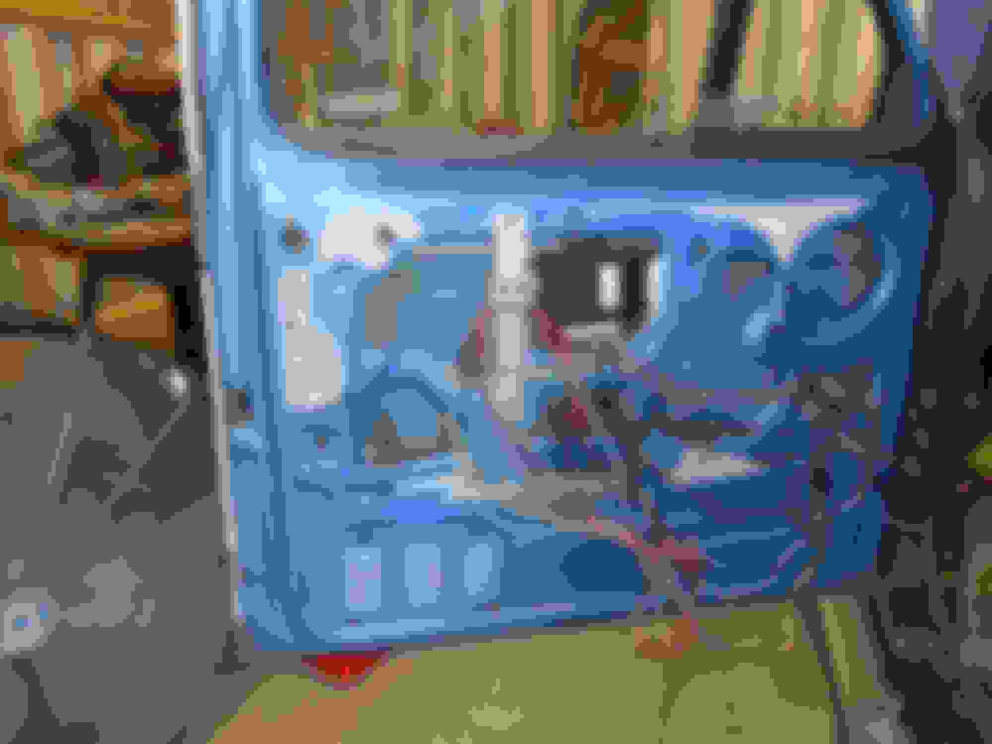
Here is a system and partial harness removed from a 1996 Lincoln Town Car:
It obviously has a bunch of extras, like memory seat etc. One of the issues I discovered in researching the systems, the truck RKE uses the lock switches to ground the module wires, the car system uses the switches normally, just lower current (10A vs 30A).
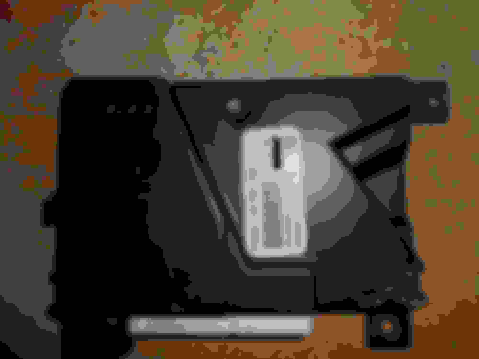
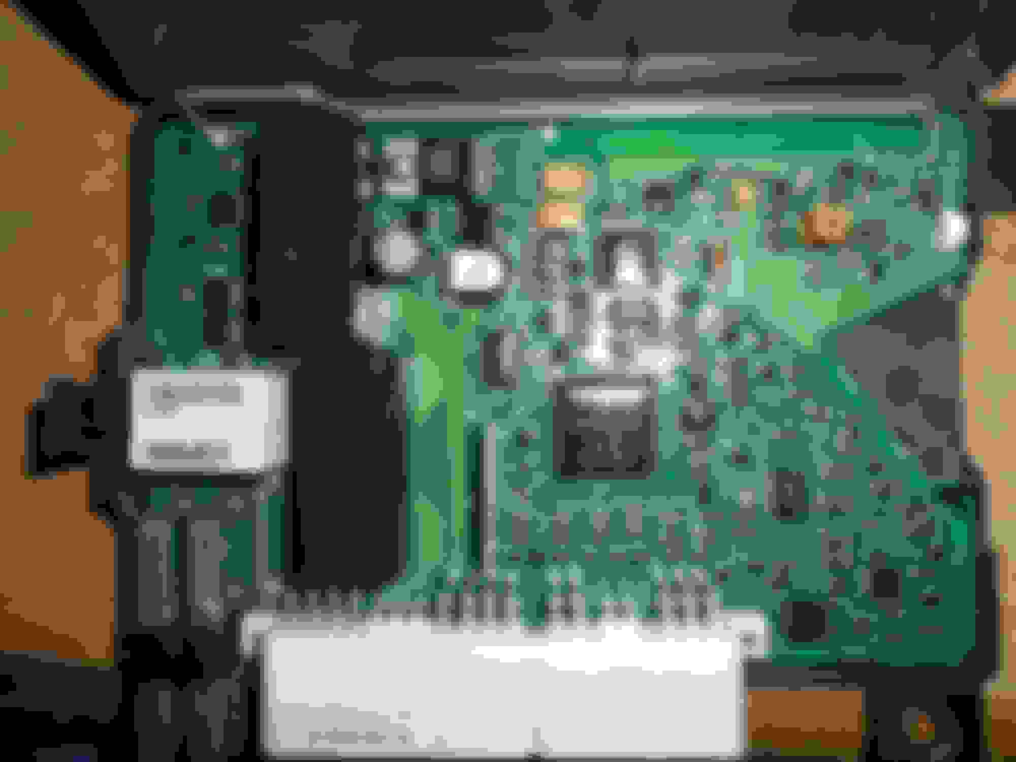
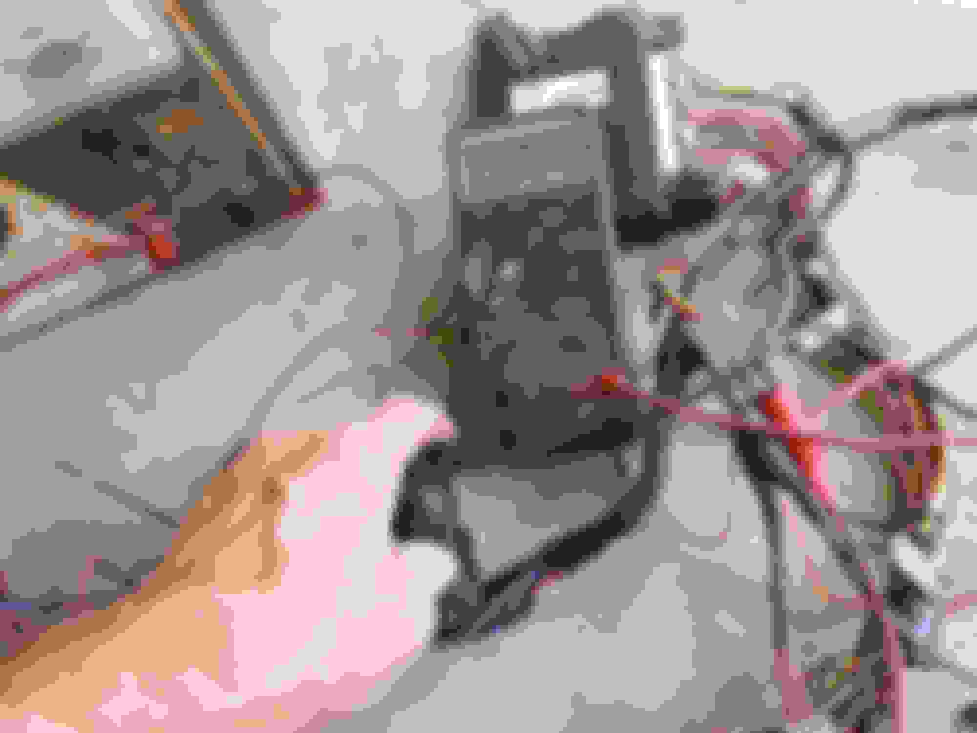
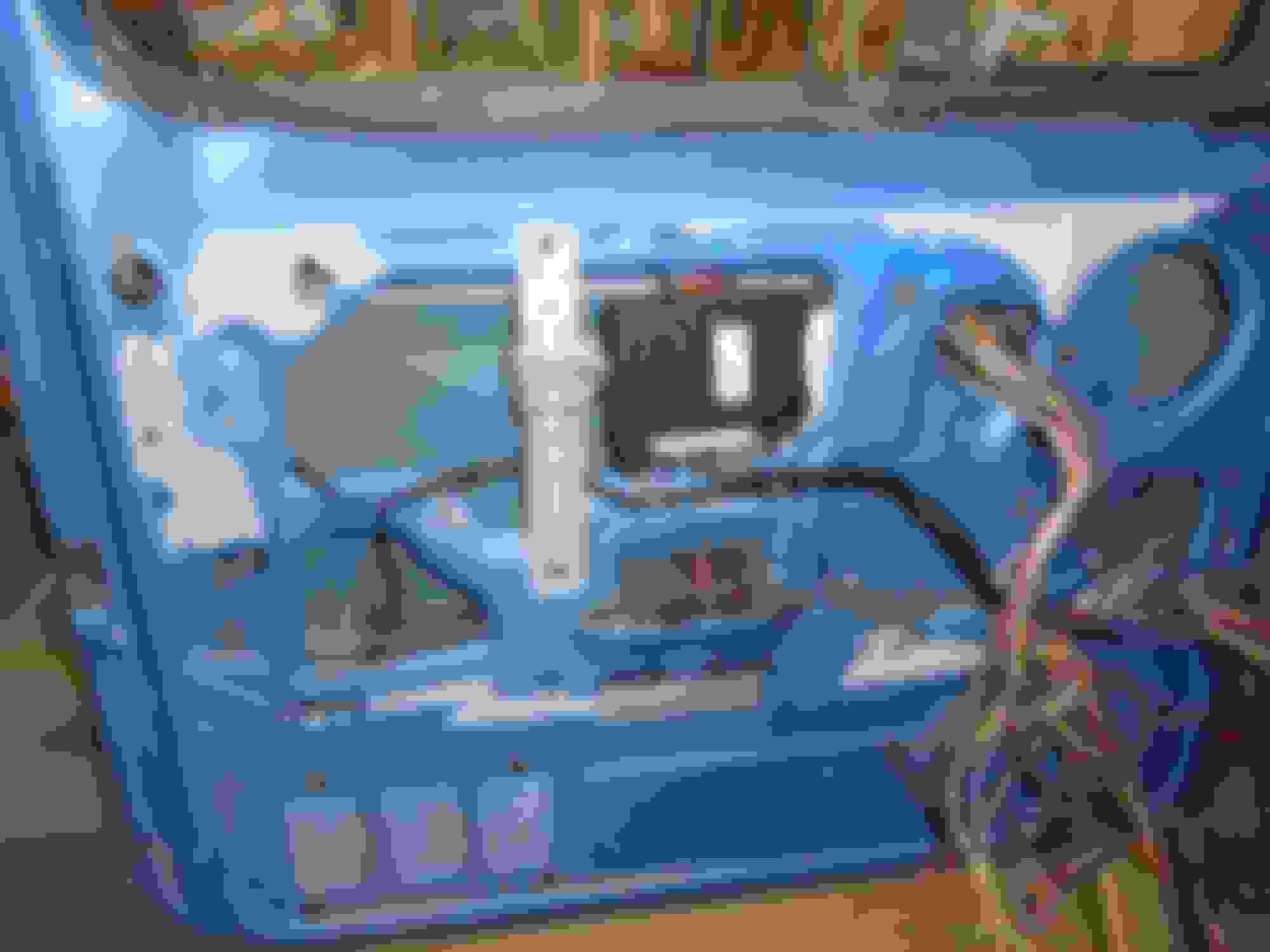
Here is the module, the large wire connector is power for the lock motors and the one touch down.
The two black relays are the locks, white relay is one touch down. Notice the heavy pins on that end. The antenna is the large sheet metal piece.
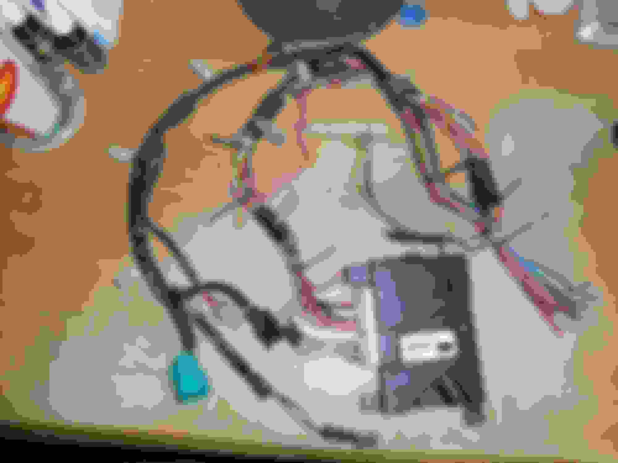
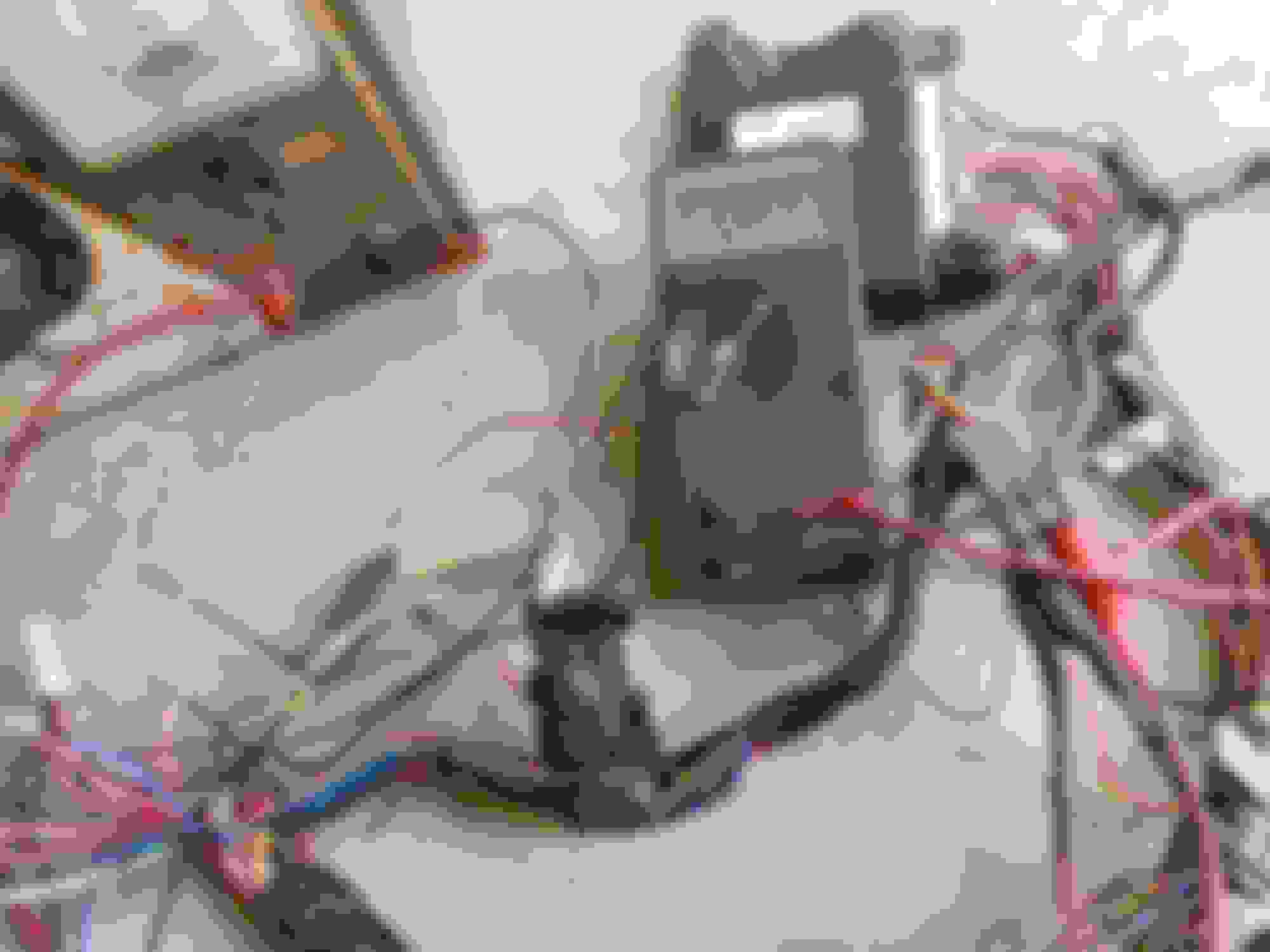
Here is the wiring and module with the power seat, memory switch plug and door panel switch plug removed along with stripping the window switch down to just the left front portions.
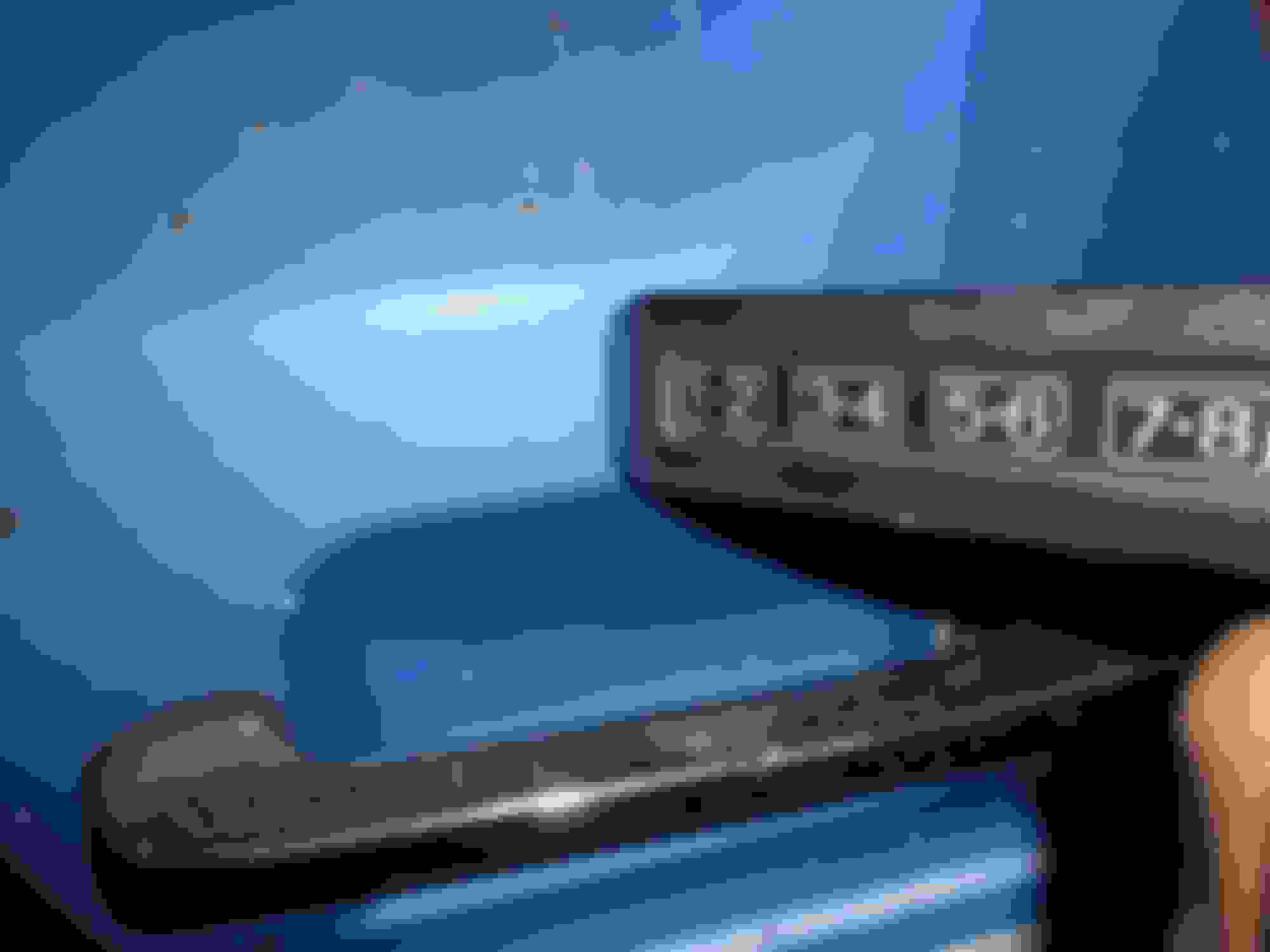
Here are two pictures of the key pad for location, it will fit on the flat area just above the door handle, and on the Town Car, the wiring passed behind the rear glass run.
The unit is located in the lower front of the driver's door and is called a left front door module.
I pulled the same system out of a 98 or 99 Merc Grand Marquis. Going to use it for opening and shutting the power door on my bus using the power locks feature. It will interface into a one shot timer to close and open the power door using relays for current draw of the door motor.
I hope that number which is blacked out is readable. That is the factory keypad code, with out that number it's a paper weight. Not sure of that number is needed for FOB programming (probably is needed). The car I pulled the modal from had both FOBS!
Check that keypad, the one I got was full of water and was rotted up dead and I had to go back and pull another keypad at the next jy run.
I blacked out the number because I don't feel like publicizing it. The key pad will be verified, right now I am getting the system ready so I can test it using my nice 12V regulated power supply. This one has a nice click to each of the numbers. BTW, the number is also on the trunk hinge, at least our 1990 was.
Snag a couple of one touch down modules, on a 95 or older Taurus they are clipped on the inside of the driver's door panel, I believe they run till the current spikes then open the relay. That is how the old rear window system on the suicide door Continental convertibles worked, except it was all relays. They had to lower the rear windows half way to avoid snagging the top on the sharp corner of the window frame. Once you closed the door, the window would go up to it's stop, the climb in current would dump the system and turn off the courtesy lights. Damn cars had a relay bank behind the rear seat and enough motors and pumps to give you a headache.
Last edited by 85lebaront2; 10-11-2015 at 08:34 PM.
Reason: Added info.
Today I hooked up the system for a bench test. Unfortunately, the lock/unlock pulse is fairly short and hard to get a picture of while working the keypad. I did get a few using the switch, even then it is a short pulse.
First picture is the setup, power supply is an old surplus USAF unit and is heavy!
I used some spare marker lamps as indicators, amber is lock, two red ones are driver's door unlock, other three unlock. This is lock activated.
The next one is "unlock all" by using the switch.
Now it was on to the window circuits, up is normal through the switch, I hooked up the meter so up was positive and down was negative.
Down using the switch, the module still turns the motor on with a relay, even when the switch is held in down.
Finally, the one touch down feature, notice the switch isn't depressed.
Before anyone asks, the wire nuts were just to hook things up for testing, everything will be soldered and heat shrink covered.
Now I will get into a mini Gary Lewis dissertation on how the power lock system works, how the factory truck RKE works and how the car RKE works and the differences.
First, Ford and most other American manufacturers use a neutral grounded system, specifically when the switches or control module is in neutral, or rest condition, all the output wires are connected to ground. On the lock system this means that the master switch (driver's door) has a pair of ground wires, the reason it has a pair will become evident shortly.
Power comes in to both lock switches through circuit #517, a black with white stripe wire. When the master switch is pushed to "unlock" power from this wire is connected to circuit #120, a pink with light green stripe wire, this wire connects to one of the two "ground" pins of the slave switch. This then powers circuit # 118, a pink with orange stripe wire. The circuit completes through the lock motors (2 or 4) back through circuit #117, a pink with black stripe wire, through the other end of the slave switch and out to circuit #119, a pink with yellow stripe wire, to the other end of the master switch where it connects to one of the ground wires.
On the truck RKE system, the same two circuits, 119 and 120 are used, but the two switches instead of having power fed to them have a ground to the center and ground the module wires to activate the locks.
RKE systems have another feature, an "unlock driver's door" and "unlock all other doors". As a result, the unlock has an extra circuit that only goes to the left front door, #163. a red with orange stripe wire.
On the car systems, the same circuit numbers follow, but, and this is a big one, the switches are fed power through a 10 A fuse through circuit #296, a white with purple wire, that also powers the key pad. The switches power circuit #119 to tell the module to lock and circuit #120 to tell the module to unlock. The switches do not have a ground connection.
In adapting one of these to a truck, obviously the ground wires have to go and the lock motor wires to the slave switch need to be removed and either cut off or taped to prevent shorting. The two wires from the master switch, circuits #119 and #120 need to be moved so the switch simply triggers the module. The left door or left front on a crew cab, has to have it's unlock lead circuit #118 cut and the wire connected to circuit#163 so the features will work properly.
Now I will get into a mini Gary Lewis dissertation on how the power lock system works, how the factory truck RKE works and how the car RKE works and the differences.
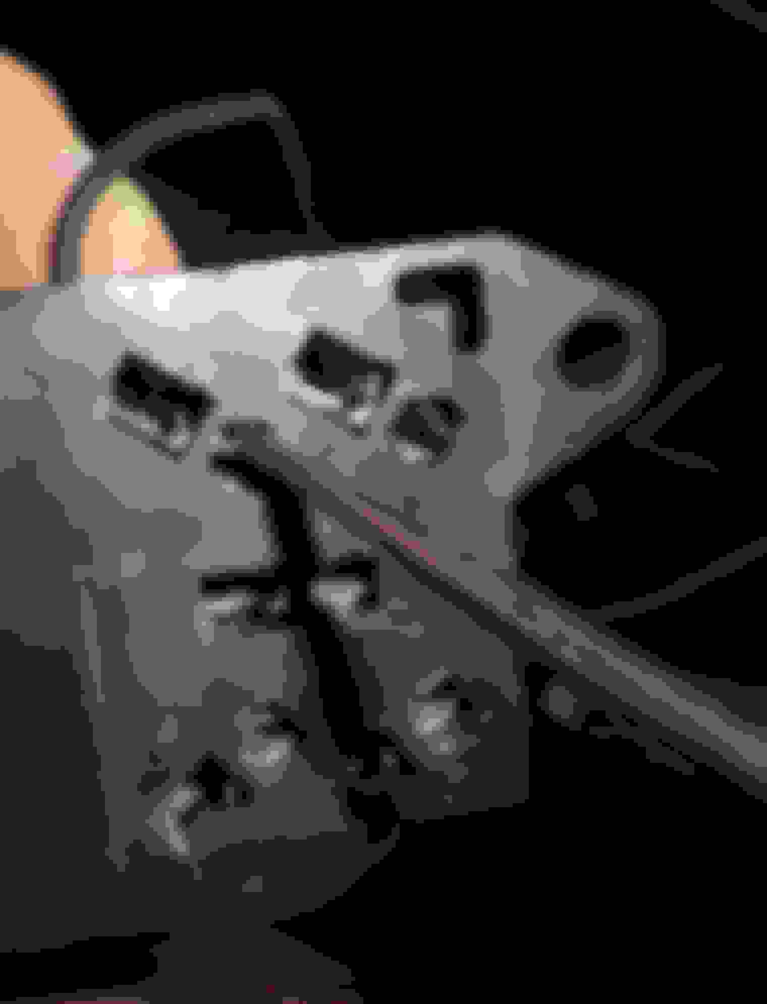
Now for a few pictures to hopefully make it a little clearer. The first is the two ground leads that have to be removed. The red arrows are the two black wires that need to come out so the slave switch will not short the power feed. Note the slots the wires are in, this where they are inserted at the factory.
The next picture is demonstrating how to remove the connectors from the switch sockets. There is a small tang visible in the slot that is being depressed with the pick. Once it is depressed the wire slides out of the slot by pulling it along the slot.
Now over to the right door to remove the pink and black and pink and orange wires and move the oink and light green and pink and yellow wires to where the others were.
Here I have untaped the door harness back to the splice location so the extra wires can be cut off and the harness re-taped.
Now it was back to the left side for the real fun! First finding a suitable location for the module and making a mount for it. On the big sedans, it sits in the lower front of the left door and the window motor sits behind it so the original harness sort of looped down to the module and back and over to the lock motor, door latch and key pad wiring. Before the wiring can be completely routed, the key pad had to be installed so it's 8 pin plug can be connected by running it behind the window channel.
Once I have the lock motor and key pad wiring locations established, I will be able to determine which wires need to be lengthened and which shortened.
Got some more of the wiring done today, got a late start because the Keurig decided it needed descaling. I got the key pad mounted permanently with it's retainer clip. I need to finish cleaning it now, the gasket was damaged when I removed it, so I put a thin bead of RTV around the back of the flange, let it partially cure, then installed it.
The cable for it runs around behind the glass run, but high enough the clear the door latch linkage. The next portion was mating the existing 1996 door wiring with the piece from the Lincoln. Some of it was fairly easy, Ford is pretty good about sticking with a color code for a particular function, so most of it involved matching the wires and making sure they are long enough to reach. I am modifying the power window and lock harness. If any of you have had to work on one of them, there are two basic styles, the earlier one used up through 1991 which has connectors at each end of the harness where the doors connect and the later style used from 1992 on, where the only connector on the harness is at the right cowl. The left door harness essentially goes all the way across the cowl, just below the windshield. It can be seen running from left to right through the white clips. Needless to say, I wasn't planning on removing the dash in order to work on this harness. I cut it in the left cowl area and am installing a connector there.
This is how the door wiring looks currently, hopefully I can finish it tomorrow.
 10-11-2015, 04:47 PM