When you click on links to various merchants on this site and make a purchase, this can result in this site earning a commission. Affiliate programs and affiliations include, but are not limited to, the eBay Partner Network.
So all you have to really do is remove the Amp Meter and install the Volt Meter into the instrument cluster. The original Amp Meter wiring has hot power on both terminals and thus will not work at this point. A Volt meter needs power and ground. I choose to use the truck's original wiring to do this instead of altering or modifying the circuit film on the back of the instrument cluster.
The original amp meter wiring is located near the battery. The minimum wiring changes needed are cutting and grounding one wire under the hood as shown in the attached photos. The wire you cut is the SMALL yellow wire not the big yellow one. Strip the firewall side of the small yellow wire (cap the other end) and jumper to ground. That's it. Now check out your new Volt Meter; i'ts reading Battery Voltage.
Well you might have noticed that you never turned ON the key switch. The original Amp Meter wiring was Hot all the time, powered off a fusible link. The new Volt Meter draws 68mA (.068 amps) of parasitic battery drain. While that might be OK for a new car these day, I don't think it's a good idea for trucks that are not driven frequently, so if you agree go on to Step 2.
Step 2
Find the small red wire that is right next to the small yellow one you just cut. The red wire is supplying the Hot Power to the volt meter. You will need to cut the red wire and feed Switched Key ON power into the Firewall side of the red wire. Be sure to cap engine side of these wires as they are hot all the time. For my KEY ON power I used an extra power wire I had left over from my DS2 conversion.
So now to recap...
The firewall side of the small red wire is now the positive feed point for the new voltmeter and firewall side of the small yellow one is now the voltmeter ground. Be sure to cap off the engine side of these wires you cut as there is still hot power there.
Reasons to do the swap:
The Amp Meter needle deflection is so small that it is nearly impossible to tell when the Alternator has failed, even at night with the lights on you will only see about a needle's width of movement toward the discharge side.
3G Alternator swap. The Amp Meter no longer works due to bypassing the Shunt Wire with larger gauge wire.
Safety stuff...
Removing the Battery Negative terminal while doing wiring on your truck will prevent bad things from happening.
While on the safety topic, it would also be a good idea to buy an inline fuse holder with a one amp fuse installed in it and use this as the jumper wire to ground, or in the power supply side. Point being that if anyone else at a later time did reinstall a stock instrument cluster with an amp meter, the fuse would protect the wiring and amp meter from smoking. The original amp meter wiring was not fused or protected.
This “How To” is a work in progress. Please feel free to add info and/or links with additional info, like how to R and R the instrument cluster or what source you used for Key ON power.
The following posts will have the photos with captions for a step by step installation.
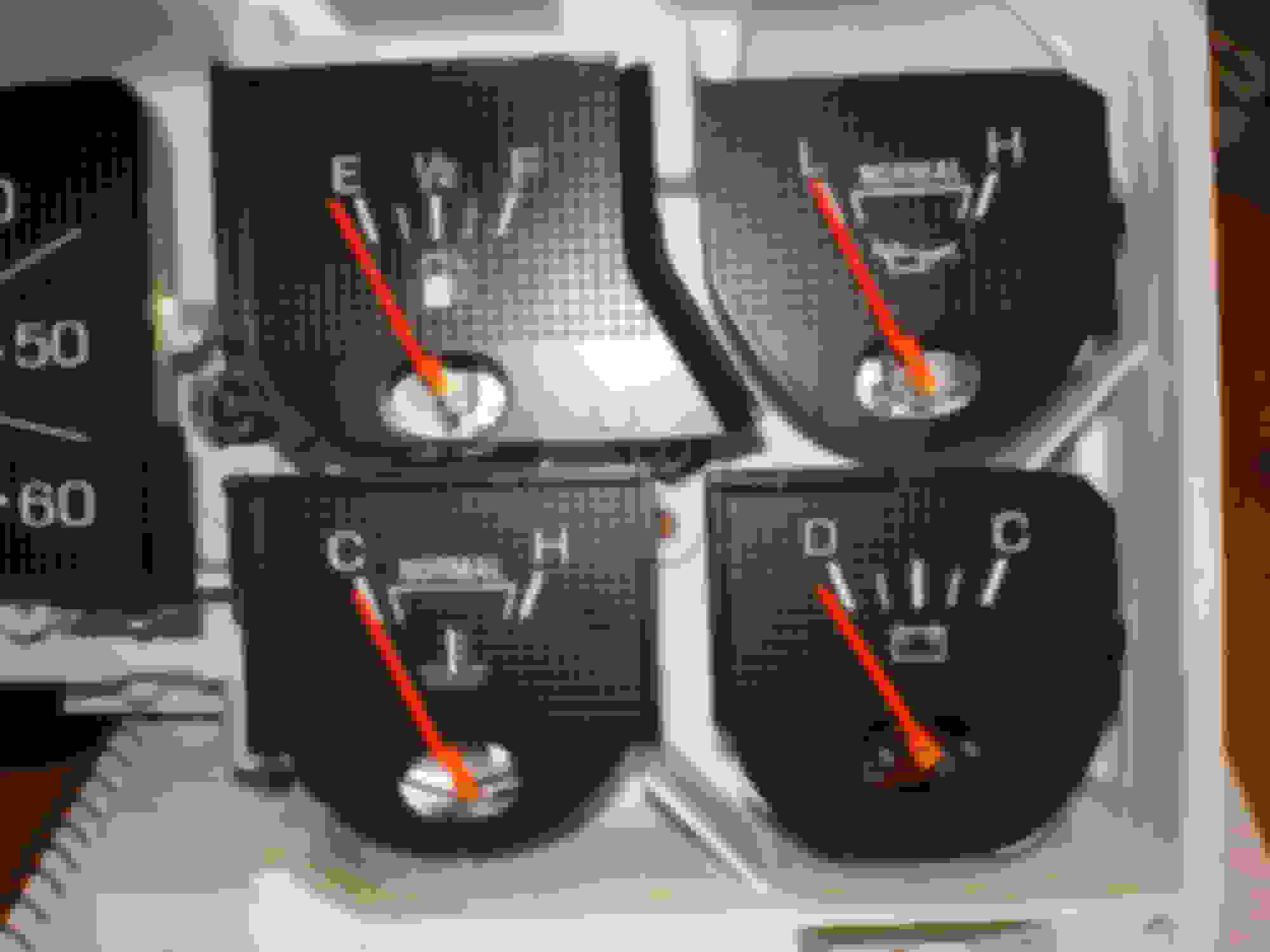
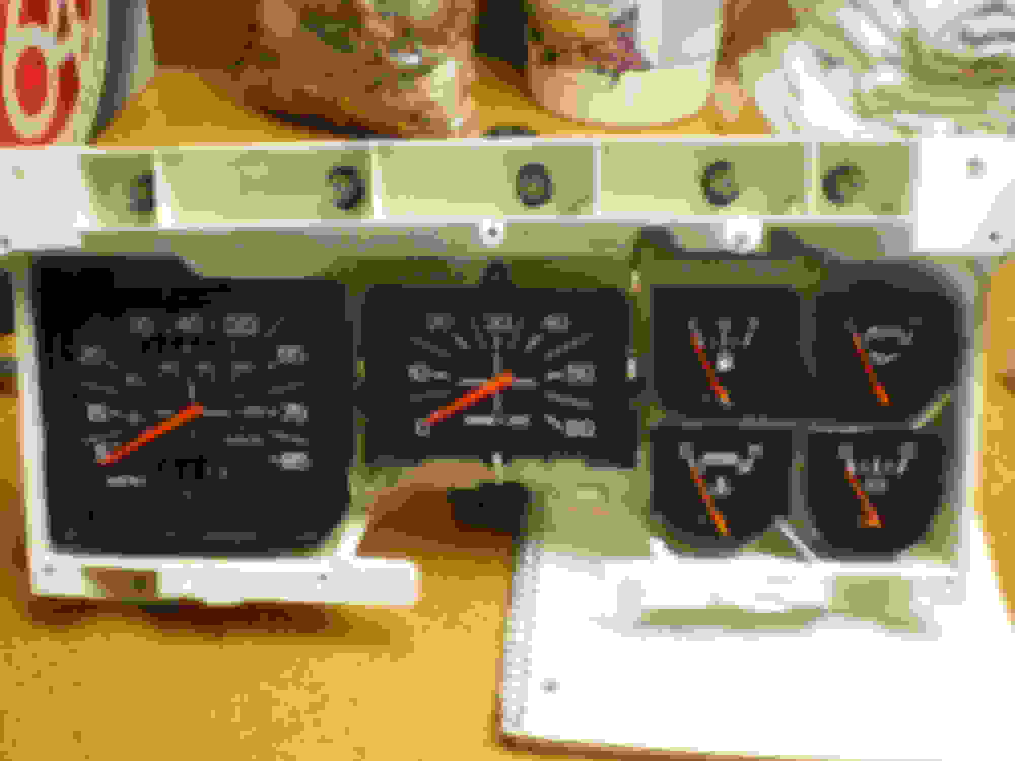
Here are some photos of the new voltmeter. You should repaint all the needles to match the new voltmeter
.
Bob can provide the paint for the needles which will save on shipping cost.
I use HP-FLRED pointer paint from HiPo Parts for the factory look.
or
Testors Model Master Fluorescent Red FS28915 for the 'aged' look.
Both come in small bottles
Here is some info on bench checking the voltmeter before I installed. My trucks 3G ALT runs about 14.5 volts give or take a little, depending on if the lights are on. The stock 2G was a lot lower voltage.
.
I think I introduced Gary Lewis to the Rocketman site.
He has documented the results of his conversion.
I have a stock voltmeter in my '87 and found that putting the headlight relay harness and a blower relay in, resulted in much more stable cab (dash) voltages.
What's the ground path?
I have two new cab seam to frame ground straps and a good cable from the wiper motor to the back of my intake.
My 3G setpoint is 14.35V.
I see that at the battery but not in the cab.
Most of the load is off so shouldn't the voltage throughout the truck be the same?
The Voltmeter is grounded to one of the bolts on the starter solenoid.
The voltage should be reasonably stable and consistent until you add load. I also have headlight relays. I notice my biggest fluctuations on the new voltmeter when I turn my fan on high as my voltage is being read off the fuse block somewhere.
The set point for the voltage regulator is based on where the yellow wire is connected to.
Most just jumper this wire to the main ALT output stud on a 3G swap. So in a sense, the ALT is it own reference point. Ford ran the yellow wire to the far side of the ALT shunt wire. This slight amount of resistance in the shunt wire coupled with the dampening effects of being closer to the battery helps create a much more stable reference point.
Attached is a photo showing a schematic for a stock Amp meter and where the yellow wire is connected to. Also there is a drawing of the stock amp meter current divider with resistance values.
Jim
.
3G regualtors are available in various set points.
I happen to have a white LRC regulator set for 14.35V.
The cabling and such provides no drop to the relay and battery.
I don't see anything grounded at the relay mounting screws.
The cab is well grounded (I think...)
Just not sure if my voltage drop is in the ignitin switch, fuse panel or the cluster itself.
Good write-up, I don't know if linking to OB violates FTE's policies, but I actually did a write up on this as well last year over there. I have some pictures of the actual swapping of gauge guts into the old housing.
Good write-up, I don't know if linking to OB violates FTE's policies, but I actually did a write up on this as well last year over there. I have some pictures of the actual swapping of gauge guts into the old housing.
Attempted to wire my ammeter like described and when I hit the key the gauge went all the way to the left and then popped back to center and the gauge started smoking. What did I do wrong? Yellow to ground and the red to a keyed 12v.
Attempted to wire my ammeter like described and when I hit the key the gauge went all the way to the left and then popped back to center and the gauge started smoking. What did I do wrong? Yellow to ground and the red to a keyed 12v.
The first sentence in post 1 is....... You can buy the Volt Meter from �Rocketman's Classic Cougar Innovations� for $45
Did you do this?
 10-06-2014, 01:24 PM