When you click on links to various merchants on this site and make a purchase, this can result in this site earning a commission. Affiliate programs and affiliations include, but are not limited to, the eBay Partner Network.
I purchased an F250 with a 1975 title that was claimed to have a 1978 body on it. It isn't a highboy though and the wiring doesn't seem to correspond with the normal 1978 wiring either. Any help is appreciated.
The ignition didn't work. They added a push button switch which is also not currently connected to anything. This truck has a 3G alternator upgrade but the already regulated alternator was wired through the regulator. It wasn't charging properly and was also running the battery down with the truck off.
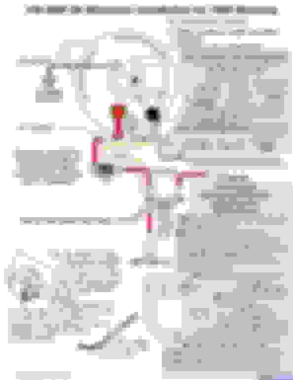
So starting at the alternator plug I see the first issue. According to the wiring diagram I goes to ignition, A would go to the same terminal on the solenoid as the main alternator output, and S goes to it's own little plug on the alternator. So I think that is all figured out.
What is confusing is what the rest of this is. Both I and A were connected together to a skinny orange wire. It is about 3 ft long.....
That orange wire is then connected to a skinny yellow wire that is another 3ft long.....
Which finally makes it's way to this little rubber block. It appears to pass through and connect to the red wire going up into the plug.
There are 2 thicker black wires in that rubber block also. One is short with a ring and red tape around it and went to the solenoid. The other is longer and just bare on the end which went to the positive on the battery. Again, both of these wires are black so it is confusing.
This is the other end of the connector that it plugs into. The red wire is the one that was coming direct from the alternator I and A before. The yellow goes to nothing, it is broken off. There is also the larger wire that appears to be black/yellow stripe but is purple/green stripe on the other end of the plug. This looks to have a connector that would go to the solenoid or main pin on the alternator.
I will be honest that I am lost on this. This is the rest of the wiring from above that plug where nothing seems to go to anything. The only one I was able to see and label is the I that goes to the solenoid. There are two additional black wires that apparently come from the push button to start it. I'm not sure where those need to go either.
Is there a simple drawing of where this all goes? Because of the 3g alternator, the switch, and no knowing what year it is i don't quite know where to start. something needs to get power to the ignition and power to the dash, etc.
Tired of messing with it?
In case you want to replace the alternator wiring harness, that's the one that goes from the alternator to the regulator.
Harness, alternator wiring
Fits 78 f100-350 w/ amp and oil press. gauges all engines and 70 amp Ford alternator
D8TZ-14305-B
Green Sales, Cincinnati, OH has 40 (800) 543-4959
Also...Ignition modules, 74 (black grommet) and 75 (green grommet) are year specific and will not interchange.
76 to 79 (blue grommet) are interchangeable.
Ignition modules: 1974 is 1974 ONLY / 1975 is 1975 ONLY.
Blue module introduced in 1976 was used well into the 1990's.
1973-1974 ?? D4AZ-12A199-C
Green Sales in OH. has (34)
Collectors Auto Supply in WA. has (1)
Haven Ford in KS. has (2)
Klimesh Motor Sales in IA. has (2)
Bob Allen Ford in KS. has (3)
Freese Motor Inc in IA. has (1)
Wesley Obsolete Parts in KY. has (1)
Dennis Carpenter Ford in NC. has (2)
Lost of threads on the 3 G swap, use the advanced search option.
I think you'll be time (and frustration) ahead by scrapping that butchered harness and rewiring the alternator to match the diagram.
As for the pushbutton start switch. If you don't want to repair the wiring to use the key switch, one wire from the pushbutton needs to go to a constant 12 volt hot and the other wire needs to go to the small "S" terminal on the starter solenoid.
I peeled back the electrical tape a little so I could get a better indication of color after looking at the line drawings. Here is what I have determined but still don't know where a few things go and just want confirmation on the rest.
These are the 2 wires coming out further up in the harness. The brown was marked "I" before. The Red/blue looks like it should be going to the "S" terminal on the solenoid. Is that correct? This red/blue was not connected to anything before which would explain why the ignition didn't work and they needed the button to start it.
There is a 3 wire plug. Black/yellow looks to be the main power to the ignition and should be hooked direct to the battery or the B+ side on the solenoid. What about the other 2 wires though? I see a yellow going to B+ side of the solenoid for the horn relay. Wondering if that is what this yellow is. I am less sure on the red wire. The yellow was going to nothing before and the red was going to both the A and I terminals connected together on the alternator which is obviously not correct.
Then there is a 2 wire plug. According to the line drawing the red/grn wire goes to ignition. It looks to connect to both the "I" terminal on the alternator and "I" terminal on the solenoid as it connects to the brown wire as well. If that is the case I should be able to bring this red/grn wire, the brown wire, and the green/red wire from the alternator all together at the "I" terminal of the solenoid. Is this correct?
The green/yellow I am unsure of. This plug was not hooked up to anything before so neither of these wires was used.
Then there are 2 other wires individually. One is a yellow wire with a tiny greenish line on it. This was hooked to the B+ before. What does this one do?
Finally is the white wire with thin black stripe with a fusible link. There is a small ring terminal on it so it looks like it was connected at the solenoid before. The only thing I see that is white/black is going to backup/washer fuse of 15amp.
The alternator itself was simple to install and wire. I ended up running 1/0 from the alternator to a 150a ANL fuse and to the B+ terminal. I then ran 1/0 to the second battery which was installed because the plow and lights are fairly demanding on the electrical system. 1/0 is run to the starter, body ground, and to the engine ground as well.
I think you'll be time (and frustration) ahead by scrapping that butchered harness and rewiring the alternator to match the diagram.
As for the pushbutton start switch. If you don't want to repair the wiring to use the key switch, one wire from the pushbutton needs to go to a constant 12 volt hot and the other wire needs to go to the small "S" terminal on the starter solenoid.
Ok, i think that is how they had it before. Issue with that is you could crank the starter without the key even it but it couldn't run. I'm thinking the one end of the button should come from the ignition rather than constant power so the key has to be turned to the run position to crank the starter.
If your truck has a horn relay, that precludes this being a '78 harness, unless your truck has cruise control.
73-77 trucks used a horn relay that had three wires. Yellow was constant hot, lt blue w yellow trace was to horn switch, yellow w/ green trace was hot to horn(s). In '78 the wiring was changed. Only trucks equipped with cruise control still used a horn relay. Trucks without cruise had twelve volts to the horn(s) through the horn pad on the steering wheel.
It would help to know what harness you're dealing with. If you're lucky the main harness will still have the ID number tag on it. It's behind the speedometer. A small (usually red) label wrapped around the harness.
That chopped up wiring looks like mine did in my 73 when i got it. The rubber connections look like my 73s . My 79 had plastic connections like those in post #7 . I don't believe you have a 78 cab , probably a 75 .__JIM

 07-26-2014, 10:08 PM