
Rebuilding a Double Cardan Joint (Vid/Pics)
#1
 07-09-2011, 10:56 PM

Join Date: Dec 2009
Location: Fort Campbell, KY
Posts: 864
Likes: 0
Received 0 Likes
on
0 Posts
Rebuilding a Double Cardan Joint (Vid/Pics)
How to rebuild the Double Cardan joint found on 137” to 142” wheelbase SD F250's.
Parts needed:
Double cardan joint repair kit (Neapco, 77-0081 NG) Qty-1
Joint replacement U-joints (Spicer, 5-1350X) Qty-2
Rear pinion U-joint (Spicer, 5-1410X) Qty-1
High quality grease (for the slip joint)
Clamps (for the slip joint if you have to cut the old ones off, Zip ties can work)
Lock tight (for U-joint straps at the pinion)
Anti-Seize (for the U-joint caps)
Tools needed:
8mm socket (pinion U-joint straps)
12mm, 12point socket (champion flange at the transfer case)
Needle nose pliers
Flat blade screw driver (1-large, 1-small)
Channel locks
1” Deep well, 1/2” drive socket
Press, conventional hydraulic or C-press (screw type), if you do not have either...
21mm 1/2” drive socket (to drive the U-joint caps in and out)
4lb mallet
Hard flat surface to do the driving
Something to mark on the driveshaft (grease pencil, paint pen, zizwheel, white fingernail polish)
Parts washer, or other cleaning solution
A creeper is a huge plus, you shouldn't have to jack up the truck.
[If you want to add the Zerk fitting]
You'll need a small fitting
7/16 drill bit
90 degree grease fitting for the Zerk
When do you rebuild/how do you know it's time? Well for me, I knew there was close to a quarter million miles on the centering ball, and the U-joints have only been replaced once. That was enough for me. Most people for some reason neglect this joint.
Removal:
Take your marking tool and mark the orientation of the driveshaft at every removable point. So you should have a mark on the pinion, tail section of the slip yolk, driveshaft at the slip yolk, up front you should have a mark on the driveshaft, the center section of the double cardan joint, the spider trunnion attached to the center section, and the output champion flange from the transfer case. Mark it well enough so you can put it all back together exactly like you took it apart.
Loosen the 4 bolts at the transfer case using a 12mm, 12 point socket. Remove 3 of the bolts, leaving one installed loosely so you can access it with one hand.
Use your 8mm socket to loosen and remove the U-joint straps bolted to the pinion. Then remove the rear of the driveshaft from the pinion, reach toward the transfer case and remove the remaining bolt. You should be holding your driveshaft now, completely free from the truck.
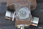
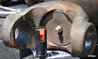
If your double cardan joint does this, it's probably time to rebuild!
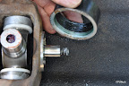
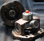
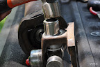
You need the needle nose pliers, channel locks, and a flat blade screw driver. Start with the center section of the joint. I did most of the work on my tailgate. Remove the keepers, and drive the old U-joints to one side, once the caps are extended past the center section, take the channel locks and remove the caps. (If you caps are stubborn, try some vise-grips and soak the cap with PB Blaster)


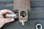
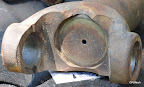
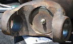
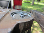
Once you disassemble the joint you'll have the driveshaft, center section, and the front spider trunnion. The front spider trunnion houses the centering ball, along with its seal, and the drive shaft has the small shaft that engages the centering ball, a spring, and the outer dust shield for the centering ball.
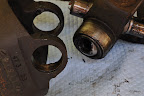
The centering ball is pressed in the front spider trunnion, but not very tight. There is a tiny seal pressed around the centering ball, it pops right off with the screw driver. Then the centering ball can be removed with the same screw driver and 21mm socket. You may have to give it a couple good “prys” in order to unseat the centering ball.
Finish removing the U-joint from the driveshaft and from the spider trunnion, and your finished with disassembly. Now clean everything up, and get ready to reinstall.

Installation
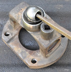
Start with installing the centering ball in the spider trunnion, use the 1” Deep well socket to drive it in. I greased the spider's cavity well with caliper grease to help dispel water, and assist in the prevention of other contaminants from entering the centering ball's cavity. There is a small hole in the spider trunnion at the rear of the centering ball cavity, perhaps to allow moisture to exit. After driving the centering ball in with the socket, you will need to use the flat blade screw driver and tap it around the edges to completely seat it. (unless you have a THIN walled socket) Now install the new seal around the centering ball using the same socket. Your done with this part, leave that cap in the centering ball. (but take the spring out of the inside of it, it goes in the driveshaft end.)


Next install the dust shield on the driveshaft. Be careful not to damage it. I lubed it up good with caliper grease after it was cleaned, so it went on pretty easy. Use the flat blade screw driver with a small hammer to completely seat the dust shield on the driveshaft. Install the spring into the end of the driveshaft.
Now install the first U-joint in the driveshaft and center section. Use the 21mm socket (or press), coat the caps with anti-seize so in the future they will come back out. Just ensure you do not get the anti-seize into the needle bearing grease or the cap. **Make sure you line up your marks!**

The Spicer U-joints ship with 3 different sized keepers, while they all would fit, the ugly green ones where the best.

Last U-joint will be installed in the spider trunnion first, then into the center section. **Make sure you line up your marks!**
Make sure the keepers are completely seated.

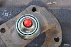
Now the fun... installing the spider trunnion into the center section. Make sure the driveshaft is stationary (not easily rolling around), and that you can articulate the joint. You'll have to cant the joint in one direction, and shift the U-join in the spider. You'll have to remove the shipping cap (red in my case) from the centering ball, and this exposes the needle bearings, they're smaller than U-join bearings, and a pain in the A$$, so take your time lining everything up. As you assemble, you'll see that the spring in the driveshaft is in your way, and will be what knocks your needle bearings out. Take the flat blade screw driver and compress the spring enough to clear the centering ball and pay attention to the U-joint insertion. Both need to happen at the same time, it will if your angle is right. Once you clear the spring and your U-joint is landing in the hole, push it in straight as far as you can, then actuate the joint a small amount to ensure your all the way in the centering ball with the driveshaft. You'll know if some of the needle bearings fell out when you articulate the joint. No biggy if they did, you'll just have to R&R the spider and reset all the bearings. (don't ask me how I know) You don't want to force it because you might damage one of the bearings.

I couldn't get a shot of the exact positioning, because I'd need 3 arms and an editor for the language It's not that hard though. That's it for the double cardan.
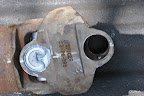
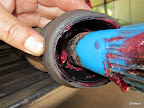
The slip yolk end is straight forward, and you can see I added a Zerk fitting for the addition of grease without having to remove the driveshaft.
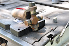
Hole for the Zerk


Couple of notes:
Your keepers should be extended a little in the center, indicating that the U-joint is “squeezed” a small amount in the yolk.
Your U-joints should be quiet tight. When installing the keepers on the opposite sides, if your having trouble getting them seated, check how easily the joint pivots. If it's easy, the cap isn't pushed in enough. If it is tight, ensure you cleaned the grove well so the keeper can ride there. Prior to installing the slip yolk, I greased her up WELL. The manual calls for adding grease to the boot also.

Last but not least, reinstall the driveshaft. Hopefully you lined everything back up the way it was removed. Put all your bolts and tools close to where you're working, have the lock tight already on the 8mm bolts. Install one rear strap on the pinion (closest to the bottom) loosely so you can slip the U-joint in there and have it stay, then move toward the transfer case and install the 12mm bolts. Then put the other strap on the rear. When all the bolts are in, torque the pinion to 26ft/lbs (8mm), and the transfer case to 76ft/lbs (12mm).
End result...
Very pleased with the out come. You really have to crank on this thing now to get it to move.
So a road test confirmed that this joint was in dyer need of maintenance. Smoother, no vibration, less backlash, etc. There's plenty more pictures in the album, I just hate how Google only lets you put the pictures in a single vertical row, and 30pics are the limit on this site.
__________________________________________________ ___________________________________________
@CPUNeck Do you have larger image files? This thread has been added to the 7.3L Tech Folder, but the images are rather tiny. Please PM Y2KW57 if you have access to slightly larger (800x600) image files. Thanks! (And nice write up!)
Parts needed:
Double cardan joint repair kit (Neapco, 77-0081 NG) Qty-1
Joint replacement U-joints (Spicer, 5-1350X) Qty-2
Rear pinion U-joint (Spicer, 5-1410X) Qty-1
High quality grease (for the slip joint)
Clamps (for the slip joint if you have to cut the old ones off, Zip ties can work)
Lock tight (for U-joint straps at the pinion)
Anti-Seize (for the U-joint caps)
Tools needed:
8mm socket (pinion U-joint straps)
12mm, 12point socket (champion flange at the transfer case)
Needle nose pliers
Flat blade screw driver (1-large, 1-small)
Channel locks
1” Deep well, 1/2” drive socket
Press, conventional hydraulic or C-press (screw type), if you do not have either...
21mm 1/2” drive socket (to drive the U-joint caps in and out)
4lb mallet
Hard flat surface to do the driving
Something to mark on the driveshaft (grease pencil, paint pen, zizwheel, white fingernail polish)
Parts washer, or other cleaning solution
A creeper is a huge plus, you shouldn't have to jack up the truck.
[If you want to add the Zerk fitting]
You'll need a small fitting
7/16 drill bit
90 degree grease fitting for the Zerk
When do you rebuild/how do you know it's time? Well for me, I knew there was close to a quarter million miles on the centering ball, and the U-joints have only been replaced once. That was enough for me. Most people for some reason neglect this joint.
Removal:
Take your marking tool and mark the orientation of the driveshaft at every removable point. So you should have a mark on the pinion, tail section of the slip yolk, driveshaft at the slip yolk, up front you should have a mark on the driveshaft, the center section of the double cardan joint, the spider trunnion attached to the center section, and the output champion flange from the transfer case. Mark it well enough so you can put it all back together exactly like you took it apart.
Loosen the 4 bolts at the transfer case using a 12mm, 12 point socket. Remove 3 of the bolts, leaving one installed loosely so you can access it with one hand.
Use your 8mm socket to loosen and remove the U-joint straps bolted to the pinion. Then remove the rear of the driveshaft from the pinion, reach toward the transfer case and remove the remaining bolt. You should be holding your driveshaft now, completely free from the truck.
If your double cardan joint does this, it's probably time to rebuild!
You need the needle nose pliers, channel locks, and a flat blade screw driver. Start with the center section of the joint. I did most of the work on my tailgate. Remove the keepers, and drive the old U-joints to one side, once the caps are extended past the center section, take the channel locks and remove the caps. (If you caps are stubborn, try some vise-grips and soak the cap with PB Blaster)
Once you disassemble the joint you'll have the driveshaft, center section, and the front spider trunnion. The front spider trunnion houses the centering ball, along with its seal, and the drive shaft has the small shaft that engages the centering ball, a spring, and the outer dust shield for the centering ball.
The centering ball is pressed in the front spider trunnion, but not very tight. There is a tiny seal pressed around the centering ball, it pops right off with the screw driver. Then the centering ball can be removed with the same screw driver and 21mm socket. You may have to give it a couple good “prys” in order to unseat the centering ball.
Finish removing the U-joint from the driveshaft and from the spider trunnion, and your finished with disassembly. Now clean everything up, and get ready to reinstall.
Installation
Start with installing the centering ball in the spider trunnion, use the 1” Deep well socket to drive it in. I greased the spider's cavity well with caliper grease to help dispel water, and assist in the prevention of other contaminants from entering the centering ball's cavity. There is a small hole in the spider trunnion at the rear of the centering ball cavity, perhaps to allow moisture to exit. After driving the centering ball in with the socket, you will need to use the flat blade screw driver and tap it around the edges to completely seat it. (unless you have a THIN walled socket) Now install the new seal around the centering ball using the same socket. Your done with this part, leave that cap in the centering ball. (but take the spring out of the inside of it, it goes in the driveshaft end.)
Next install the dust shield on the driveshaft. Be careful not to damage it. I lubed it up good with caliper grease after it was cleaned, so it went on pretty easy. Use the flat blade screw driver with a small hammer to completely seat the dust shield on the driveshaft. Install the spring into the end of the driveshaft.
Now install the first U-joint in the driveshaft and center section. Use the 21mm socket (or press), coat the caps with anti-seize so in the future they will come back out. Just ensure you do not get the anti-seize into the needle bearing grease or the cap. **Make sure you line up your marks!**
The Spicer U-joints ship with 3 different sized keepers, while they all would fit, the ugly green ones where the best.
Last U-joint will be installed in the spider trunnion first, then into the center section. **Make sure you line up your marks!**
Make sure the keepers are completely seated.
Now the fun... installing the spider trunnion into the center section. Make sure the driveshaft is stationary (not easily rolling around), and that you can articulate the joint. You'll have to cant the joint in one direction, and shift the U-join in the spider. You'll have to remove the shipping cap (red in my case) from the centering ball, and this exposes the needle bearings, they're smaller than U-join bearings, and a pain in the A$$, so take your time lining everything up. As you assemble, you'll see that the spring in the driveshaft is in your way, and will be what knocks your needle bearings out. Take the flat blade screw driver and compress the spring enough to clear the centering ball and pay attention to the U-joint insertion. Both need to happen at the same time, it will if your angle is right. Once you clear the spring and your U-joint is landing in the hole, push it in straight as far as you can, then actuate the joint a small amount to ensure your all the way in the centering ball with the driveshaft. You'll know if some of the needle bearings fell out when you articulate the joint. No biggy if they did, you'll just have to R&R the spider and reset all the bearings. (don't ask me how I know) You don't want to force it because you might damage one of the bearings.
I couldn't get a shot of the exact positioning, because I'd need 3 arms and an editor for the language
It's not that hard though. That's it for the double cardan.The slip yolk end is straight forward, and you can see I added a Zerk fitting for the addition of grease without having to remove the driveshaft.
Hole for the Zerk
Couple of notes:
Your keepers should be extended a little in the center, indicating that the U-joint is “squeezed” a small amount in the yolk.
Your U-joints should be quiet tight. When installing the keepers on the opposite sides, if your having trouble getting them seated, check how easily the joint pivots. If it's easy, the cap isn't pushed in enough. If it is tight, ensure you cleaned the grove well so the keeper can ride there. Prior to installing the slip yolk, I greased her up WELL. The manual calls for adding grease to the boot also.
Last but not least, reinstall the driveshaft. Hopefully you lined everything back up the way it was removed. Put all your bolts and tools close to where you're working, have the lock tight already on the 8mm bolts. Install one rear strap on the pinion (closest to the bottom) loosely so you can slip the U-joint in there and have it stay, then move toward the transfer case and install the 12mm bolts. Then put the other strap on the rear. When all the bolts are in, torque the pinion to 26ft/lbs (8mm), and the transfer case to 76ft/lbs (12mm).
End result...
Very pleased with the out come. You really have to crank on this thing now to get it to move.
So a road test confirmed that this joint was in dyer need of maintenance. Smoother, no vibration, less backlash, etc. There's plenty more pictures in the album, I just hate how Google only lets you put the pictures in a single vertical row, and 30pics are the limit on this site.
__________________________________________________ ___________________________________________
@CPUNeck Do you have larger image files? This thread has been added to the 7.3L Tech Folder, but the images are rather tiny. Please PM Y2KW57 if you have access to slightly larger (800x600) image files. Thanks! (And nice write up!)
Last edited by Y2KW57; 08-05-2022 at 03:54 PM. Reason: To request larger images
#3
07-10-2011, 05:08 AM

Join Date: Apr 2009
Location: Man Cave
Posts: 2,135
Likes: 0
Received 0 Likes
on
0 Posts
#4
07-10-2011, 06:08 AM


#7
07-10-2011, 10:40 AM
Join Date: Dec 2009
Location: Fort Campbell, KY
Posts: 864
Likes: 0
Received 0 Likes
on
0 Posts
Thanks guys  , I thought there was only two of us with these backward driveshafts.. LOL
  .
.
I searched on how to do this, and came up with a goose egg, so I threw sumtin together. Just a very SMALL pay back for the untold amount of great information I've received from the fine fellas (and gals) on this site.
, I thought there was only two of us with these backward driveshafts.. LOL . I searched on how to do this, and came up with a goose egg, so I threw sumtin together. Just a very SMALL pay back for the untold amount of great information I've received from the fine fellas (and gals) on this site.
Trending Topics

#12
07-11-2011, 07:47 AM
Join Date: Dec 2009
Location: Fort Campbell, KY
Posts: 864
Likes: 0
Received 0 Likes
on
0 Posts
#14
07-18-2011, 08:31 AM
Junior User
Join Date: Feb 2011
Location: Natalia TX
Posts: 75
Likes: 0
Received 0 Likes
on
0 Posts
#15
02-27-2012, 11:20 AM

Can I take this driveshaft out and still drive my truck
So I have a chirping/grinding driveshaft, that "all of a sudden" after a rear end collision while parked against a curb with the hubs locked, after $15000 of front end work, the hubs and bearings had to be replaced along with some body work. The brunt of the collision hit the tow hitch.
Anyway, all that was fixed but the dudes at the shop say that my driveshaft is rusted and from normal wear and tear it broke at the same time the accident occured, AND the insurance wont cover the repair of the driveshaft. ( I hardly use my trans in 4x4, although I always keep my hubs locked, which I found out turns the driveshaft) ANYWAY,
I would like to do this job, and I'm wondering it is OK to remove the driveshaft and have it out while I drive around town getting parts, and using my truck for work? I know I have to line everything up perfectly before re-installation. But would there be any other downsides?