When you click on links to various merchants on this site and make a purchase, this can result in this site earning a commission. Affiliate programs and affiliations include, but are not limited to, the eBay Partner Network.
Can someone please help me with a vacuum routing diagram for this truck ?
For those Familiar, this is the issue :
In front of the coil there is a vacuum solenoid, it has a red and green tube going to it.
The wire loom that is on the red and green tube leaving this solenoid also has a black vacuum tube that turns around with them heading to the same direction as the red/green tubes plugged into the solenoid.
The solenoid only has 2 ports and the red and green vacuum tubes are plugged into it with a factory rubber fitting with lines glued.
My question is where does the Black Vacuum Tube go ???
It bends with the red and green to the front of the solenoid they plug into but there is no other solenoid or open vacuum line there, I am thinking someone did this to disable the air pump check valves, and if I go by the rest of the tubing color code per connections, it would appear the black tube should be going to manifold vacuum.
The black tube leads to two other vacuum solenoids to the left of the ign. coil.
I wanted to make sure it was supposed to be connected to manifold vacuum, if so I guess I could just cut the vacuum line going to the cruise control and tee into that to supply it with manifold vacuum.
I have not eliminated any vacuum lines myself so someone else must have done this, maybe to disable the air pump check valves at rear of motor ?
A vacuum diagram would be great so I could save it for further use
It would appear it is supposed to be a manifold vacuum supply for the other two solenoids, if so, which I am fairly sure of, where was it connected in the first place, I would like to connect it back like it was originally.
Thankyou for any help you can provide
Guy @subford you seem to have a lot of goodies, do you have a vacuum routing diagram
Maybe if I knew the Calbration Number for your truck.
The Black vacuum lines come from a vacuum reservoir tank and the red lines come from the intake manifold most of the time.
The EGR valve should have a red and a green line to it. The green goes to the EGR valve.
Maybe if I knew the Calbration Number for your truck.
The Black vacuum lines come from a vacuum reservoir tank and the red lines come from the intake manifold most of the time.
The EGR valve should have a black and a green line to it. The green goes to the EGR valve.
Here is the Calibration info
The line I am speaking of comes with a red and green line in wire loom, it turns with the red and green tubes that go to the vacuum solenoid in front of the ignition coil
The black vacuum tube is not connected to anything but it feeds two solenoids to the left of the ignition coil that in turn continues to where I have no idea, the two vacuum solenoids it feeds are controlling vacuum check valves for the air pump system I am guessing and then the black tube continues on further after the two solenoids but the line goes behind the upper intake and I have not been able to find its destination yet, this is why a routing chart would be very helpful, Thankyou
Last edited by n4ynu1010; 02-19-2019 at 03:48 PM.
Reason: correction
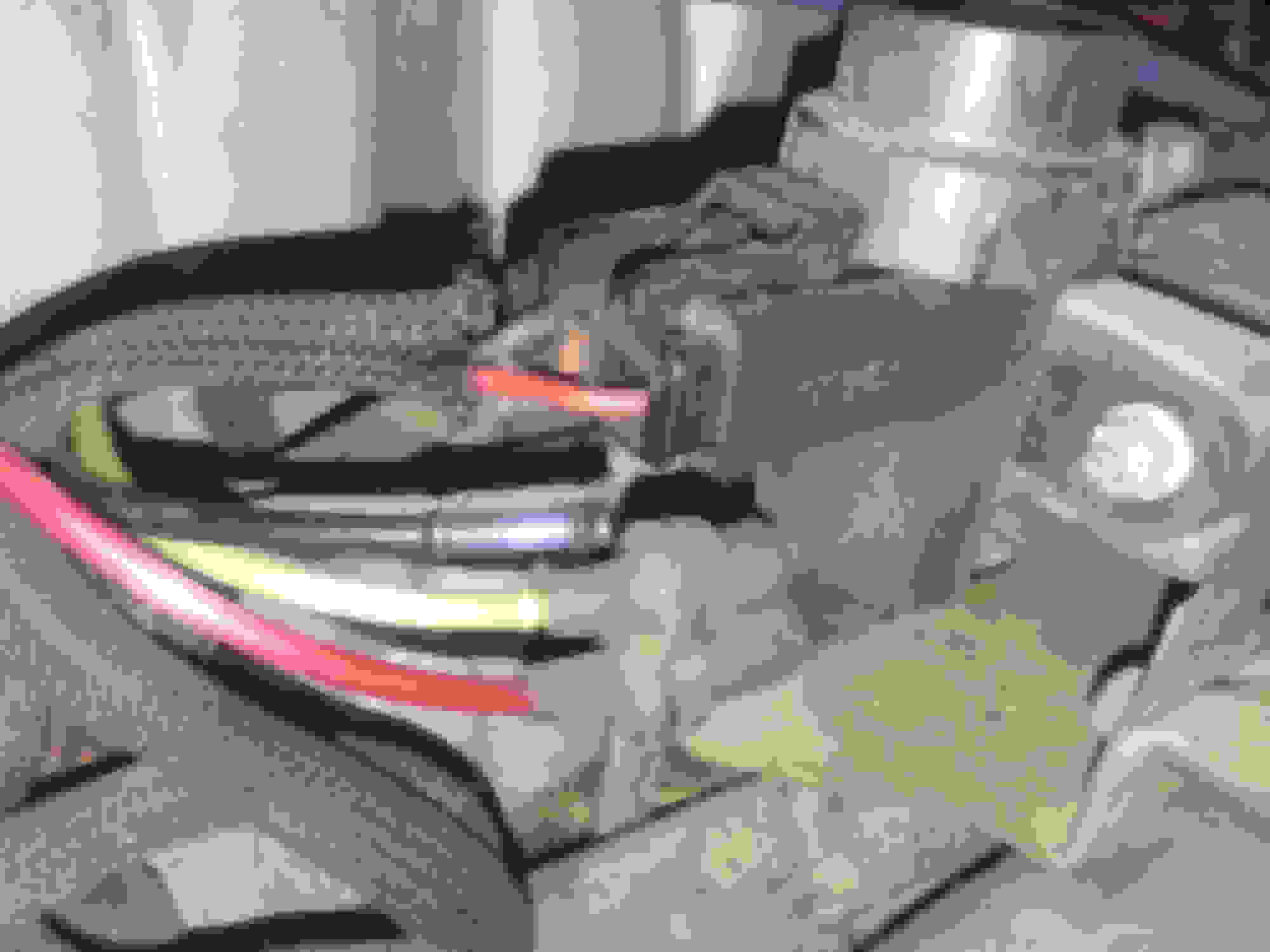
@subford Here are two pics, one is a close up of the solenoid and the lone black vacuum tube
The other is a shot of the solenoid and the ones behind that the black vacuum tube feeds, you can see that there is a orange and a yellow vacuum tube that the
solenoids are switching vacuum too, then the black line carries on to something else I have not been able to see.
!!!!!!! EDIT @subford you were right, I just went crawled over the motor and looked:
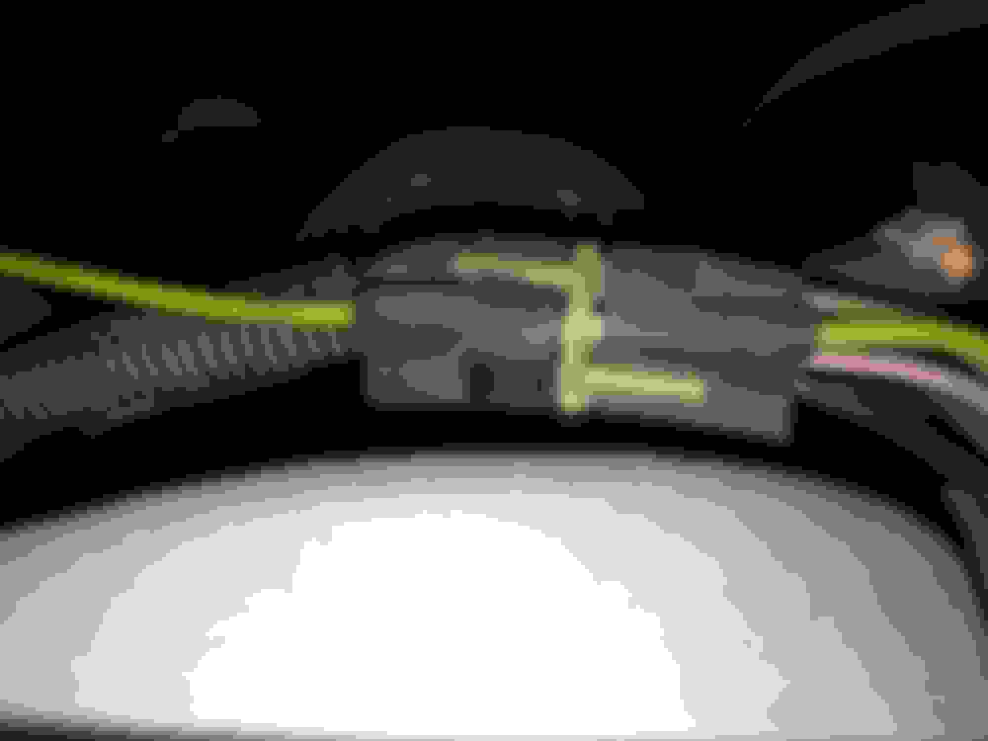
The Black line you see not connected goes to the two solenoids in line supplying vacuum, then to a multi vacuum plug behind the intake, then it goes to the Vacuum Amplifier on the passenger side fender well, I checked to verify and it does directly feed that vacuum amplifier, but may also feed other controls thru the multi vacuum line connecter ??? not sure on that................anyway, would that not indicate it should be run to manifold vacuum ??? And if so what the heck did it go too, maybe the guys that rebuilt the motor forgot and did not re-connect it...........no open ports anywhere and I do not see a place it would have gone, but if it feeds that vacuum amplifier and is supply vacuum for those controls then it should be going to manifold vacuum I am thinking, it does have a couple black lines for manifold vacuum from the intake vacuum tree, but the FPR and the Solenoid in the pic with the green and red are fed with red lines from the intake.
***I disconnected power plug to solenoid in second pic for better viewing
Last edited by n4ynu1010; 02-19-2019 at 04:10 PM.
Reason: correction
It is different than this, my egr vacuum comes from vacuum tree on manifold directly to EGR vacuum solenoid
The red line from the vacuum tree to the FPR is correct
But the Vacuum reservoir is fed with the black line and then it feeds off to the air pump control valve assy everyone calls the octopus
What is the ACV in this diagram ????
I will have to look at this diagram closer and see if I can figure it out in reference to what I actually have ????
This diagram does not show the multi port vacuum connector either ????
Last edited by n4ynu1010; 02-19-2019 at 04:49 PM.
Reason: Addition
@subford
I will have to go to the truck with this diagram and validate operation in reference to controls and what it shows as intake vacuum (supplied) and such and verify it all.
This diagram shows the Reservoir being fed with intake vacuum after a tee and then going back to the controls on the black line, but on mine it is not like this, the Reservoir is fed with a black line which carries intake vacuum and then the other line from the reservoir goes to what would be the bypass valve (all these fitting are factory glued).
The vacuum multi line connector is not shown in this diagram, but the multi line connector does allow the intake vacuum on the black line pass thru so that may not be a issue.
On this motor the red lines from the intake feed only two controls - the EGR Solenoid which then goes directly to the EGR via the green line and also the FPR, these are the only two red lines and the fittings are all glued and factory.
So this means again that this open black line should be manifold vacuum, and I say that because their is no other way for the solenoids and other control valves as well as the reservoir to have any vacuum supply at all unless that un-connected black line is connected to manifold vacuum.
The TAB and TAD are correct except the line going to the ACV is not black, it is orange but does go to the Control Valve behind the intake so it is obviously what is the ACV, which must be a Air Control Valve for the Air Pump Injection or for the CAT Air Injection maybe ???
But still do not know which particular valve the ACV is ????
And all that leaves me with the question since the diagram does not show this for my particular setup, I am just guessing that there was another red line that was connected to this black line and was somehow tee'ed into manifold vacuum ????
On my motor the black line carries on from the TAD and TAB solenoids and like the pic shows ends right in front of the EGR vacuum solenoid, and the vacuum lines going to that solenoid are factory and glued so I do not think there was a tee anywhere there unless it was built into the EGR Solenoid like a second nipple on the body of the solenoid.
So this black un-connected end has to go to manifold vacuum, without vacuum on that line all the others are dead EXCEPT the EGR which is fed directly from the vacuum tree to the solenoid and then directly to the EGR valve via the green line.
Is it possible maybe this truck originally had a EGR Vac. Solenoid with a extra nipple on the manifold intake input for the black tube to connect ???? Maybe someone replaced it with the wrong one ????? I mean the Black line as you see in the pic is curved and bent going right there with the other two, yet the EGR Vac plug (2 line) as you see is factory and glued, so there had to be a separate port or it was tee'ed into something else, but there is nothing there LOL.
In Reality the concept is the same but reversed in my situation, Manifold Vacuum instead of being close to directly feeding the reservoir by the red line is in reality feeding the TAB and TAD from the other end and then carrying that vacuum to the reservoir which would be boosting vacuum for the furthest control which is the Bypass Valve down by the pump and then helping everything in between, not sure if you understand that, but it looks that way.
On the diagram it shows the one red line (manifold vac.) feeding a tee close to the reservoir, I do not have that, and it shows the TAB and TAD solenoids being the end of the end of the vacuum distribution circuit which is not what I have, rather the TAB and TAD vac, feeds are the beginning of this distribution circuit and it has to be factory as the tees in line going to TAB and TAD solenoids are factory and glued, anyway it begins there and then feeds the solenoids, then continues around the back of the upper intake and then to the reservoir and then from there to the Bypass Valve.
I really appreciate the diagram, though it is not the right one according to my motor it does give my a lot of needed info, and though it is confusing, I think I got it all straight, just not the right diagram but the diagram is priceless as it showed me proper routing, not my exact routing but the circuit, and what I have appears to be sort of backwards compared to this but this helped tremendously.
I have seemed to have had this issue with this truck a lot, it seems I cannot find exactly what I have regarding diagrams, it is almost like some type of production anomaly LOL
So two Questions :
What is the ACV
And if I am to connect that end to manifold vacuum what would be best, would it be best to just cut the red line to the EGR solenoid and tee off of that to retain the schematic circuit so to speak or should I use a larger line like the one going to the cruise control diaphram, or I could use the brake booster line, or would any of the above work out fine ????
That is wrong. No Ford truck ever had it routed that way.
Your system should be like the diagram above.
Air Control Valve. See the diagram below.
I think it does and it is what is called the "MAN VAC".
/
Ok, I hear you but the lines are all taped in loom, all of the are factory rubber ends and glued, all molded/bent/curved, there is no way it could be just a couple of connections off, it is completely backwards in reality, but it is all routed and loomed with old tape, it is factory, all the bends follow every thing perfectly........................
Now I am seriously confused, I wish you could see this, you would think the same, and it would not surprise me because not much on this truck from wiring to many other things have been factory diagram specific or in some cases even part specific.
The multi vacuum connector is not on diagram, the tee is not on the truck, and there is no way any of this would be possible to take apart and use on what is there, I mean everything terminates and is bent and curved exact, each fitting is factory glued and correct, the lengths are perfect etc etc, there would only be one way, if someone took a entire circuit off of the wrong truck and used it on this one but then how is every length and connection and bend exact, not to mention factory connectors that are clearly OEM glued.
Not sure, I just think I have a bermuda triangle F150, I have a GMC Jimmy that is the same way and I kid you not, it was owned by a lady, one owner and dealer maintained, just like this truck, and there are things on it that do not match up to any book anywhere, I have to part match, not use part per year make model.
Anyway, my last post pretty much spells it all out, I am going to feed the end with manifold vac., then it will feed the TAB and TAD immediately and crossover behind intake to feed the reservoir, then to the bypass, if it does not work I will just rip it all out and rework it with tubing.
But see that is another thing that makes it virtually impossible for me to believe is how could that work out if it is not factory...............the line comes around the motor intake, terminates at the reservoir then goes to the bypass valve, perfectly right plugs, right length, right color, molded perfectly, every other control is the same with exception of the ACV, the color is not black, it is orange.
So I am confused but will try it like I explained in the other post, if I have issues I will just rework the entire vac. system
Also, Thanks for that Diagram too, I appreciate it, going to save it as well.
I think it does and it is what is called the "MAN VAC".
It would appear MAN VAC is the Intake vacuum tree on the diagram, what I was talking about is a multi line vacuum connector, it is behind the upper intake and is like a vacuum harness union where you could separate/unplug it, would be useful for checking diaphragms in valves that are hard to reach.
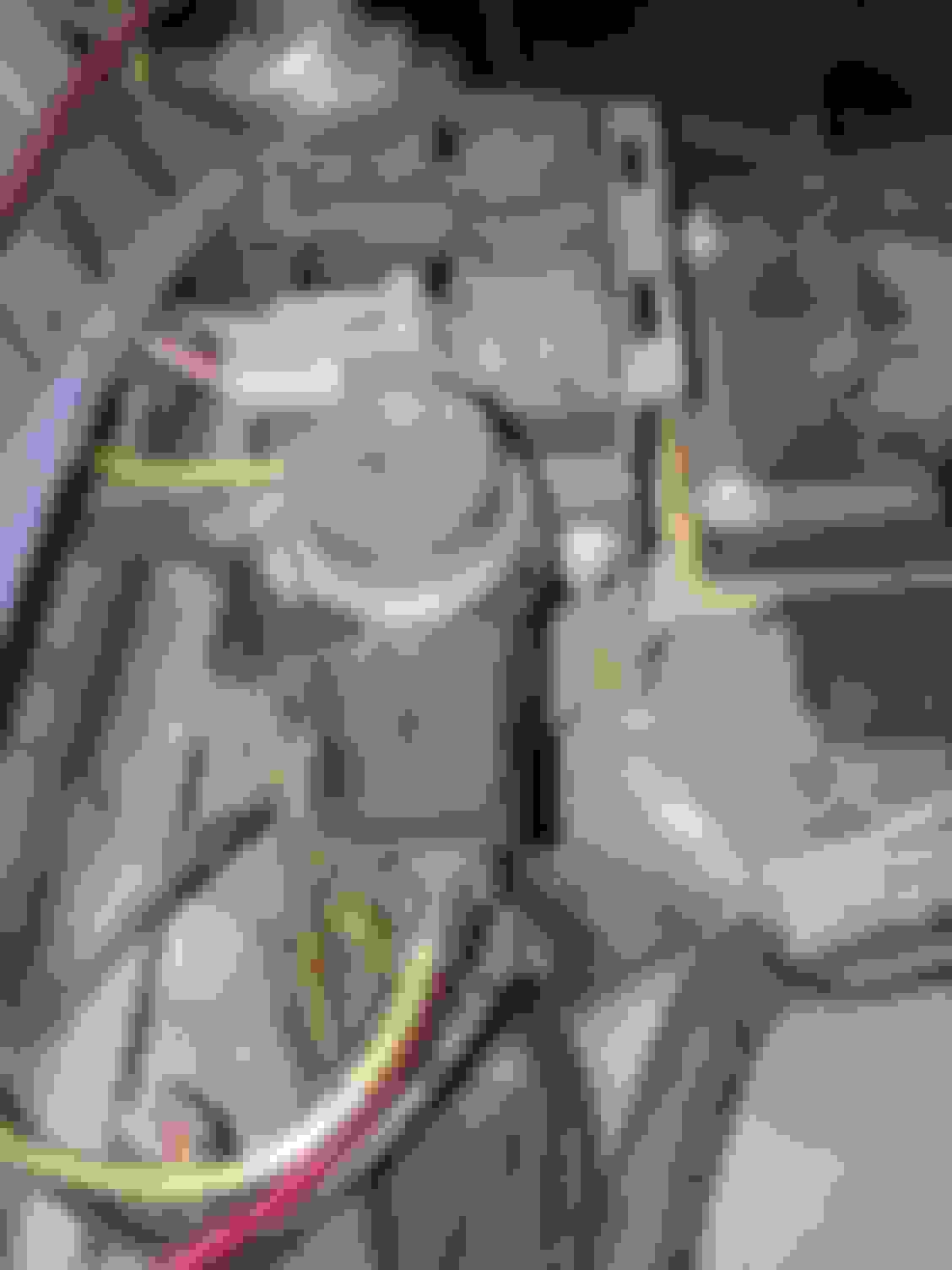
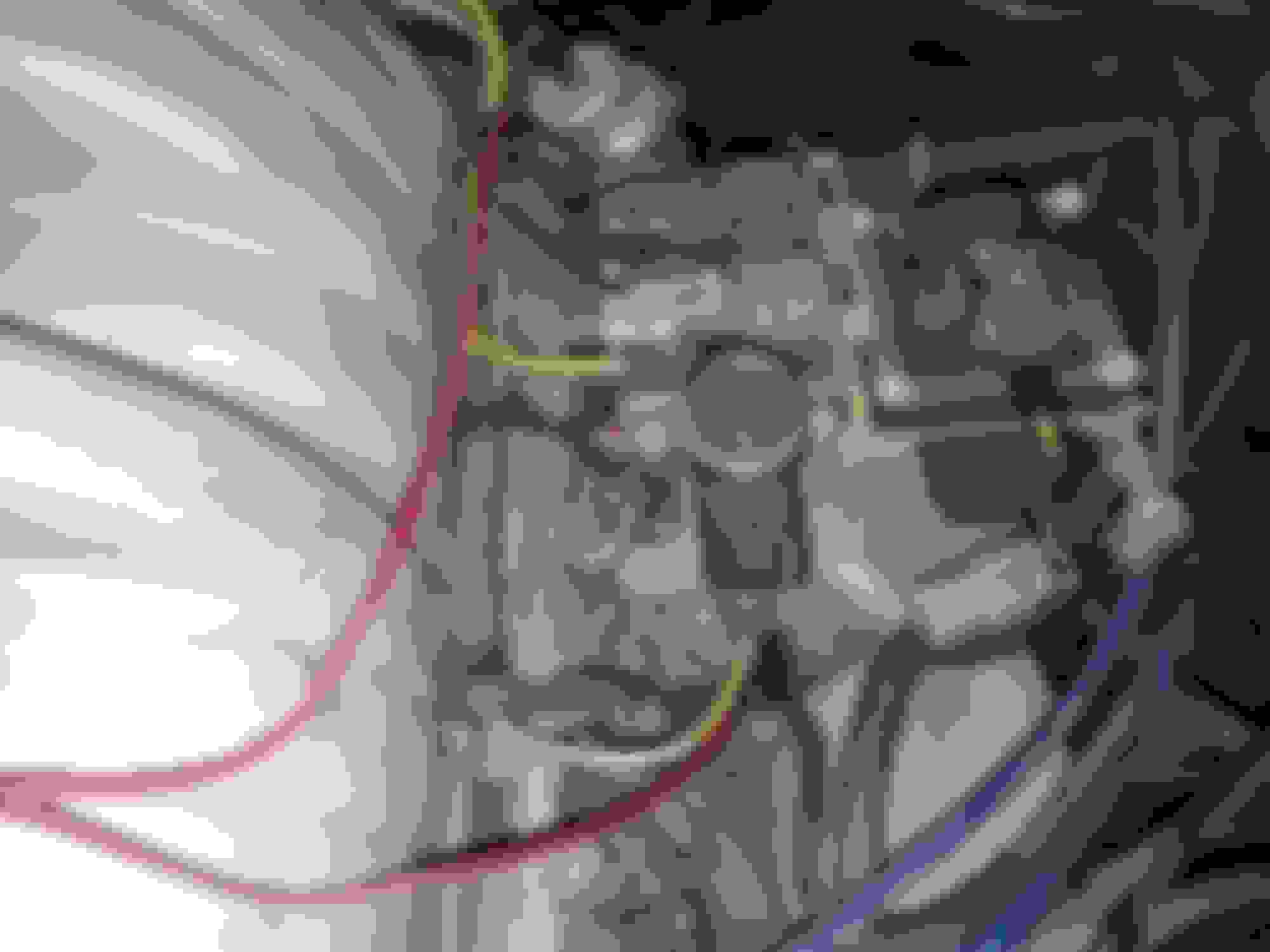
@subford
Here are two pics, one of the connector behind the intake, the other is a top view so you can see the routing and you can see the red line feeding the EGR Vac. Solenoid, you can also see the TAB and TAD lines, all OEM, all in perfect order, hard to believe this is not factory ...................just trying to help you understand I am not crazy LOL
I disconnected power plug from EGR Solenoid and removed Brake Booster and Cruise Vac. Lines and the Coil wire for a better view.
I would think the black line went to the EGR solenoid and the red wire would go some place else.
The only problem is it is factory glued, I have tried to remove it and swap but it nor the green one are coming out unless something is damaged, this is what I am saying, it is like backwards, but it should still work if I connect the black to manifold Vac, but what would be the best source, the cruise vac line, brake booster vac line or just cut the red line going solenoid and put a tee in there ???
I really appreciate your help man, I am telling you it is a Bermuda Triangle F150 LOL
I have not found another layout like this and I have searched everywhere, but the rest is just like that, perfect lengths, bends and fittings, I find it hard to believe it did not come that way, maybe it was made on a monday and some guy with a serious hangover did it ROFLOL, may have still been drunk LOL

 02-19-2019, 01:51 PM