


60mph uphill @ 18000rpm w 8k lb
Post Fiend
Joined: Feb 2007
Posts: 14,541
Likes: 2
From: Dallas-Ft. Worth
That's an excellent point. I don't recall if I had smoke or not. That right there is what it boils down to -- if you have enough air to burn all the fuel at 22psi, 27psi won't help anything. I'm thinking I had better acceleration, but you're right -- I could've been killing myself on the top end by making the engine work too hard to overcome the BP. It would be interesting if someone could watch boost, backpressure, and EGTs with it hooked and unhooked. It would also be interesting to do that on a dyno. Wait, isn't that what Gene was asking about?? LOL
Postmaster
Joined: Jun 2006
Posts: 2,647
Likes: 0
From: Fulltime RVer

By bypassing some of the exhaust flow you wind up with less "mass per unit time" flowing through the turbine restriction but due to the increase in EGT this reduced mass flow contains the same amount of "heat energy per unit time" and the total amount of heat energy per unit time is what actually powers turbine to drive the compressor to produce a given boost!
However if you only consider just the combined "intake-exhaust stroke" as defined above then operating an engine with no "pumping loss" is a "Thermodynamic impossibility" because in order to have no "pumping loss" the mass of exhaust gas pumped out by the piston during the "exhaust stroke" needs to be a factor of MAT/EGT (absolute values) smaller than the mass of air pumped in by the piston during the "intake stroke"!
This MAT/EGT constraint results because to have no "pumping loss" the "intake flow energy" going into the cylinder during the "intake stroke" must be equal to the "exhaust flow energy" coming out of the cylinder during the "exhaust stroke" and the "intake flow energy" is directly proportional to the absolute value of the MAT and the "exhaust flow energy" is directly proportional to the absolute value of the EGT!
As an example of what this means consider a "sustained BP=21 psig" which gives the typical values MAT=148*F=608*R and EGT=1,040*F=1,500*R, where *R=*F+460, and since (608/1,500)=0.40 or 40% this says that to have no "pumping loss" only 40% of the mass that flows out of the intake manifold and into the cylinder during the "intake stroke" can flow back out of the cylinder during the subsequent "exhaust stroke" and into the exhaust manifold! So if you want to have no "pumping loss" you need to account for the other 60% of the original "intake stroke" mass!
Well the "exhaust valve" begins to open well before BDC of the "power stroke" and this allows a "pulse of mass" to be ejected from the cylinder before the "actual exhaust stroke" begins and this "pulse of mass" is what conserves the overall net mass flow between the intake and exhaust manifolds! This "pulsed ejection of mass" is called the "exhaust blow-down phase" of the "exhaust stroke" which is somewhat of a misnomer since "blow-down" actually occurs during the "power stroke"! These short duration ejections of mass create pressure pulses which combine with the more steady pressure released during the "actual exhaust stroke" and the time-averaged pressure is equal to the EBP seen on a gauge.
A combination of "injection timing" and "cam timing" and a number of "other factors" determine how much of the turbine drive power comes from the "exhaust blow-down" phase of the "power stroke" and exploiting this "blow-down" effect is what reduces the value of EBP needed to produce a given BP! I derived some equations that describe "exhaust blow-down" and eventually I'll include those on my turbo thread.
If the EBP is larger than the BP then the "pumping loss" increases and during the valve overlap interval in the vicinity of TDC between the exhaust stroke and the intake stroke some "exhaust gas" is pushed back into the intake plenum and then re-ingested into the cylinder during the intake stroke and this "reduces" the "effective displacement" of the engine. On the other hand if the BP is larger than the EBP you get a "pumping gain" and during the valve overlap interval in the vicinity of TDC between the exhaust stroke and the intake stroke some "fresh air" is pushed into the "clearance volume" above the piston and this "increases" the "effective displacement" of the engine.
"Turbochargers HP49 (HP Books): Turbo Design, Sizing & Matching, Spark-Ignition & Diesel Engine Applications, Water Injection, Controls, Carburetion, Intercooling, ... Street & Race Cars, Boats, Motorc"
Hugh MacInnes; Paperback; $14.93
"Maximum Boost: Designing, Testing, and Installing Turbocharger Systems (Engineering and Performance)"
Corky Bell; Paperback; $23.07
"Turbo: Real-World High-Performance Turbocharger Systems (S-A Design)"
Jay K. Miller; Paperback; $16.47
None of the books do a good job of explaining how a turbo actually works which is why I started my thread on that subject. I'm only posting the graph below to see if it works because I want to use something like this when I explain "heat energy"!

Postmaster
Joined: Jun 2006
Posts: 2,647
Likes: 0
From: Fulltime RVer
...Thanks for posting that. I've been reading about all of the rigging of the wastegate and something about it seemed really fishy to me. I'd actually like to know some good reasons to definitely keep it connected. If you install a WW, do you have to adjust it at all?...
I'm not sure if people trust my computer model graphs more or less than graphs from Banks but the two graphs below both give the same results and both graphs show that the stock turbo with its crappy L99.5 wheel is very susceptible to surge especially in the lower RPM range which you have to transition through when starting up from a stop and when shifting through each gear.

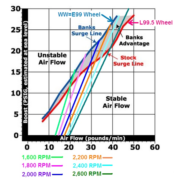
On either graph if you follow up vertically from a MAF=14 lb/min until you hit the red surge line you'll see that surge is encountered at a BP=8 psig and that's why the stock wastegate begins to open when the BP increases to only a BP=8 psig which many think is too low but it's actually the correct BP value to match the surge characteristics of the stock wheel!
In addition to being controlled by the MAP sensor the ECM/PCM also uses the VSS to control the wastegate and it keeps the wastegate wide open for vehicle speeds below about 5 mph. This not only controls surge when starting up from a dead stop but it also reduces the EBP during idle and slow speed operation and this increases your MPG!
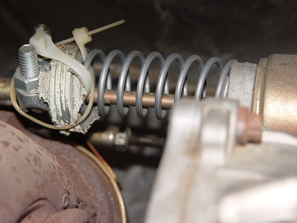
Some chips and programmers modify the ECM's wastegate control strategy to the point where the wastegate doesn't open wide enough at WOT and to counter that effect I installed the self-calibrated "helper spring" shown below. After I switched from a Superchip to a DP Tuner I discovered that DP's management of the wastegate was more to my liking and I removed the "helper spring".

Senior User
Joined: Oct 2006
Posts: 259
Likes: 0
Hey ernesteugene, do you happen to know the spring pressure of the wastegate actuator? [edit]: I'm going outside to test it
Unless it's a really low pressure that allows EBP to open the gate itself, the wastegate can't be open at idle or near idle conditions because there's no boost against the diaphram in the actuator to overcome spring pressure.
If there's anything specific you wanted tested on a dyno, I'd be happy to help. I have access to a dyno dynamics eddy current dyno that I work at and has the ability to hold an RPM as you increase load, which would be awsome for testing proper wastegate functions.
If you invert the dutycycle of the wastegate actuator solinoid (the signal, not the solinoid), you can use it and reconfigure the system to eliminate the bleeder system and have the solinoid directly control the pressure in the actuator and still have stock boost control without the boost leak. Since ust inverting the signal is not accurate enough because of the changes in config mean the system's equalibrium is different [25% DC in one config may not produce the same BP as 75% DC in the other], an electronic boost controller my be needed, or the programming in the ECM modified, which brings me to my next question. Who knows exactly what the programming of the solinoid is? I'd bet it's not even a 3D map, but a 2D map, as in "if BP is x, DC is y", with modifiers, "if BP is x, Mass demand is y, DC lookup is z, than DC is 1.5z". While thinking about it, I doubt it's that specific, probably just similar to "keep solinoid open until BP rises above x, then increase DC until 100% at BP = y, unless fail/limp mode, in which DC = 0%". Typical of factory turbo gas programming.
Can the AE access solinoid DC? It would be easy to build a map from datapoints if it did, then we can rest this case for good. Now I just need an AE, lol, 'nother $400 down the drain...
Postmaster
Joined: Jun 2006
Posts: 2,647
Likes: 0
From: Fulltime RVer
...I guess the question is whether or not the extra backpressure overrides extra boost with it unplugged. Or conversely, does the loss of backpressure compensate for loss of boost with it plugged in...
...I'm seeing about 35psi boost, and about 45psi of backpressure... I'll look at it again when I have a chance and get more accurate numbers...
...I'm seeing about 35psi boost, and about 45psi of backpressure... I'll look at it again when I have a chance and get more accurate numbers...
Well this is why "equations" are a "necessary evil" if you want to answer questions like this and here's an equation you can use to calculate the answers after you make additional measurements of the BP and the EBP at a given operating condition which also includes the RPM! The PLHP=Pumping Loss HP is given by...
PLHP={(EBP-BP)(RPM)(CID)}/(792,000) hp
...so plug in EBP=45 psig, BP=35 psig, CID=444 in^3, and I'll guess your RPM was 3,000 rpm when you measured these EBP and BP values. This gives... PLHP={(EBP-BP)(RPM)(CID)}/(792,000)={(45-35)(3,000)(444)}/(792,000)=16.8 hp!
So having the EBP higher than the BP by 10 psi incurs a "pumping loss hp penalty" of about 17 hp "but" this is only "part" of the overall "total hp penalty" for having the EBP 10 psi higher than the BP because if you compare to a case where the EBP is say only 1 psi less than the BP then you get a "pumping gain" of 1.7 hp which is nothing to brag about but you also get a 10% to 15% increase in the "effective displacement" of the engine by completely filling the "swept volume" of the cylinder and the "clearance volume" above the piston with fresh air during the intake strokes as compared to re-ingesting stale exhaust gas which is what happens when the EBP is higher than the BP!
For a 17.5 to 1 compression ratio filling the "clearance volume" above the piston with fresh air provides a (1/17.5)=(0.057) or a 5.7% increase in the "effective displacement" of the engine and depending on the exact amount of exhaust gas that's forced to backup into the intake plenum and then be re-ingested during the intake stroke when the EBP is 10 psi higher than the BP you might easily get an additional 5% to 10% increase in the "effective displacement" of the engine for a total increase of 15% or more!
Now the amount of additional hp that's actually produced by this 10% to 15% increase in the "effective displacement" of the engine depends on the AFR but if the fueling is adjusted to optimally use the increase in "effective displacement" then "in principle" a 10% to 15% increase in maximum hp can be obtained!
Post Fiend
Joined: Feb 2007
Posts: 14,541
Likes: 2
From: Dallas-Ft. Worth
Excellent info. I'm actually asking not because I want to INCREASE my HP, but I actually WANT that penalty in there for now. The injectors I have are big enough to support over 500 rwhp -- the block won't handle it. I'm actually using the van turbo as sort of a regulator right now. If I was interested in max efficiency, I'd address that. For now, I'm okay with it being "choked", for lack of better term.
I already know I have seen an increase in efficiency with the hybrid injectors when driven "nicely". I managed 22.1 mpg running 70 mph for 3 hours (about 210 miles) between Austin & Dallas. My previous best was just under 20.
So for now, I'm okay with the situation I'm in, for PMR protection. LOL
I already know I have seen an increase in efficiency with the hybrid injectors when driven "nicely". I managed 22.1 mpg running 70 mph for 3 hours (about 210 miles) between Austin & Dallas. My previous best was just under 20.
So for now, I'm okay with the situation I'm in, for PMR protection. LOL
Postmaster
Joined: Jun 2006
Posts: 2,647
Likes: 0
From: Fulltime RVer
..."At idle or WOT in park or neutral duty cycle will be ~0.11% (wastegate open). At about 5 mph the duty cycle will go to 90-100% and the wastegate will be closed (pressure dumping back to intake via green line). As Manifold Gauge Pressure climbs duty cycle will decrease and the solenoid will close the dump valve and apply pressure to the wastegate actuator opening the wastegate."...
Here's the entire 2 page document below...


The title of the top screen in the second page is... Wastegate at Idle" ...and the title of the middle screen is... "Wastegate closed starting acceleration" ...and the title of the last screen is... "Wastegate Opening under acceleration" ...so it appears that AE can read the solenoid DC!
FTE Stories
Ford Trucks for Ford Truck Enthusiasts

Top 6 Best Deals Available on New Fords & Lincolns Right Now
Brett Foote
This Hennessey Takes the Expedition Tremor's Off-Roading Capability to the Next Level
Verdad Gallardo
Top 10 Fords at 2026 Carlisle Ford Nationals
Joe Kucinski
3 Best / 3 Worst Parts of Modern Ford Ownership
Brett Foote
10 Amazing Upgrades That Solve Common Ford Truck Owner Headaches
Pouria Savadkouei
Every 2026 Ford Engine Explained
Brett Foote
10 Ugly Ford Trucks That We Still Kinda Love
Joe Kucinski
10 Things Every Truck Owner NEEDS (2026 Edition)
Michael S. Palmer
Rezvani's Latest Post-Apocalyptic Monster Is a Ford F-150 Raptor Underneath
Verdad GallardoPostmaster
Joined: Jun 2006
Posts: 2,647
Likes: 0
From: Fulltime RVer
Well you won't be LOLing when you hole the block! Producing a given FWHP with excessive EBP "increases" the stress on the rods because the power stroke needs to be powerful enough to produce the FWHP and overcome the EBP!
Post Fiend
Joined: Feb 2007
Posts: 14,541
Likes: 2
From: Dallas-Ft. Worth
That's why I watch it, Gene. I watch that and my EGTs and get out of it when it gets too high. Which is kind of what I meant. I have to get out of it manually for now -- once I get my tuning set up, I won't have to.
Postmaster
Joined: Jun 2006
Posts: 2,647
Likes: 0
From: Fulltime RVer
CSHP*={(VE)(CID)(RPM)(BP-BP*)}/(173,000) hp
I'm very familiar with this "penalty hp" because it's a "designed in feature" on my C7 which has a maximum FWHP=300 at an RPM=2,200 and this FWHP could easily be produced without any smoke at all by using an actual BP=22 psig but in order to meet the 2003 NOx emissions without using EGR CAT runs the wastegate so that the turbo produces a BP=28 psig! This gives a... CSHP*={(VE)(CID)(RPM)(BP-BP*)}/(173,000)={(0.8)(442)(2,200)(28-22)}(173,000)=27 hp!
In addition to placing additional stress on the rods this 27 hp "emissions penalty" also increases the fuel consumption by 1 MPG compared to the older 3126 which runs at a lower BP for the same 300 FWHP! Of course if CAT had used EGR to meet emissions there'd also be a 27 hp "emissions penalty" and I'd rather have the extra fresh air going into the cylinders instead of exhaust gas!
In your case we concluded that you've got a 17 hp "pumping loss" penalty due to running a BP=35 psig versus an EBP=45 psig and if that BP=35 psig is say 6 psi higher than you actually need to produce your FWHP at 3,000 rpm then your additional "excessive BP" penalty is... CSHP*={(VE)(CID)(RPM)(BP-BP*)}/(173,000)={(0.8)(444)(3,000)(35-29)}(173,000)=37 hp and that means you've got a total "penalty hp" of 17+37=54 hp!!!
Hint... I'm hoping someone asks me to explain how I came up with the above equation and the previous one... PLHP={(EBP-BP)(RPM)(CID)}/(792,000) hp ...because there's some interesting "Thermodynamics" involved in deriving them!
Cargo Master

Joined: Jan 2001
Posts: 2,726
Likes: 5
From: Slatington, PA
Ok, I'll bite that hook. How'd you come up with that equation? I really do enjoy trying to figure out your posts. The charts help a lot.
Post Fiend
Joined: Feb 2007
Posts: 14,541
Likes: 2
From: Dallas-Ft. Worth
Just so we're clear, that penalty only comes into play when I'm hitting it hard, so under "normal" driving conditions, I'm getting better mileage than I did with my stock split-shot injectors. Obviously I'll get LESS MPG when I'm nailing it -- I now have the ability to dump nearly 2x the fuel through the injector! 140cc vs. 235cc with 100% over nozzles.....

New User
Joined: Oct 2009
Posts: 1
Likes: 0
Be careful
Be Careful thread readers, posts from ernesteugene are not all accurate relative to physics and relative to opinion. This guy is despirately trying to wow the world by trying to impress people with his math skills. The three books he slams is one way of him trying to elevate his image. Hugh McInnes' book was written by a man, now deceased, who was very revered throughout the industry, Corky Bell's Book is a market Standard, and the book TURBO is the best new book on the market, and the only one that received a silver medal in the International Automotive Media Awards. Specifically TURBO goes into how a turbo works more then any of the others. So, be cautious of what you rwead in here, so of the perspectives are wrong, and only an opinion. It would appear that this person does not understand the general audience these books were written for.
Anyone who professes to be a wizard, while slamming other published authors is suspect. Remember, this is the web.
TJ
Anyone who professes to be a wizard, while slamming other published authors is suspect. Remember, this is the web.
TJ
Postmaster
Joined: Jun 2006
Posts: 2,647
Likes: 0
From: Fulltime RVer
Since I've been posting on this forum for several years now I think most members know that my primary goal here is to explain "using equations" how things work so that we can make some "calculations" to provide a "deeper insight" into topics of interest and get some "numerical estimates" to answer questions like how much performance penalty is there if you run a BP=35 psig with an EBP=45 psig. Now just to refresh everyone's memory here's what I said about the three books in question...
...The first (and cheapest) book is by far the best and even though the last book has a glowing introduction by "Banks" it's by far the worst! None of the books do a good job of explaining how a turbo actually works which is why I started my thread on that subject...
Apparently you rated the book "TURBO" by Jay K. Miller as the "best" of the three because its new and it won some kind of an award so I'll give you one "technical example" for why I rated it the "worst"! At the bottom right of page 19 you'll find this statement...

Now I understand the need to sometimes make explanations less than "100% technically correct" in order to make them easier to understand but for an "engineer" like "Miller" to say that the "First law of Thermodynamics" is the "Ideal gas law" is simply inexcusable and by reading such a statement no one is going to learn how a turbo really works from a "Thermodynamics perspective"!
As I've already explained in my turbo thread in 1843 James Joule performed a classic experiment in which he "discovered" the "First law of Thermodynamics" which is the equivalence of "heat energy" and mechanical "work energy" and this "First law" is in fact the basis for explaining how both the compressor and turbine sections of a turbo function "but" the "First law of Thermodynamics" has nothing whatsoever to do with the "Ideal gas law"!
Lets review some history on this subject... In 1834 Emil Clapeyron was the first person to actually write the "Ideal gas law" in the form of an "equation" and this was 9 years "before" Joule discovered the "First law of Thermodynamics" in his classic experiment but Joule didn't call it the "First law of Thermodynamics" until sometime after 1849 which is when Joule coined the term "Thermodynamics"!
Also the "Ideal gas law" is really a combination of three empirical "gas laws" that were individually discovered by Robert Boyle, Jacques Charles, and Amedeo Avogadro years before Clapeyron combined them to form the "Ideal gas law equation" so there's at least a 15 year gap between general knowledge of the "Ideal gas law equation" and the "First law of Thermodynamics"!
Well what I'd like to comment about your "top rated book TURBO" is that I've seen most of the pictures in it and some of the words posted on various turbo websites I've visited but "I won't actually make that claim" because I might get sued. I will make the general statement that there's a lot of misinformation and downright incorrect information posted on some turbo websites and if that "same" information should appear in a book it's still just as misleading and or incorrect as when it was posted on the internet!
Well my original quote didn't even come close to being a "slam" against any of the 3 books but hopefully this post qualifies as a slam against the one you rated as the best! However I encourage everyone to still get all three books as part of the Amazon package deal and then compare the explanations in them with the ones on my turbo thread!