94 7.3 turbo idi injection return lines
#1
 09-21-2010, 02:40 PM


Join Date: Mar 2006
Posts: 106
Likes: 0
Received 0 Likes
on
0 Posts
94 7.3 turbo idi injection return lines
ok well i have had this truck apart for about a year and a half so i am trying to put the new fuel injector on it an new return lines an its been apart for so long i am not shore of the cap placement an fuel line routing from what i no the 94 turbo idi is different than the non turbo idi . i have a 94 turbo idi so any help would be great . even if some one has a pic of a 94 turbo idi that would be great
#2
09-21-2010, 06:35 PM

Join Date: Mar 2009
Location: Maine (NorCal Native)
Posts: 6,442
Likes: 0
Received 5 Likes
on
5 Posts
They are routed different and in my opinion it is wrong ...
The ultimate (or proper IMO) return setup would be ... (using a 7.3 NON turbo Installation kit)
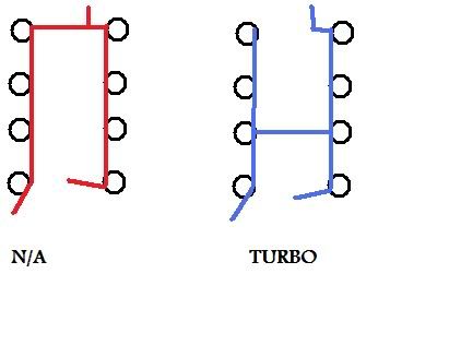
The return line from the IP goes to the first Injector on the left bank through all the Injectors to a return tee at the back of the motor ... This allows air to bleed from the IP as well as coolant for the left bank of Injectors!
The return line from the filter head goes to the first Injector on the right bank and through all the Injectors to the return tee at the back of the motor ... This allows air to bleed from the filter as well as coolant to the right bank of Injectors!
The POOR factory Turbo return line layout ...

The factory Turbo layout #7 Injector uses a Tee with one barb and the #5 Injector has a 3 barb Tee, the third barb is the crossover ... This leaves #7 dead headed without flow, A very poor layout!
This is done to keep the lines away from the heat of the turbo ... It can be done with my suggested routing using a longer hose and routing it from #7 back towards the front of the truck around the front of the intake to the brass tee at the back of the motor.
-Enjoy
fh : )_~
The ultimate (or proper IMO) return setup would be ... (using a 7.3 NON turbo Installation kit)
The return line from the IP goes to the first Injector on the left bank through all the Injectors to a return tee at the back of the motor ... This allows air to bleed from the IP as well as coolant for the left bank of Injectors!
The return line from the filter head goes to the first Injector on the right bank and through all the Injectors to the return tee at the back of the motor ... This allows air to bleed from the filter as well as coolant to the right bank of Injectors!
The POOR factory Turbo return line layout ...
The factory Turbo layout #7 Injector uses a Tee with one barb and the #5 Injector has a 3 barb Tee, the third barb is the crossover ... This leaves #7 dead headed without flow, A very poor layout!
This is done to keep the lines away from the heat of the turbo ... It can be done with my suggested routing using a longer hose and routing it from #7 back towards the front of the truck around the front of the intake to the brass tee at the back of the motor.
-Enjoy
fh : )_~
#3
09-21-2010, 08:27 PM
Join Date: Mar 2006
Posts: 106
Likes: 0
Received 0 Likes
on
0 Posts
#4
09-21-2010, 08:48 PM
Postmaster
#5
09-21-2010, 09:12 PM
Join Date: Mar 2009
Location: Maine (NorCal Native)
Posts: 6,442
Likes: 0
Received 5 Likes
on
5 Posts
I do not have an image, however I did describe it ... If you do my described method (as quoted below) you need to get a Injector Installation kit for a NON Turbo.
-Enjoy
fh : )_~
The ultimate (or proper IMO) return setup would be ... (using a 7.3 NON turbo Installation kit)
The return line from the IP goes to the first Injector on the left bank through all the Injectors to a return tee at the back of the motor ... This allows air to bleed from the IP as well as coolant for the left bank of Injectors!
The return line from the filter head goes to the first Injector on the right bank and through all the Injectors to the return tee at the back of the motor ... This allows air to bleed from the filter as well as coolant to the right bank of Injectors!
fh : )_~
#7
09-21-2010, 10:21 PM
Join Date: Mar 2009
Location: Maine (NorCal Native)
Posts: 6,442
Likes: 0
Received 5 Likes
on
5 Posts
Trending Topics
#12
09-22-2010, 04:01 AM
Join Date: Mar 2006
Posts: 106
Likes: 0
Received 0 Likes
on
0 Posts
i have both kits so i can do it ether way so i am going to try to do it the non turbo way it looks better.ok one last question i see on oreocreaming's drawing the non turbo one . the bottom of picture left side go to filter housing and right side go to injection pump am i right so far ? now up the top of picture were does that end go ? i am sorry for dumb questions but its been a long time since i played with this truck . thanks for info guys
#13
09-22-2010, 11:09 AM
Join Date: Mar 2009
Location: Maine (NorCal Native)
Posts: 6,442
Likes: 0
Received 5 Likes
on
5 Posts
The layout I described is exactly how Oreo's N/A layout is depicted ...
The return line from the IP goes to the first Injector on the left bank (US drivers side) and through all the Injectors to the brass return tee at the back of the motor ... This allows air to bleed from the IP as well as coolant for the left bank of Injectors!
The return line from the filter head goes to the first Injector on the right bank (US passenger side) and through all the Injectors to the brass return tee at the back of the motor ... This allows air to bleed from the filter as well as coolant to the right bank of Injectors!
So, That means in Oreo's picture, the lower right goes to the IP, the lower left goes to the filter head, the top is the back of the motor, Thus that would be the BRASS Tee at the back of the motor, That brass Tee has 3 connections, two 1/4" barbs and one 5/16" barb, one 1/4" barb is for the Left bank, one 1/4" barb is for the Right bank and the 5/16" barb heads back to the fuel tank. (through the Fuel Selector Valve if you have dual tanks)
Hope this clears it up for you, if not I'll try and try again ...
-Enjoy
fh : )_~
#14
09-22-2010, 11:44 AM
Postmaster
Join Date: Oct 2005
Location: Clarksburg WV
Posts: 3,724
Likes: 0
Received 0 Likes
on
0 Posts