Who is the electrical Wizard? OE 6V.
#16
 03-26-2010, 01:39 AM


Post Fiend
Julie Thanks,
I had some time today so I'm checking my wiring. comparing the last diagram (circuit breaker) to my actual circuit box, how do I tell which is the 30s and which is the 15s? It says right on them. Well, anyhow thinking the 30s is the lower post. I ran the 30s lower post to the Battery of the regulator. Than I ran from the 15s, upper post, thru the ammeter with a 10 gauge wire, over to the B terminal of the starter Solenoid. Sounds good - just like the picture right? Is there supposed to be a wire joining the upper and lower post? I wouldn't think so but what does that maroon line mean? the one from the 30s to the 15s.
I had some time today so I'm checking my wiring. comparing the last diagram (circuit breaker) to my actual circuit box, how do I tell which is the 30s and which is the 15s? It says right on them. Well, anyhow thinking the 30s is the lower post. I ran the 30s lower post to the Battery of the regulator. Than I ran from the 15s, upper post, thru the ammeter with a 10 gauge wire, over to the B terminal of the starter Solenoid. Sounds good - just like the picture right? Is there supposed to be a wire joining the upper and lower post? I wouldn't think so but what does that maroon line mean? the one from the 30s to the 15s.
#17
03-26-2010, 06:02 AM

Join Date: Sep 2008
Location: Whiting, NJ
Posts: 90
Likes: 0
Received 0 Likes
on
0 Posts
OE 6v...
"I had some time today so I'm checking my wiring. comparing the last diagram (circuit breaker) to my actual circuit box, how do I tell which is the 30s and which is the 15s? Well, anyhow thinking the 30s is the lower post. I ran the 30s lower post to the Battery of the regulator. Than I ran from the 15s, upper post, thru the ammeter with a 10 gauge wire, over to the B terminal of the starter Solenoid. Is there supposed to be a wire joining the upper and lower post? I wouldn't think so but what does that maroon line mean? the one from the 30s to the 15s."
It's not easy to find a 30 amp ammeter today. You'll probably wind up using a shunt resistance & measuring voltage across that. It's much easier but less accurate to use the existing ammeter of the gauge cluster provided the wire that runs through the ammeter's induction loop is in good shape.
The maroon line on Julie's diagram that runs between "30s & 15s" is probably a brass or copper rectangular bar that join the two circuit breaker posts.
I've attached a picture of the back of my speedometer & gauge cluster. The circuit breakers are to the right. Hope this helps...
#18
03-26-2010, 06:04 AM
Join Date: Sep 2008
Location: Whiting, NJ
Posts: 90
Likes: 0
Received 0 Likes
on
0 Posts
#19
03-26-2010, 10:53 AM
Post Fiend
"I had some time today so I'm checking my wiring. comparing the last diagram (circuit breaker) to my actual circuit box, how do I tell which is the 30s and which is the 15s? Well, anyhow thinking the 30s is the lower post. I ran the 30s lower post to the Battery of the regulator. Than I ran from the 15s, upper post, thru the ammeter with a 10 gauge wire, over to the B terminal of the starter Solenoid. Is there supposed to be a wire joining the upper and lower post? I wouldn't think so but what does that maroon line mean? the one from the 30s to the 15s."
It's not easy to find a 30 amp ammeter today. You'll probably wind up using a shunt resistance & measuring voltage across that. OK you need to stop telling folks to measure voltage, that is not correct - and you measure amperage, it needs to be done with a multimeter or a charging system analyzer - not an automotive gauge. You can get an analyzer at Sears or for about $3 at any swap meet. It's much easier but less accurate to use the existing ammeter of the gauge cluster provided the wire that runs through the ammeter's induction loop is in good shape. The ammeter installed in the truck will give you an indication of whether or not the generator and regulator are putting out a charge - that's all. It might not be enough of a charge.
The maroon line on Julie's diagram that runs between "30s & 15s" is probably a brass or copper rectangular bar that join the two circuit breaker posts.
I've attached a picture of the back of my speedometer & gauge cluster. The circuit breakers are to the right. Hope this helps...
In your pucture, the only thing the circuit breakers are being used for is as a mounting stud to hook a bunch of wires too. So, if the truck is 6 volt and you want stuff to have CB protection then they should be powered off the "AUX posts of the CBs. The generator wiring the way you have it should work as long as the large wire running through your ammeter is going out of the "BATT" post of the starter solenoid - the same post the negative battery cable is hooked up to. But you need to flow the rest of your wiring as shown in the drawing below. What ever the wire is that you have hooked up along with those two - with the blue shrink wrap, needs to come off of there and get run out of the "AUX" post of one of the breakers. As it is it is subject to the pull and unprotected output of your generator.
Power to your ignition switch should flow off the circuit breakers, and then power for the gauges should flow back from the "ACC" post of the ignition switch. I'm not seeing any of that - maybe you aren't that far yet. If it is 12 volt, you should have a fuse panel installed and have the power distribution running off of that.
The metal shunt appears to be in place between the two. The 30 amp and 15 amp labels are cast into the bakelite backs of the Circuit breakers - under the cardboard.
Here's a picture of the 51/52 CBs. The only difference is how they are mounted. Disregard the hook up notes on the photo - they were for another post.
Your panel is 48-50 and they are physically set up as in the drawing below.
Here's a picture of the 48-50 circuit breaker set up. The small light blue circle with the "A" in it is your dash ammeter :
#20
03-26-2010, 11:15 AM

Join Date: Nov 2007
Location: Western Mass
Posts: 109
Likes: 0
Received 0 Likes
on
0 Posts
Great photos help me tremendously; I had purchased a manual from e-bay a while back. It is good, helpful, but I do better talking with people. Also I don't have an ammeter. But I do have a multi-meter, it may have the capability to do these tests but I'm slacken as to using it to its fullest potential.
#21
03-26-2010, 11:28 AM
Post Fiend
Great photos help me tremendously; I had purchased a manual from e-bay a while back. It is good, helpful, but I do better talking with people. Also I don't have an ammeter. But I do have a multi-meter, it may have the capability to do these tests but I'm slacken as to using it to its fullest potential.
That multimeter will get lots of use - probably get worn out by the time youare finished restoring!

#22
03-26-2010, 11:31 AM
Join Date: Nov 2007
Location: Western Mass
Posts: 109
Likes: 0
Received 0 Likes
on
0 Posts
#23
03-26-2010, 11:34 AM
Post Fiend
#24
03-26-2010, 11:51 AM
Join Date: Nov 2007
Location: Western Mass
Posts: 109
Likes: 0
Received 0 Likes
on
0 Posts
#25
03-26-2010, 04:49 PM
Post Fiend
Yes, that's correct on the hook ups.
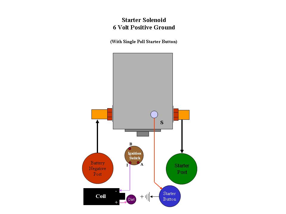
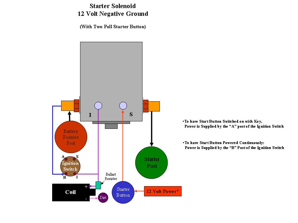
There are 3 posts on your 6 volt starter solenoid. Two big and one small. The small one runs to your Starter Button.
With the solenoid installed such that the button on the metal plate is pointing DOWN, as you look at the firewall of the truck, the left hand (on the trucks right side - pointing outward from the engine compartment) should have the 10 AWG wire that passes through the ammeter connected to it, and also the battery cable running up/back to the NEGATIVE Battery post.
Here's a picture of mine. It's a little hard to see and it looks as though I need to build a drawing of the Solenoid. But you can see the oreintation I'm describing. Also, mine is 12 volt and has a fourth post (that goes out to the ignition wire to the coil)
The other large post should have a cable that runs down to the starter connection (sticking out of the side of the starter)
#26
04-09-2010, 02:32 PM
Join Date: Nov 2007
Location: Western Mass
Posts: 109
Likes: 0
Received 0 Likes
on
0 Posts
Well I'm at it again, I just have one more connection to make than start up the truck and see if its charging.
O.K. the generator circuit is wired as per schematic and all the great help, truck starts right up and runs smoothly, ammeter reads like right in the middle. I can't tell if its charging though to be honest. Probably because I don't know how to read amps with my meter. Anyway, and sadly I have put my truck up for sale. Even as I continue to work on it a gentleman farmer and antiques dealer will be over to look at it in the next few days.
O.K. the generator circuit is wired as per schematic and all the great help, truck starts right up and runs smoothly, ammeter reads like right in the middle. I can't tell if its charging though to be honest. Probably because I don't know how to read amps with my meter. Anyway, and sadly I have put my truck up for sale. Even as I continue to work on it a gentleman farmer and antiques dealer will be over to look at it in the next few days.
Last edited by ricksta56; 04-09-2010 at 03:04 PM. Reason: more info
#27
04-10-2010, 01:08 AM
Post Fiend
Well, that's a shame. I hate to see someone sell their truck!
The dash ammeter should pop up a little when you start up the truck if yo have it wired in. Of course we don't know if the gauge is any good either. You can test it with a D-cell battery for the others who are interested. It will just move a dash if it's good.
Here's a picture of how, and here's also my two new drawings on Starter Solenoid hook ups I have a third one of these for a starter switch and no button in the gallery:
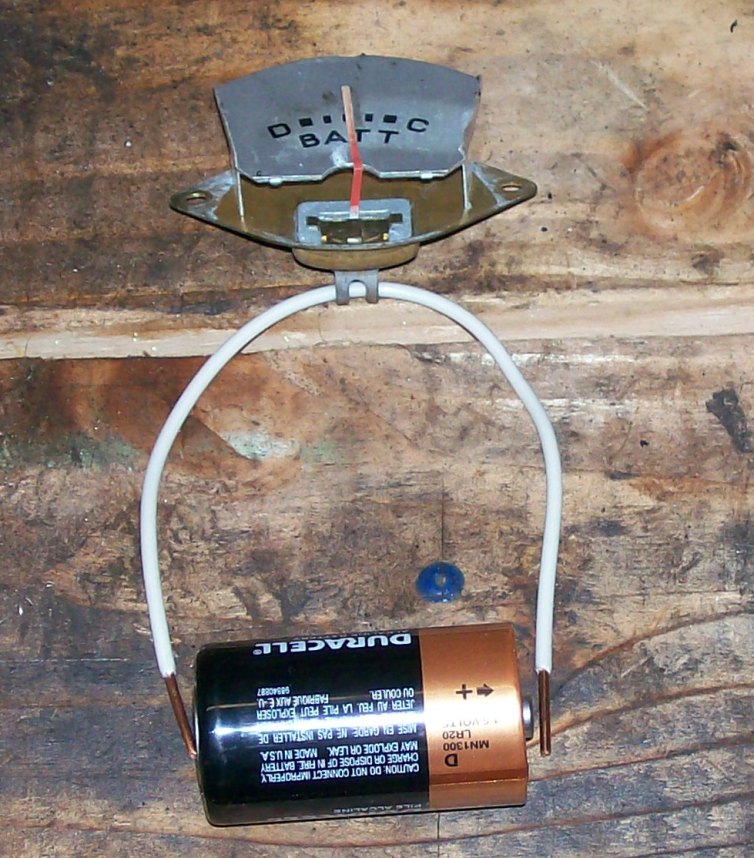

Thread
Thread Starter
Forum
Replies
Last Post
krustiy lusti
1948 - 1956 F1, F100 & Larger F-Series Trucks
7
04-14-2017 07:29 PM
Cougar54
1948 - 1956 F1, F100 & Larger F-Series Trucks
2
09-20-2015 09:30 PM
brucelee
1948 - 1956 F1, F100 & Larger F-Series Trucks
8
11-13-2010 02:04 PM

