


dual voltage electrical system

Thread Starter
|
Senior User
Joined: Jun 2008
Posts: 211
Likes: 0
From: Copperas Cove, TX
So I'm leaning towards the second alternator option now so I need to clarify some things.
1. Since the second alternator has to be isolated (and grounded to the 12V positive) what would be the best way to go about this? What I'm coming up with is that I would need to bascially make a rubber sleeve that would run through the mounting bracket AND the mounting holes of the second alternator; that way the bolt wouldn't be able to ground through.
2. To make the ground for the second alternator, would I need to drill into the casing at a non critical area (so it won't hit any revolving parts) and attatched a ground wire connecting to the 12V positive post?
3. To complete the 24V system the batteries would be wired in series (12V POS to batt #2 NEG) and then power wires would then be run from battery #2 POS to whatever accessories I choose?
4. The second alternator would be starting out as a 1 wire alternator. Since it can't be allowed to ground through the casing to the engine/bracket; is it now going to be a 2 wire alternator? Where does the first wire connect to?
Thanks for helping out so much ya'll. Some of my questions may seem odd, but I have lousy internet and some websites that I would gather my own info from just don't work so I have to ask them here. Again, thanks for bearing with me on this.
1. Since the second alternator has to be isolated (and grounded to the 12V positive) what would be the best way to go about this? What I'm coming up with is that I would need to bascially make a rubber sleeve that would run through the mounting bracket AND the mounting holes of the second alternator; that way the bolt wouldn't be able to ground through.
2. To make the ground for the second alternator, would I need to drill into the casing at a non critical area (so it won't hit any revolving parts) and attatched a ground wire connecting to the 12V positive post?
3. To complete the 24V system the batteries would be wired in series (12V POS to batt #2 NEG) and then power wires would then be run from battery #2 POS to whatever accessories I choose?
4. The second alternator would be starting out as a 1 wire alternator. Since it can't be allowed to ground through the casing to the engine/bracket; is it now going to be a 2 wire alternator? Where does the first wire connect to?
Thanks for helping out so much ya'll. Some of my questions may seem odd, but I have lousy internet and some websites that I would gather my own info from just don't work so I have to ask them here. Again, thanks for bearing with me on this.

Senior User
Joined: Jan 2004
Posts: 419
Likes: 0
From: Macomb, IL
Your diode between the batteries that goes to ground would be a dead short. The diodes between the BAT (Field) connection are wrong also. The BAT terminal energizes the Field coils in the ALT. You need power to flow to the Field. Let me see if I can find my picture of the correct wiring for a GM ALT.
Senior User
Joined: Jan 2004
Posts: 419
Likes: 0
From: Macomb, IL
Subford, your picture shows the 10-SI or 12-SI GM Alt. The bat terminal goes to battery and is used to energize the field, The larger wire on the connector goes to the rectifier pack and the small wire on the connector goes to 12V switched to energize the contraption <------OK I know this is a technical word and might confuse somebody  LOL
LOL
The light bulb can be replaced by a diode, and is required to keep the ALT from backfeeding the circuit with the power turned off. (Engine will continue to run after key is turned off.) The lamp is handy in that just like on a GM product, it lights when the ALT is not charging and can be used to monitor.
On a GM one wire ALT all these connections are made internally. No Fuss, no muss, at a substantial rise in cost. I have been putting these GM alternators on my externally regulated Ford since the early 1990's. Such a better design.

LOLThe light bulb can be replaced by a diode, and is required to keep the ALT from backfeeding the circuit with the power turned off. (Engine will continue to run after key is turned off.) The lamp is handy in that just like on a GM product, it lights when the ALT is not charging and can be used to monitor.
On a GM one wire ALT all these connections are made internally. No Fuss, no muss, at a substantial rise in cost. I have been putting these GM alternators on my externally regulated Ford since the early 1990's. Such a better design.
Senior User
Joined: Jan 2004
Posts: 419
Likes: 0
From: Macomb, IL
FTE Stories
Ford Trucks for Ford Truck Enthusiasts

Top 10 Most Expensive Ford Trucks Ever Sold on Bring a Trailer
Joe Kucinski
2027 Ford Super Duty Buyer's Guide (Every Model, Engine, & Package)
Brett Foote
Top 10 Ford Truck Tragedies
Joe Kucinski
AEV FXL Super Duty - the Super Duty Raptor Ford Doesn't Make
Brett Foote
Lobo Vs Lobo: Proof the F-150 Lobo Should Be Even Lower!
Michael S. Palmer
Ford's 2001 Explorer Sportsman Concept Looks For a New Home
Verdad Gallardo
10 Best Ford Truck Engines We Miss the Most!
Joe Kucinski
2026 Shelby F-150 Off-Road: Better Than a Raptor R?
Brett Foote
2027 Super Duty Carhartt Package First Look: 12 Things You NEED to Know!
Michael S. Palmer
Postmaster
Joined: Oct 2008
Posts: 3,026
Likes: 0
From: Renton, WA
1. Since the second alternator has to be isolated (and grounded to the 12V positive) what would be the best way to go about this? What I'm coming up with is that I would need to bascially make a rubber sleeve that would run through the mounting bracket AND the mounting holes of the second alternator; that way the bolt wouldn't be able to ground through.
I would do something like this for each place were bolt meats bracket.
Black = Rubber, Red = Bracket, Green = Bolt, Purple = Metal Washer, Blue = Alternator Body
---------------------------------------------------------
Subford, your drawing was more complicated then it needs to be, this is more correct. None of the diodes are needed, and the grounds for the second alt and between the batteries would be a short.
I added a switch to ground between the batteries to show one of the big advantages of a system like this for a truck. Switching the second battery from BAT #1 POS to Ground makes the second Battery and Alternator an isolated backup or auxilary 12v system. You can jump start yourself, or use it as a deep cycle for acc without draining the primary bat. There's all kinds of goodness from a system like this with some clever wiring.
Senior User
Joined: Jan 2004
Posts: 419
Likes: 0
From: Macomb, IL
I smell smoke real well now.......
Rubber will deform under the pressure and fail.
A diode, in this case a heavy duty rectifier (another name for diode, but heavy duty) would be necessary to prevent back flow from occurring between the 2 systems.
It is still a heck of allot cheaper and easier to buy some new lights.
Less fire potential as well.
Rubber will deform under the pressure and fail.
A diode, in this case a heavy duty rectifier (another name for diode, but heavy duty) would be necessary to prevent back flow from occurring between the 2 systems.
It is still a heck of allot cheaper and easier to buy some new lights.
Less fire potential as well.
Postmaster
Joined: Oct 2008
Posts: 3,026
Likes: 0
From: Renton, WA
No, diodes/rectifiers are needed, not sure why you think so. But the alternators already have rectifiers in them (3 diodes), that's what makes them alternators, and not generators. Without the rectifiers they would be 3 phase AC generators.
Postmaster
Joined: Oct 2008
Posts: 3,026
Likes: 0
From: Renton, WA
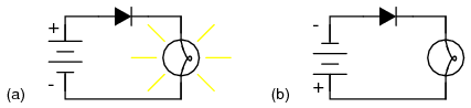
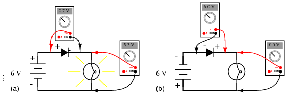
Subford and kc0rey, you two got into this current frow argument. Here's my addition to the agrument. And this whole which way current flows argument doesn't matter and is something electrical engineers have been arguing over for a long time.


Fleet Owner


Joined: Aug 2005
Posts: 23,667
Likes: 301
From: Easton,Ks
Your drawings say that the current does flow against the arrows.
Current flows from negative to positive as there is an excess of electrons on the negative plate and they will do what ever they can to get to the positive side of the battery. That is why the lamp is on in "A".
By the way I did work as an Electronics Technician for 10 years and another 10 years supervising a group Electronics Technicians. Started out working on main frame computers and their interface to sensors and solenoids but at the end were using MicroComputers. Did a lot of board level repair so I think I know how current flows through a diode.
Current flows from negative to positive as there is an excess of electrons on the negative plate and they will do what ever they can to get to the positive side of the battery. That is why the lamp is on in "A".
By the way I did work as an Electronics Technician for 10 years and another 10 years supervising a group Electronics Technicians. Started out working on main frame computers and their interface to sensors and solenoids but at the end were using MicroComputers. Did a lot of board level repair so I think I know how current flows through a diode.
Thread Starter
|
Senior User
Joined: Jun 2008
Posts: 211
Likes: 0
From: Copperas Cove, TX
I am base out of Ft. Lewis, but I own my home in Tacoma and will be returning there after deployment. My truck that all this discussion is for is at my house in Tacoma as well.