TFI to Duraspark II conversion help needed

Post Fiend
Joined: Jul 2004
Posts: 8,786
Likes: 28
From: Northern California
I rechecked my Ford Service manual.
The range is 6-8 volts engine NOT running, using their test proceedure. With the connector at the coil disconnected, using a voltmeter. This would cause flow of current also as battery flow went through the resistor, through the wires through the voltmeter to ground.
So 10 volts with engine RUNNING should be fine, as the charging system will raise the system voltage from aproximately 12 to 14 volts.
Sorry about that confusion.
Cargo Master


Joined: Mar 2008
Posts: 2,573
Likes: 207
From: Washington
coil photo
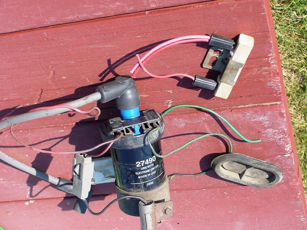
This is a photo of an Electronic ignition coil that was used in a DS2 system that I got at the junk yard. It is marked �use with electronic ignition� and �made in USA�. It also has a blue top.
I also have a new in the box coil that has P/N�s on the box which indicates it is for a Duraspark system, but the coil is painted glossy black with no markings on it all on it.
You might not have the right coil� or to say the one you got at the junk yard might not be for electronic ignition. I really don�t now, just throwing out ideas to think about. The fact that the coil is running hot is still worrying me a little, but it could also just be a normal thing for the coil to be warmer. It might not be a bad idea to pick up a spare coil to try and maybe even a DS2 module at the junk yard to carry under the seat as a spare until you get that warm fuzzy feeling that your truck is reliable and trust worthy again.
Also shown in the photo is the rubber plug to go in the firewall hole, were all the computer wiring went. Look for one of these while at the junk yard for a clean stock looking installation.
Jim

Thread Starter
|
New User
Joined: Sep 2009
Posts: 19
Likes: 0
Maybe I'm too nervous but I'm often far enough back that walking home is not an option. The coil I pulled was hooked up to the DSII(I got the whole package Carb and all electronic parts out of same rig) module. With my old TFI I kept a spare module in my repair kit(nightmares from past TFIs).
My Haynes manual shows a R-LG from run to 1.05 resistor and a br-pk from start that splice back together. So where is the large red yellow striped wire coming from and why do the resistor and br-pk splice together with it?
I peeled the wire bundle back to the firewall and ran a meter probe into the smaller red wire and got 6-8 v near the splice and 10 v near firewall. With the three wires separated, it now becomes apparent that the thin red wire very thin yellow or green stripe is a resistor wire as it is the one that becomes warm to touch with ignition switch in on position. The thicker red with yellow or light green stripe comes from firewall, splices into the brown/pink and small red and then continues out to a female fitting that matches my DS2 coil male. I don�t see how the coil will be receiving reduced voltage if the resistor line is spliced back into the thick red line. Do I need to cut the resistor and Brown wires and connect them direct to the coil going around the plug to avoid the thick red wire?
Nice powerpoint slide here but can't get it to paste
<?xml:namespace prefix = v ns = "urn:schemas-microsoft-com:vml" /><v:shapetype id=_x0000_t75 stroked="f" filled="f" path="m@4@5l@4@11@9@11@9@5xe" o referrelative="t" o:spt="75" coordsize="21600,21600"><v:stroke joinstyle="miter"></v:stroke><v:formulas><v:f eqn="if lineDrawn pixelLineWidth 0"></v:f><v:f eqn="sum @0 1 0"></v:f><v:f eqn="sum 0 0 @1"></v:f><v:f eqn="prod @2 1 2"></v:f><v:f eqn="prod @3 21600 pixelWidth"></v:f><v:f eqn="prod @3 21600 pixelHeight"></v:f><v:f eqn="sum @0 0 1"></v:f><v:f eqn="prod @6 1 2"></v:f><v:f eqn="prod @7 21600 pixelWidth"></v:f><v:f eqn="sum @8 21600 0"></v:f><v:f eqn="prod @7 21600 pixelHeight"></v:f><v:f eqn="sum @10 21600 0"></v:f></v:formulas><vath o:connecttype="rect" gradientshapeok="t" o:extrusionok="f"></vath><?xml:namespace prefix = o ns = "urn:schemas-microsoft-com
 fficeffice" /><o:lock aspectratio="t" v:ext="edit"></o:lock></v:shapetype><v:shape id=_x0000_i1025 style="WIDTH: 459.6pt; HEIGHT: 370.2pt" type="#_x0000_t75"><v:imagedata o:title="wires" src="file:///C:\DOCUME~1\thorpej\LOCALS~1\Temp\msohtml1\01\clip _image001.jpg"></v:imagedata></v:shape><o></o>
As far as coils go, I have removed the square tfi and mounted the round DS2 coil but I still have connectors and brackets for both. That was why I asked if a solution for coil survival might be to just keep using the tfi coil.
<o></o>
The reason for this swap is based on history. I had two different 1981 Ford F-150 govt rigs while working in <?xml:namespace prefix = st1 ns = "urn:schemas-microsoft-comffice:smarttags" /><st1:State><st1lace>Idaho</st1lace></st1:State> and ran several hundred thousand bullet proof flawless miles (finally forced by hdqtrs to replace them) and also had an 84 and 85 that we could simply never keep running and sent back to auction as soon as possible. It wasn�t until I bought this carbureted 1986(hwy miles and clean truck) that I started researching that I learned the subtle differences that occurred in 1984. This truck ran quite well for a little over a year ave 18mpg on hwy and very dependable. Then I had a cracked ring started blowing oil all over and had a remanufactured engine installed last summer(carb rebuilt, new sensors, flywheel etc). For the last year nothing but trouble- couldn�t get idle under control, backfires, 10-12 mpg, randomly goes dead and generally very difficult to operate. Finally put it in a smoke room this spring and determined that first off the carburetor was sucking air all over the place. My decision �rather than spend a fortune on a new feedback carburetor and hope that there were no electronic gremlins haunting the engine�I would go back to the simple dependable ignition and carburetor that I could diagnose and repair without another computer.
My Haynes manual shows a R-LG from run to 1.05 resistor and a br-pk from start that splice back together. So where is the large red yellow striped wire coming from and why do the resistor and br-pk splice together with it?
I peeled the wire bundle back to the firewall and ran a meter probe into the smaller red wire and got 6-8 v near the splice and 10 v near firewall. With the three wires separated, it now becomes apparent that the thin red wire very thin yellow or green stripe is a resistor wire as it is the one that becomes warm to touch with ignition switch in on position. The thicker red with yellow or light green stripe comes from firewall, splices into the brown/pink and small red and then continues out to a female fitting that matches my DS2 coil male. I don�t see how the coil will be receiving reduced voltage if the resistor line is spliced back into the thick red line. Do I need to cut the resistor and Brown wires and connect them direct to the coil going around the plug to avoid the thick red wire?
Nice powerpoint slide here but can't get it to paste
<?xml:namespace prefix = v ns = "urn:schemas-microsoft-com:vml" /><v:shapetype id=_x0000_t75 stroked="f" filled="f" path="m@4@5l@4@11@9@11@9@5xe" o
referrelative="t" o:spt="75" coordsize="21600,21600"><v:stroke joinstyle="miter"></v:stroke><v:formulas><v:f eqn="if lineDrawn pixelLineWidth 0"></v:f><v:f eqn="sum @0 1 0"></v:f><v:f eqn="sum 0 0 @1"></v:f><v:f eqn="prod @2 1 2"></v:f><v:f eqn="prod @3 21600 pixelWidth"></v:f><v:f eqn="prod @3 21600 pixelHeight"></v:f><v:f eqn="sum @0 0 1"></v:f><v:f eqn="prod @6 1 2"></v:f><v:f eqn="prod @7 21600 pixelWidth"></v:f><v:f eqn="sum @8 21600 0"></v:f><v:f eqn="prod @7 21600 pixelHeight"></v:f><v:f eqn="sum @10 21600 0"></v:f></v:formulas><vath o:connecttype="rect" gradientshapeok="t" o:extrusionok="f"></vath><?xml:namespace prefix = o ns = "urn:schemas-microsoft-comfficeffice" /><o:lock aspectratio="t" v:ext="edit"></o:lock></v:shapetype><v:shape id=_x0000_i1025 style="WIDTH: 459.6pt; HEIGHT: 370.2pt" type="#_x0000_t75"><v:imagedata o:title="wires" src="file:///C:\DOCUME~1\thorpej\LOCALS~1\Temp\msohtml1\01\clip _image001.jpg"></v:imagedata></v:shape><o></o>As far as coils go, I have removed the square tfi and mounted the round DS2 coil but I still have connectors and brackets for both. That was why I asked if a solution for coil survival might be to just keep using the tfi coil.
<o
></o>The reason for this swap is based on history. I had two different 1981 Ford F-150 govt rigs while working in <?xml:namespace prefix = st1 ns = "urn:schemas-microsoft-com
ffice:smarttags" /><st1:State><st1lace>Idaho</st1lace></st1:State> and ran several hundred thousand bullet proof flawless miles (finally forced by hdqtrs to replace them) and also had an 84 and 85 that we could simply never keep running and sent back to auction as soon as possible. It wasn�t until I bought this carbureted 1986(hwy miles and clean truck) that I started researching that I learned the subtle differences that occurred in 1984. This truck ran quite well for a little over a year ave 18mpg on hwy and very dependable. Then I had a cracked ring started blowing oil all over and had a remanufactured engine installed last summer(carb rebuilt, new sensors, flywheel etc). For the last year nothing but trouble- couldn�t get idle under control, backfires, 10-12 mpg, randomly goes dead and generally very difficult to operate. Finally put it in a smoke room this spring and determined that first off the carburetor was sucking air all over the place. My decision �rather than spend a fortune on a new feedback carburetor and hope that there were no electronic gremlins haunting the engine�I would go back to the simple dependable ignition and carburetor that I could diagnose and repair without another computer.
Cargo Master
Joined: Mar 2008
Posts: 2,573
Likes: 207
From: Washington
when I say extra 3rd wire I mean this one... "So where is the large red yellow striped wire coming from and why do the resistor and br-pk splice together with it?"
The extra 3rd wire seems to be the souce of the higher voltage.
Post Fiend
Joined: Jul 2004
Posts: 8,786
Likes: 28
From: Northern California
Is the 3rd wire Red/Lt. Green or Red/Yellow? That is important as these are two different circuts, but they do connect.
The Brown/Pink wire is the Start Bypass, it goes to the ignition switch and supplies full voltage in start mode only. It's meant to bypass the Resistor wire but only in start.
The Smaller Red/Lt. Green wire is the Resistor.
The other larger Red/Lt. Green wire should be the wire that goes to the coil.
Please confirm this, as this is how it's supposed to be wired, confirmed by the Ford wiring diagrams.
Another idea...
How old is the coil? The coil is full of oil. The oil in the coil is what keeps it cool. It can deteriorate over time causing the coil to run hotter untill it fails.
I'll see if I have the wiring diagrams scanned and post them. They may help.
Post Fiend
Joined: Jul 2004
Posts: 8,786
Likes: 28
From: Northern California
Here are the diagrams
Power Distrubution:
http://s447.photobucket.com/albums/q...t=scan0010.jpg
Charge Start and Run DS-II system:
http://s447.photobucket.com/albums/q...t=scan0011.jpg
Power Distrubution:
http://s447.photobucket.com/albums/q...t=scan0010.jpg
Charge Start and Run DS-II system:
http://s447.photobucket.com/albums/q...t=scan0011.jpg
Thread Starter
|
New User
Joined: Sep 2009
Posts: 19
Likes: 0
I had thought about cutting the large red with Yellow? stripe and then the bn-pk and red resistor wire would be the only ones going out to the coil. I haven't tried that yet -I just thought of it this morning. If that's correct I'm wondering why the bn-pk red resistor are onded into the red and yellow before there travel out to the connector plug.
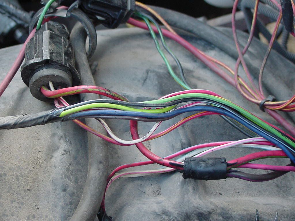
Next- the coil came out of a junked 1981 1/2 ton. I wish i could post the powerpt slide I created this morning-oh well. I ran the voltage difference test last night on the small red wire that got warm.There are three wires bonded at a splices 6" or so above the plug connector that matched my DS2 plug with wires leading to coil, water and oil sensor. The three wires are a large 3/16 to 1/4" brown-pink stripe wire, a large 3/16 to 1/4" red with yellow stripe and a much smaller(14 gauge?) red with almost invisible yellow or light green stripe. What comes out of the splice is the same large red with yellow stripe wire which is one that goes into a four slot female plug. The large wire matches the pin coming from the coil via s small red wire.
The brn-pk and resistor make sense I just can't figure the larger red-yellow wire , both where it's coming from amd why it's needed if I'm getting the reduced run voltage out of the small red wire from ignition.
Post Fiend
Joined: Jul 2004
Posts: 8,786
Likes: 28
From: Northern California
It should have Three wires yes. Two Red/Lt. Green wires, and one Brown/Pink wire.
One Red/Lt Green is the resistor coming from the ignition switch.
Another Red/Lt. Green wire to the coil. Because the resistor changes to a regular wire at the splice.
And the Brown/Pink Start Bypass wire.
So if there is another Red/Yellow wire, this could be the problem.
FTE Stories
Ford Trucks for Ford Truck Enthusiasts

10 Ugly Ford Trucks That We Still Kinda Love
Joe Kucinski
10 Things Every Truck Owner NEEDS (2026 Edition)
Michael S. Palmer
Rezvani's Latest Post-Apocalyptic Monster Is a Ford F-150 Raptor Underneath
Verdad Gallardo
Top 10 Most Expensive Ford Trucks Ever Sold on Bring a Trailer
Joe Kucinski
2027 Ford Super Duty Buyer's Guide (Every Model, Engine, & Package)
Brett Foote
Top 10 Ford Truck Tragedies
Joe Kucinski
AEV FXL Super Duty - the Super Duty Raptor Ford Doesn't Make
Brett Foote
Lobo Vs Lobo: Proof the F-150 Lobo Should Be Even Lower!
Michael S. Palmer
Ford's 2001 Explorer Sportsman Concept Looks For a New Home
Verdad Gallardo
Thread Starter
|
New User
Joined: Sep 2009
Posts: 19
Likes: 0
I went back and traced the original tfi system wiring from the plug connection(mates to large red with yellow stripe wire) that seemed to supply(and does in the DS2 harness) the tfi coil with power. It was a brown wire leaving the plug but ran out into wire bundle and was spliced to three other wires, one of which ran to the tfi coil. Maybe the thick red-y wire that has bypass and resistor wire spliced into it was intended to deliver full voltage to some other systems(hence the multi-wire splice later on).
81-F-150-Explorer ---You're right the wire I'm talking about is not on the wiring diagrams. I've been looking at the same map you sent for quite some time now(it's in the Haynes manual) and can't figure what the big red wire is or where it comes from.
JimsRebel-- I think that I will at some point try jumping around the plug directly into the coil wire and take the large red wire that everything is spliced into- before I just cut it. I think that If I cut that wire then the bypass and resistor wires would be the spliced at the rubber splice above the plug and then flow to coil. I should get reduced volts at run and full through the bypass at start.
The immediate course I'm taking is put the old tfi coil back in place. I'll cut the green and red wires that now feed my DS2 coil through the duraspark harness and splice into the tfi coil connector. I know that the tfi coil ran fine in the line voltage that I'm seeing now so I won't damage the tfi coil. Then as time allows I'll try testing the two wires(bypass and resistor) only mode for the 6-8 reduced voltage in the coil line at run.
The thick red and yellow wire remains a mystery and will require that I chase it through the firewall and unwrap all the wires under the dash. At least it's so big I won't have trouble identifying it when I reach the source.
Thanks Much
Cargo Master
Joined: Mar 2008
Posts: 2,573
Likes: 207
From: Washington
Jim
Thread Starter
|
New User
Joined: Sep 2009
Posts: 19
Likes: 0
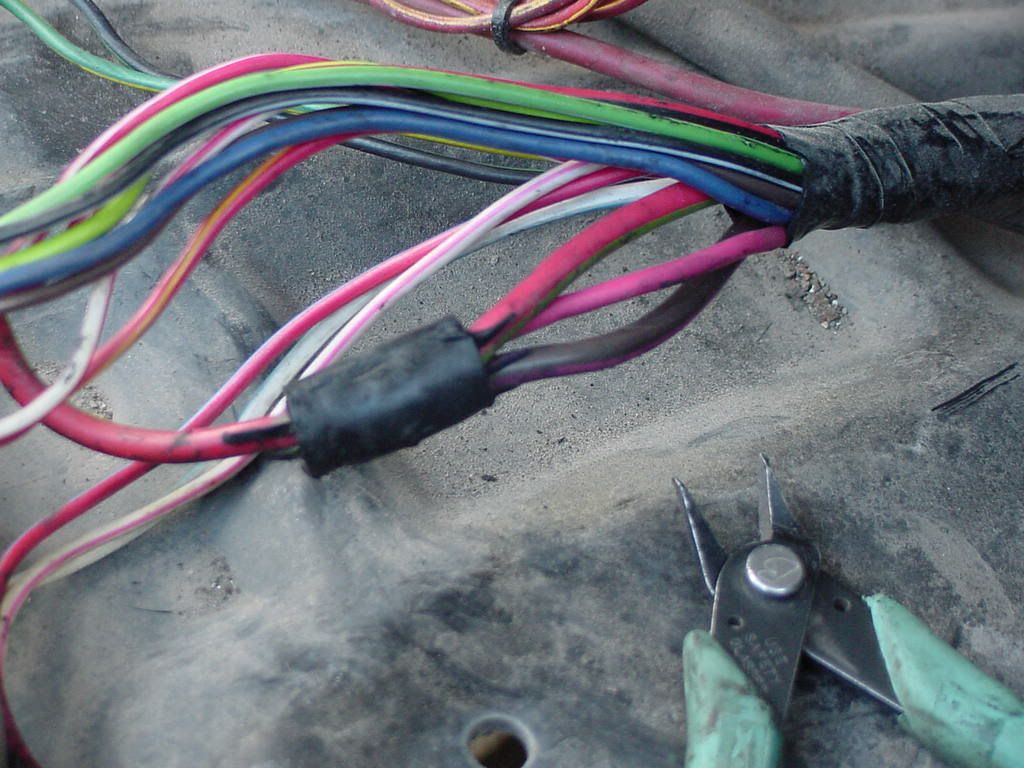
I certainly can do that. My choices were to try some jumpers I have made of 12g wire soldered to safety pins for coupling mismatch trailer wiring and go around the plug or----or reach for the dykes and snip the mystery wires. Doesn't your 1986 have the same thick red with yellow stripe wire running into the four wire plug with the oil and water sensor lines?
Thread Starter
|
New User
Joined: Sep 2009
Posts: 19
Likes: 0
JimsRebel----
I've been trying to put in a picture of my wiring without success. Fortunately, I was running through the Randy2631 thread where he was bouncing from DS@ to HEI. You sent me that link on 9-27-2009. In frame #15 posted by Randy2631 on 8-3-2009 at 8:31PM of that link there is a picture of the wiring laying on the fender. That is exactly what I have. You can see the three wires joining at a large rubber connector then the thick red-yellow wire leads to the plug. I notice that he is using a tfi coil not the ds2. How do I reach him? He swapped to the DS2 coil-I wonder what his voltage readings were?
I've been trying to put in a picture of my wiring without success. Fortunately, I was running through the Randy2631 thread where he was bouncing from DS@ to HEI. You sent me that link on 9-27-2009. In frame #15 posted by Randy2631 on 8-3-2009 at 8:31PM of that link there is a picture of the wiring laying on the fender. That is exactly what I have. You can see the three wires joining at a large rubber connector then the thick red-yellow wire leads to the plug. I notice that he is using a tfi coil not the ds2. How do I reach him? He swapped to the DS2 coil-I wonder what his voltage readings were?

Cargo Master
Joined: Mar 2008
Posts: 2,573
Likes: 207
From: Washington
The link is in post #15 of this thread,
He is right... the photo shows 3 in and 1 wire out. I might have to see if my truck also has this.