
fuel pump relay wiring


Thread Starter
|
New User
Joined: Feb 2009
Posts: 14
Likes: 0
fuel pump relay wiring
Ok, I am trying to get my 88 f250 351w running again. For whatever reason, the wiring going to the front fuel pump got shorted out and melted wires together from the pump all the way to the tank switch in the cab, and out to the relay. Now I have most of it straightened out, however, I am having trouble getting my mind wrapped around this whole deal. Here is my situation.
The yellow wire at the relay (supposed to be always hot) has 12 volts at all times, as it supposed to.
The red and tan/light green wires get 12 volts when key is turned on, best I can tell this is what is supposed to pull the relay in and hence put power to the brown wire which should go the the inertia switch, then on to the tank switch and power the pumps. Now to my dilemma, when the key is turned on, there is only 7 volts to the brown wire, not 12 as I expected.
NOw am I just crazy, confused or is this the way it is supposed to be?
Btw, I put a new relay in and same results.

Posting Guru
Joined: Jan 2002
Posts: 1,346
Likes: 8
From: Baltimore
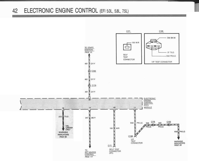
When you turn the ignition to ON, the computer should ground the Tan/Light Green wire which will close the fuel pump relay for 1 second.
If the ignition switch is in the START (engine cranking) position the computer will keep the fuel pump relay energized as long as it sees reference pulses coming from the distributor. As you release the key to the ON position
and the engine is running, the computer will continue to ground the Tan/Light Green wire which will keep the fuel pump relay energized providing 12 volts to the High pressure pump on the frame rail and the selected in tank pump.
You can test the fuel pump relay and fuel pump circuit by turning the ignition to ON and manually grounding the Tan/Light Green wire.
There is also a VIP test connector located towards the back of the black plastic driver side wheel well housing. It's the test connector where you can attach a code reader to pull engine codes. The second schematic shows the connector in the top right corner. The Tan/Light Green wire also goes to this connector so you can ground the wire there which should close the fuel pump relay.
Thread Starter
|
New User
Joined: Feb 2009
Posts: 14
Likes: 0
Thank you very much. I believe that is the explanation that I was looking for. Hopefully I can go home this evening and get this lined out.
Where do you get these detailed schematics, the ones in my cheap chilton are quite vague and I have found that some of the wire colors are incorrect. I need to get ahold of something like that, more detailed and accurate.
Am I correct in my thinking that if I ground the t/lg wire, the brown wire should then get 12 volts?
Thanks, Derek
Posting Guru
Joined: Jan 2002
Posts: 1,346
Likes: 8
From: Baltimore
The schematics come from Helms who is the publisher for the Ford factory service manuals. There are a bunch of different manuals. If you were to purchase all of them they would cost over $150. http://www.helminc.com
Yes the relay should close and 12 volts from the Yellow wire should provide the Brown wire with the 12 volts. If the wires melted from one of the in tank pumps back to the relay, I'd say either that in tank pump is bad (shorted motor windings, the motor is seized) or there is a wiring problem in the harness causing the wire to heat up but its not drawing enough current to blow the fusible link which protects the Yellow wire.
The 7 volts you measured on the Tan/Light Green wire is coming from the computer. When the computer energizes the fuel pump relay, you should measure zero volts on the Tan/Light Green wire.
The 7 volts you measured on the Tan/Light Green wire is coming from the computer. When the computer energizes the fuel pump relay, you should measure zero volts on the Tan/Light Green wire.
Thread Starter
|
New User
Joined: Feb 2009
Posts: 14
Likes: 0
I went to the Helm site, I was going to order the wiring diagrams manual, but it is out of stock.
Thanks again for the info. I am an auto mechanic part-time, I work on about everything, but for some reason this truck is driving me crazy. I guess because it is my own and I am not getting paid to work on it. LOL
I keep resisting the temptation of tearing all of the wiring and injection off and putting the pumps on a toggle and throwing a carb and hei on it. I am just not ready to give up yet, I know with a little help I can whop this thing into submission.

New User
Joined: May 2009
Posts: 2
Likes: 0
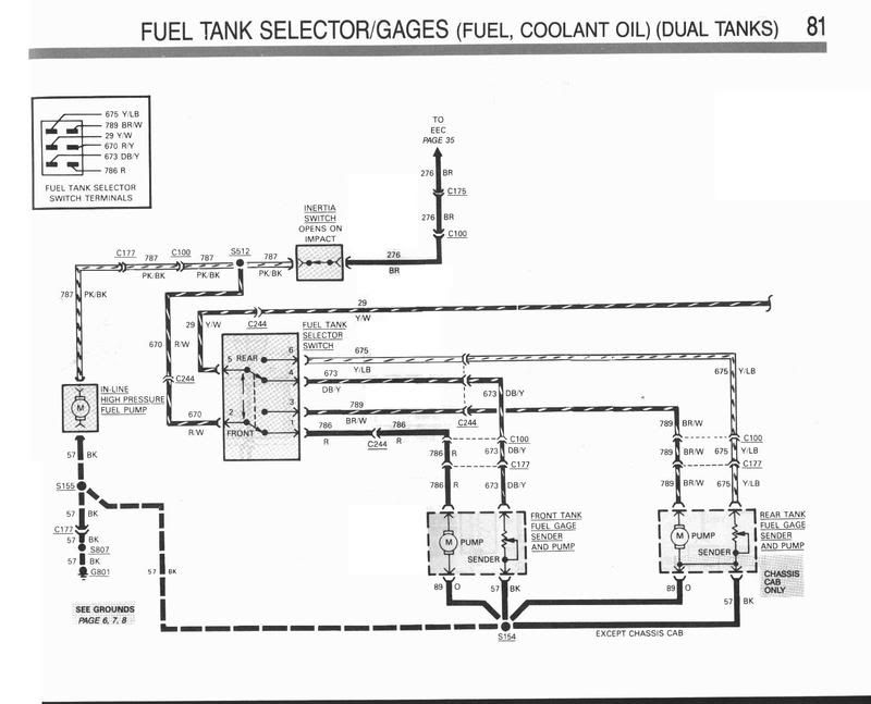
Are these schematic diagrams valid for 1990 F250 460 V8 (7.5L EFI) AT/OD? My truck runs off the front tank, but the fuel gauge does not work. When I switch to the rear tank the engine quits but the gauge shows 1/4 tank. Today is my first day on this forum and I acquired the truck on Tuesday. It has approx 221k and does not smoke and got 16 mpg on the highway from Ennis, TX to Madisonville, TX. I immediately changed the oil before taking to the highway as the oil looked like oil in my 86 diesel 4x4 suburban.
Fleet Owner


Joined: Aug 2005
Posts: 23,667
Likes: 301
From: Easton,Ks
Are these schematic diagrams valid for 1990 F250 460 V8 (7.5L EFI) AT/OD? My truck runs off the front tank, but the fuel gauge does not work. When I switch to the rear tank the engine quits but the gauge shows 1/4 tank. Today is my first day on this forum and I acquired the truck on Tuesday. It has approx 221k and does not smoke and got 16 mpg on the highway from Ennis, TX to Madisonville, TX. I immediately changed the oil before taking to the highway as the oil looked like oil in my 86 diesel 4x4 suburban.
The FDM with the pump inside of it that is inside your rear tank is more than likely bad.

Thread
Thread Starter
Forum
Replies
Last Post
Dillweed73
1987 - 1996 F150 & Larger F-Series Trucks
6
Mar 8, 2017 09:12 PM
Catchog
1987 - 1996 F150 & Larger F-Series Trucks
15
Apr 14, 2016 03:44 PM
dakota-boy
Electrical Systems/Wiring
10
Mar 14, 2016 09:29 AM
shane733
Explorer, Sport Trac, Mountaineer & Aviator
2
Apr 5, 2004 04:21 PM


