


New '47 COE idea
Thread Starter
|
More Turbo
Joined: Jan 2007
Posts: 593
Likes: 15
From: Wichita, KS
Okay, I moved the pics from one folder in my Photobucket account to another, but I'm not able to edit the previous posts, so here are the links to the pics that were there.
http://i97.photobucket.com/albums/l2...DSCN6551cs.jpg
http://i97.photobucket.com/albums/l2...DSCN6553cs.jpg
http://i97.photobucket.com/albums/l2...DSCN6552cs.jpg
http://i97.photobucket.com/albums/l2...DSCN6554sm.jpg
http://i97.photobucket.com/albums/l2...DSCN6557sm.jpg
http://i97.photobucket.com/albums/l2...DSCN6558sm.jpg
http://i97.photobucket.com/albums/l2...DSCN6559cs.jpg
Sorry.
Dave
Thread Starter
|
More Turbo
Joined: Jan 2007
Posts: 593
Likes: 15
From: Wichita, KS
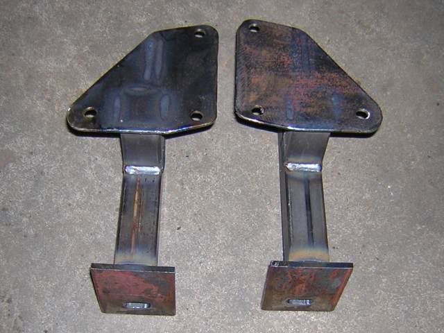
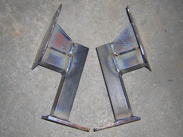
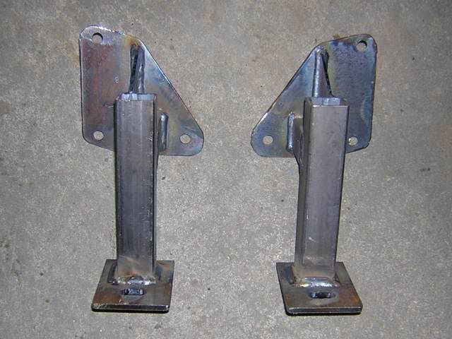
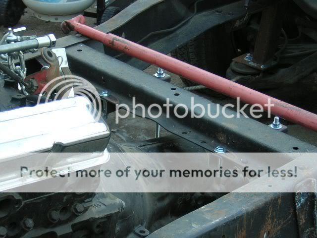
I was able to make a little more progress on getting the motor mounted in the temporary frame. I don't know why I have to make stuff so difficult. I could just weld a piece of tubing across the frame and be done with it, but no, I have to go and make bolt in brackets in case I want to do something different or need to make adjustments. Argh! Anyway, here are the brackets ready to be bolted in.
Dave
Dave
Thread Starter
|
More Turbo
Joined: Jan 2007
Posts: 593
Likes: 15
From: Wichita, KS
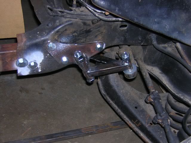
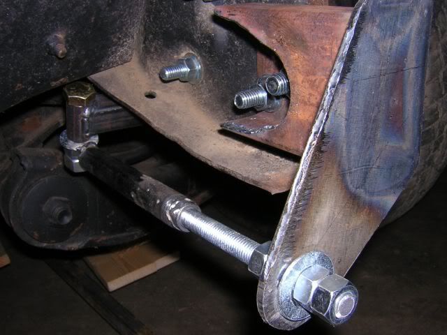
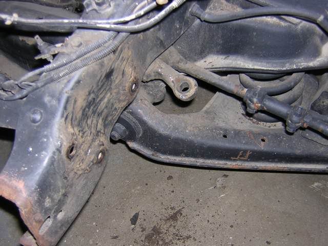
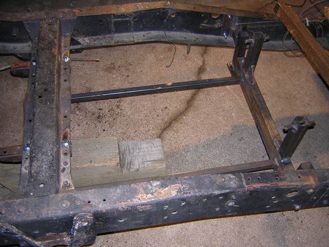
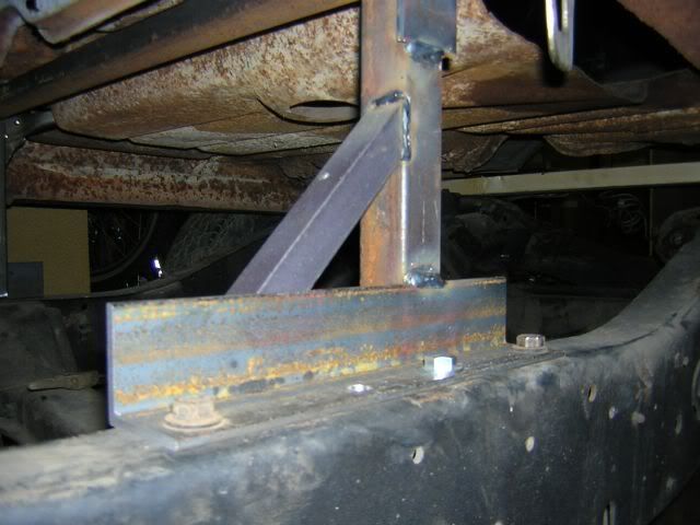
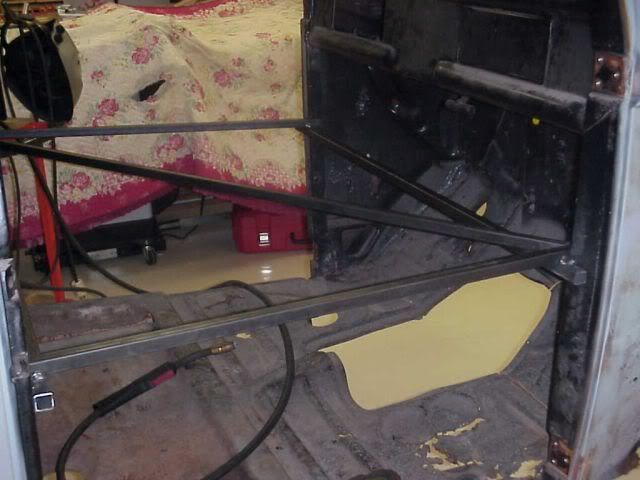
I also pulled the steering box off the frame as it was in the way, and it made steering the truck more difficult. But I still need to be able to control the truck, so I made a new arm and am working on a leadscrew arrangement to allow me to steer the truck. Should be pretty neat when it's done.
Here is where the steering box used to be.
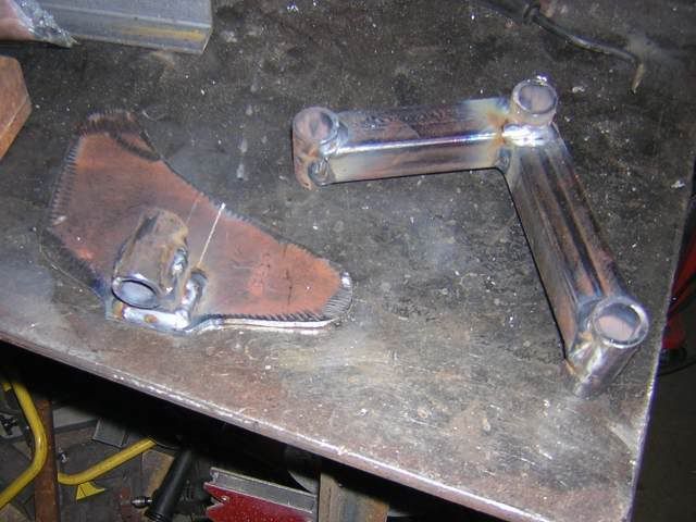
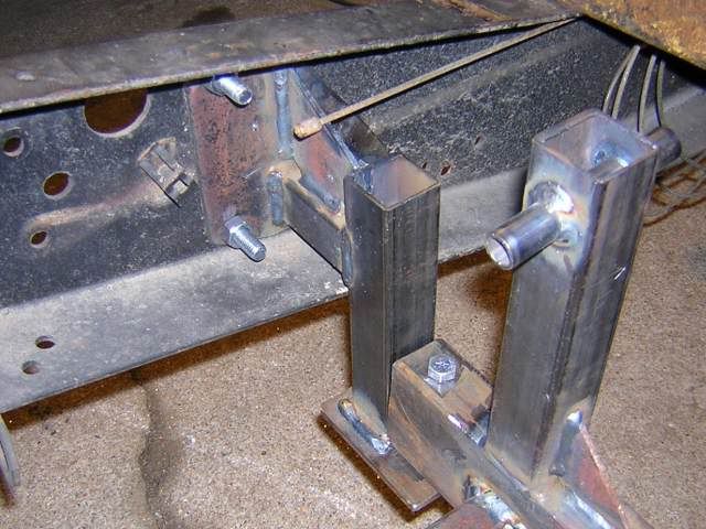
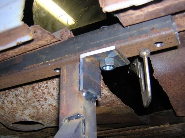
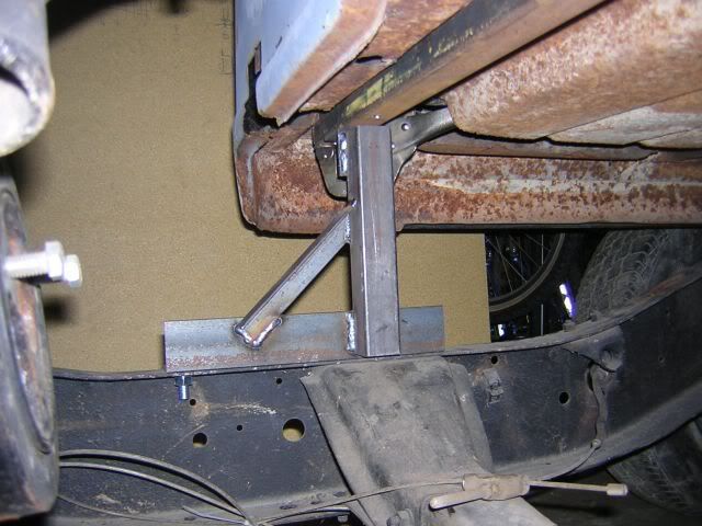
This is the start of the new temporary steering.
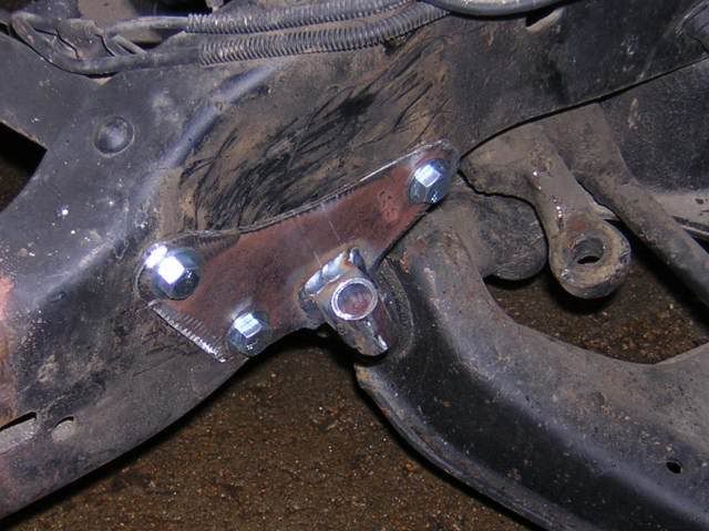
This is the bracket for the steering arm bolted in place.
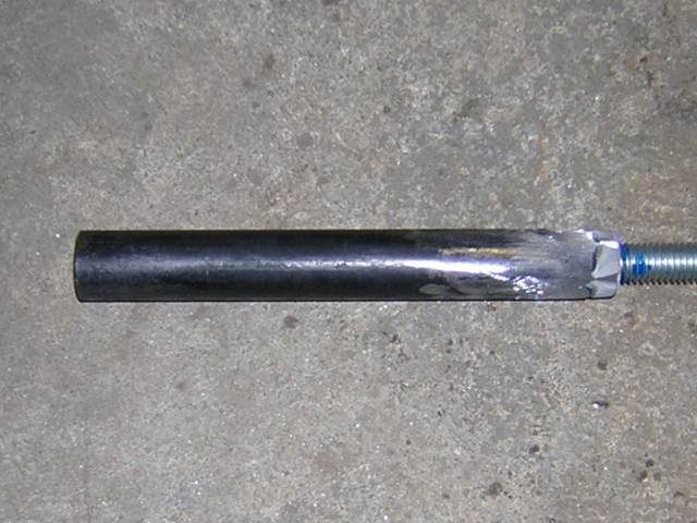
This will be the leadscrew for the temporary steering when it's done.
Dave
Here is where the steering box used to be.
This is the start of the new temporary steering.
This is the bracket for the steering arm bolted in place.
This will be the leadscrew for the temporary steering when it's done.
Dave
Thread Starter
|
More Turbo
Joined: Jan 2007
Posts: 593
Likes: 15
From: Wichita, KS
Engine temporarily mounted
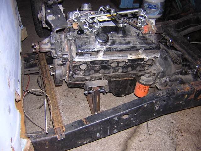
I was able to get the engine placed in the frame. It's not quite where I want it, but it's close. I actually need to go about an inch lower since I put taller tires on the front. But it tells me what I need to know.
This is the engine cradle in place in the frame.
Here are the front mounts with the engine cradle resting in place.
A couple of pieces of all-thread will hold the rear up. For now I welded some bolts to the end of some 3/8" bar, but I don't have enough adjustability with that arrangement, so I'll have to change that.
Dave
Thread Starter
|
More Turbo
Joined: Jan 2007
Posts: 593
Likes: 15
From: Wichita, KS
Here it is with the engine.
The underside is about an inch further from the ground than I had planned. This was a tire issue. But I can make some changes and lower the engine an inch to get the desired effect.
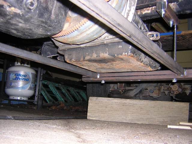
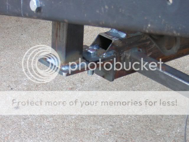
I hadn't planned on this little issue. I am up against this crossmember. When I measured I apparently was measuring too far back on the transmission, so I thought I had more clearance. Turns out I didn't. When I lower the rear of the transmission, this problem will go away.
Overall, I'm pretty happy with the progress so far. I need to get the floor of the cab figured out between now and the 26th, but with the help of some other folks here, I don't think that'll be a problem. Then I can get more into the sheetmetal and frame construction.
Dave
The underside is about an inch further from the ground than I had planned. This was a tire issue. But I can make some changes and lower the engine an inch to get the desired effect.
I hadn't planned on this little issue. I am up against this crossmember. When I measured I apparently was measuring too far back on the transmission, so I thought I had more clearance. Turns out I didn't. When I lower the rear of the transmission, this problem will go away.
Overall, I'm pretty happy with the progress so far. I need to get the floor of the cab figured out between now and the 26th, but with the help of some other folks here, I don't think that'll be a problem. Then I can get more into the sheetmetal and frame construction.
Dave
Thread Starter
|
More Turbo
Joined: Jan 2007
Posts: 593
Likes: 15
From: Wichita, KS
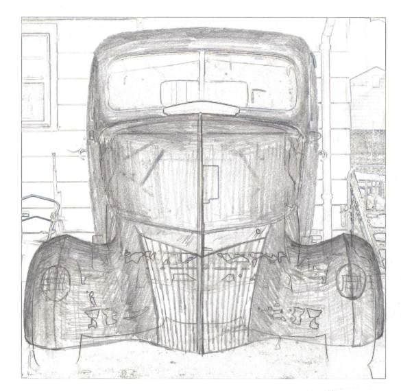
Just thought I'd toss a sketch of the front view as I have envisioned it up here. The fronts of the fenders will extend down a little further and may rise a little more, to allow for suspension movement. So, it's not quite correct yet, but it's a start.
Dave
Dave
Thread Starter
|
More Turbo
Joined: Jan 2007
Posts: 593
Likes: 15
From: Wichita, KS
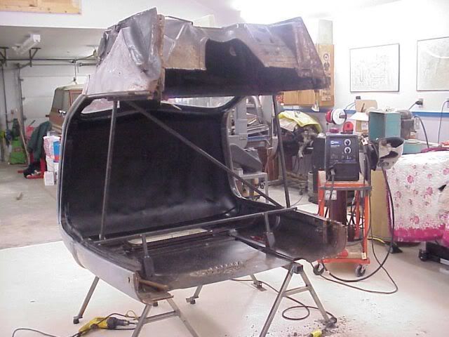
And the cab is more securely attached to the temporary frame. I no longer have it sitting on a 2x4 with wooden blocks relying on gravity to keep it in place, but not any lower. I used to have to worry about it sliding around. It doesn't slide anymore.
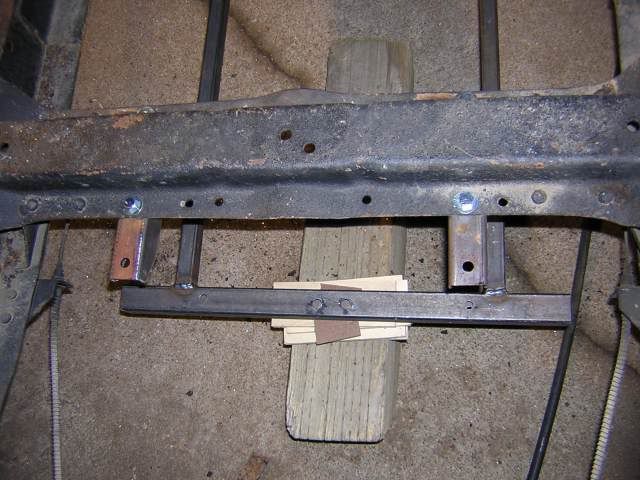
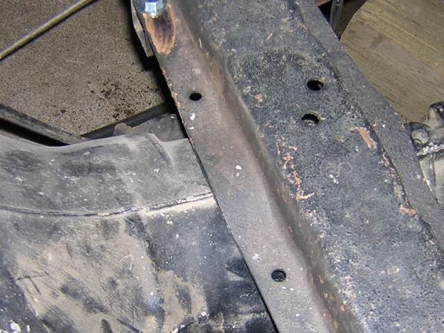
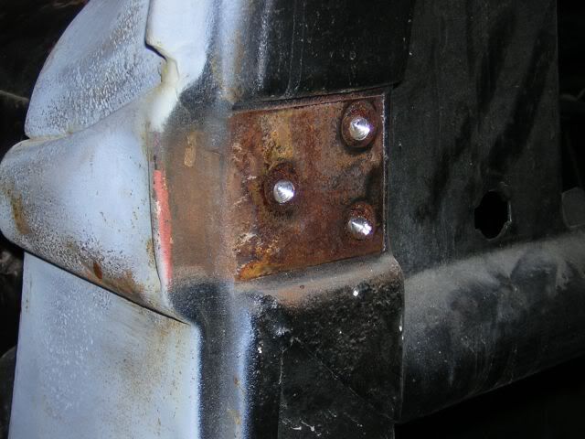
Here is how the rear cab brackets attach to the frame.
Here is how the rear cab brackets attach to the cab.
Here is the driver side bracket.
Dave
Here is how the rear cab brackets attach to the frame.
Here is how the rear cab brackets attach to the cab.
Here is the driver side bracket.
Dave
FTE Stories
Ford Trucks for Ford Truck Enthusiasts

Top 6 Best Deals Available on New Fords & Lincolns Right Now
Brett Foote
This Hennessey Takes the Expedition Tremor's Off-Roading Capability to the Next Level
Verdad Gallardo
Top 10 Fords at 2026 Carlisle Ford Nationals
Joe Kucinski
3 Best / 3 Worst Parts of Modern Ford Ownership
Brett Foote
10 Amazing Upgrades That Solve Common Ford Truck Owner Headaches
Pouria Savadkouei
Every 2026 Ford Engine Explained
Brett Foote
10 Ugly Ford Trucks That We Still Kinda Love
Joe Kucinski
10 Things Every Truck Owner NEEDS (2026 Edition)
Michael S. Palmer
Rezvani's Latest Post-Apocalyptic Monster Is a Ford F-150 Raptor Underneath
Verdad GallardoThread Starter
|
More Turbo
Joined: Jan 2007
Posts: 593
Likes: 15
From: Wichita, KS
I've been using my new bandsaw with a new Morse Bi-metal blade to do all of my cutting. It's not as fast in vertical mode as a torch, but it works. And it's nice and quiet and relatively clean. All the things that chopsaw is not.
Dave
Dave
Thread Starter
|
More Turbo
Joined: Jan 2007
Posts: 593
Likes: 15
From: Wichita, KS
More progress...
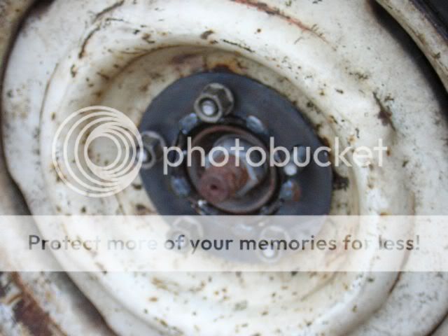
Not much, but I accomplished a little more. The doors are now off of the cab, and I lowered the engine and trans a couple of inches. I also have temporarily gotten around the 4.25" bolt circle of the rear end. Just took a little ingenuity!

The circle cutting jig came in very handy here!
Dave
The circle cutting jig came in very handy here!
Dave
Thread Starter
|
More Turbo
Joined: Jan 2007
Posts: 593
Likes: 15
From: Wichita, KS
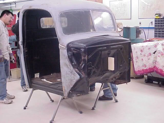
Doors off - here's how!
After much debate about how to get the screws loosened, and a week or so of spraying penetrating oil on the back side of the screws, and one attempt with a socketed #3 Phillips bit, I was still in the air on how I was going to get the doors off. In the end, though, the new used 18V cordless DeWalt drill got the call. It made surprisingly quick work of the screws. I won't need the lower hinge mounting location, and I may modify the upper hinge location anyway, so drilling the screwheads off ended up being the most reasonable way to get the job done.
Dave
Dave
Thread Starter
|
More Turbo
Joined: Jan 2007
Posts: 593
Likes: 15
From: Wichita, KS
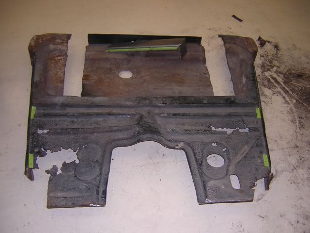
Here are some shots of some replacements made for the floor. I could probably buy the entire floor assembly, but we'll need the practice for when we fab the body panels, so this is good practice.
Old...
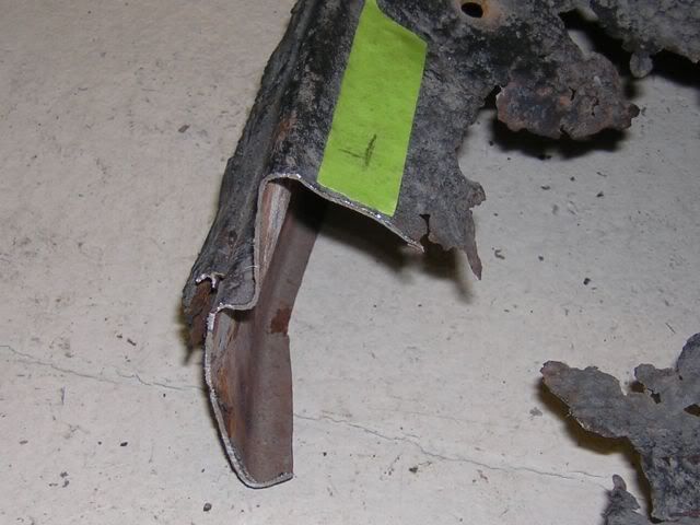
New...
This is the floor as it came out of the truck.
Dave
Old...
New...
This is the floor as it came out of the truck.
Dave
Thread Starter
|
More Turbo
Joined: Jan 2007
Posts: 593
Likes: 15
From: Wichita, KS
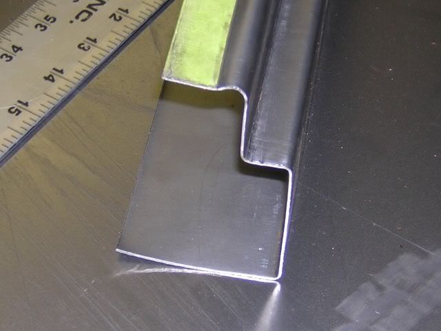
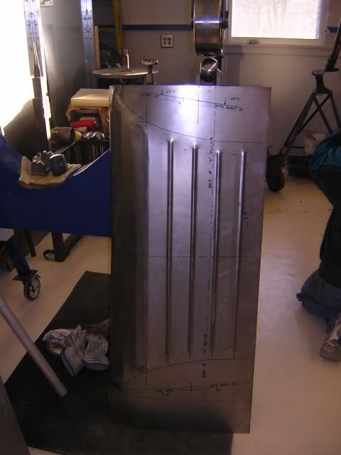
This piece made me say bad words. I found out that beading is not as simple as it seems when the ends of the bead are captured. If they had run the entire width, it'd have been no big deal, but there is quite a bit of pre-stretching required in order to have the panel lay flat after the bead is put in. Or...
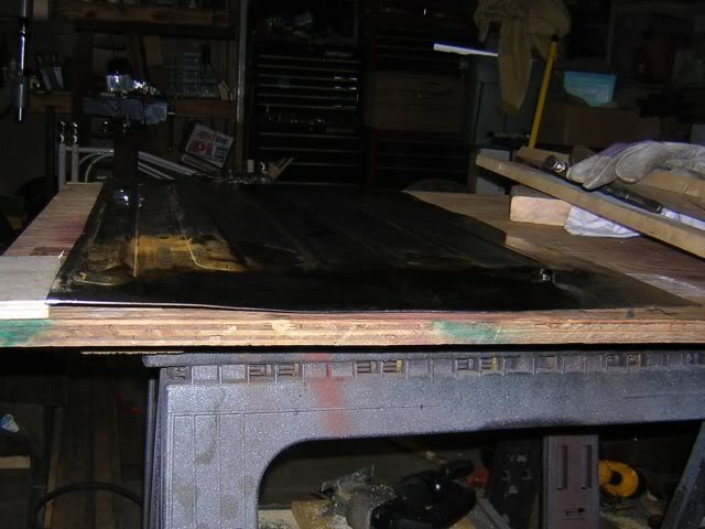
You do what I did. You pre-stretch not-quite-enough and then have to use the shrinking disk and torch to get the ends to lay flat. I think I did pretty good. And I learned about shrinking, so I have a new tool in my arsenal of knowledge.
Here's the panel right after beading. It's hard to tell in this pic, but it had a lot of twist at this point.
Here are the ends after a few hours shrinking them.
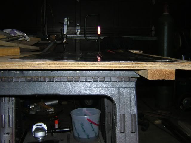
This end doesn't quite lay flat, but that's because of a bow along the long edge that still needs to be taken care of.
Dave
You do what I did. You pre-stretch not-quite-enough and then have to use the shrinking disk and torch to get the ends to lay flat. I think I did pretty good. And I learned about shrinking, so I have a new tool in my arsenal of knowledge.
Here's the panel right after beading. It's hard to tell in this pic, but it had a lot of twist at this point.
Here are the ends after a few hours shrinking them.
This end doesn't quite lay flat, but that's because of a bow along the long edge that still needs to be taken care of.
Dave
