


 All of this advice is heavily based on assumptions of what types of charging system equipment is being used.
351C Regulator Wiring
Hotshot


Joined: Oct 2009
Posts: 16,155
Likes: 4,754
From: Burbank, WA
Fleet Mechanic


Joined: Sep 2010
Posts: 1,831
Likes: 466
From: Mason City, Iowa
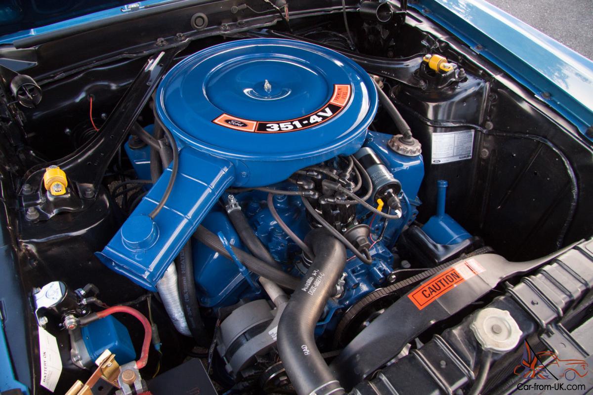
If the alternator and voltage regulator is like the one pictured in that beautiful engine bay above it's a matter of running jumper wires (making a nice wiring harness) between the Voltage Regulator and the Alternator. There will be four connections on the Alternator. The Battery connection uses at least a 10 gauge wire which runs back to the + battery side of your starter relay. On its way there you splice in a wire that connects to the A connection (terminal) on your Voltage Regulator. Some will also fuse the connection between the voltage regulator and the starter relay. (Fuse size depending on your wire size and the max current output of your Alternator. It's not a bad idea.)
Next you run a wire between the "F" or Field connections on your Voltage Regulator and Alternator. Then run another wire between the S or Stator connections between the two units. If you use an electric choke, on a Motorcraft carburetor you could connect it there at your Voltage Regulator "S" terminal. Then a ground wire should be ran between the ground stud on your Alternator and the mounting flange on your Voltage Regulator. Now there is only 1 connection left and that is your "I" terminal on your Voltage Regulator. It needs to run to the switched, 12 volt power side of your Ignition switch. So it has 12 volts when the Ignition Switch is in the ON position. Just like your coil would have, but don't physically connect it to the coil (if an original points style system your coil is connected through a ballast resistor and if you connect right to the coil while the engine is running the voltage is lower at that point. If you do have a ballast resistor you could connect it to the power side of it from the ignition switch, just don't use the coil connection side of that resistor.) If you don't have the 12 volts at the "I" terminal, your Alternator will not charge. Originally that "I" wire ran through a resistor that shorted across an ALT light in the dash. The resistor allowed current to pass through in case the ALT light burned out, still giving you the 12 volt signal to the Voltage Regulator "I" terminal.
I always talk grounds too in these discussions because they get overlooked. Make sure your - battery ground runs right to your engine block. From that point also run a ground cable from the engine block to the frame, and another ground from the engine block to your firewall. With all the rubber in your cab and engine mounts, electric current needs a path back to your battery. Your engine block is a great ground reference point since it needs all that battery current while cranking.
Hope this all helps!
Parts Nerd Extraordinaire
Joined: Sep 2010
Posts: 4,347
Likes: 1,772
From: Western NY

Trending Topics
Fleet Mechanic
Joined: Sep 2010
Posts: 1,831
Likes: 466
From: Mason City, Iowa
Thank You Ross!
I should of just posted a diagram when replying but decided to just write it out. I got too much time on my hands! 😄
I should of just posted a diagram when replying but decided to just write it out. I got too much time on my hands! 😄
FTE Stories
Ford Trucks for Ford Truck Enthusiasts

AEV FXL Super Duty - the Super Duty Raptor Ford Doesn't Make
Brett Foote
Lobo Vs Lobo: Proof the F-150 Lobo Should Be Even Lower!
Michael S. Palmer
Ford's 2001 Explorer Sportsman Concept Looks For a New Home
Verdad Gallardo
10 Best Ford Truck Engines We Miss the Most!
Joe Kucinski
2026 Shelby F-150 Off-Road: Better Than a Raptor R?
Brett Foote
2027 Super Duty Carhartt Package First Look: 12 Things You NEED to Know!
Michael S. Palmer
10 Most Surprising 2026 Ford Truck Features!
Joe Kucinski
Top 10 Ford Trucks Coming to Mecum Indy 2026
Brett Foote
5 Best / 5 Worst Ford Truck Wheels of All Time
Joe Kucinski
Thread
Thread Starter
Forum
Replies
Last Post
vliposky
1967 - 1972 F-100 & Larger F-Series Trucks
2
Nov 19, 2005 03:44 PM