


Instrument Cluster Power Issue

Thread Starter
|
5th Wheeling


Joined: Mar 2021
Posts: 39
Likes: 1
From: Marion, IA
The #977 wire is not a powered wire from the ignition switch. It's a temporary ground wire for testing the bulb each time the key is turned to START.
If you note the point it connects to the switch in the diagram, it's listed as the Prove-Out position. That's the traditional (pre-computer) lamp test. The ignition switch grounds it to the dash when the key is turned to START.
Then the lamp goes back to dormant when the key is released.
Power for the lamp probably comes in from the #932 wire from the switch. That could be a common wire with the instrument cluster, but I can't see it all in the diagram especially with some of the corners cut off and on the smaller screen (that's a "my poor eyes" issue, not yours!) so not sure I'm following all the circuits correctly.
But I think that's correct.
Regarding the cluster regulator, you can't really measure ohms (or at least it takes a specialized method) and you probably would even have trouble measuring voltage using a digital volt meter. With an old analog meter with a needle you can see the needle pulse regularly between about 4v and 8v or so, averaging out to somewhere between 5 and 6 volts if I remember.
It's an electro-mechanical thermally compensating regulator. Only with a modern electronic version will you see a steady voltage output.
So you may have replaced it unnecessarily, but then again it's still hard to say.
Oh, and the diagram we're using here is for the alternator indicator lamp type. Didn't you say earlier you had an ammeter? Sorry if I'm remembering that incorrectly. I'm going to go re-read it, but with so many interruptions in my daily life, I never seem to be able to do anything in just one sitting!
It could mean, as usual, multiple things.
1. It could indicate that the gauges are not receiving the power from the regulator.
2. It could indicate a bad connection between each gauge and it's sending unit.
Those could be bad wires, bad connections, bad grounding method, or bad components still. It's not unheard of (or even unusual anymore) to get several bad ICVR units in a row. The instance of bad parts right out of the box is a rampant issue at the moment. So you can't just replace parts and assume they're helping solve the problem anymore.
Just to help me out, refresh my memory about whether you have the battery charge indicator lamp, or the ammeter.
It might be the case that both types use the same wiring at some points, but it would be standard practice by Ford if connection points in the cluster connector do not match between one type and the other.
Thanks!
Paul
From the diagram, the only ground in the circuit for the gauges looks to be the ground at the fuel tank sending unit. I checked that and no issue there. The only sending unit I didn't ground the wire to see if the gauge pegs was the oil pressure unit. Let's say that wire went bad for some reason. Would that cause all three gauges not to work?
Thread Starter
|
5th Wheeling
Joined: Mar 2021
Posts: 39
Likes: 1
From: Marion, IA
I'll try testing that this weekend again. Tested at the sensor end of the fuel and water temp sending units to ground and look for the gauges to peg and nothing on either. Will try the oil pressure sending unit this weekend also. Not sure if one of those wires to a sending unit is bad, it would keep all three gauges from working?

Lead Driver


Joined: Jul 2017
Posts: 9,616
Likes: 1,183
From: San Jose, CA
How did you check the ground at the sending unit?
And no, a fault in a wire in one gauge sender circuit will not effect any of the others.
The only common thing between the gauges is the power-in from the ignition switch and the illumination power from the headlight switch. But the illumination circuit is not part of the gauge's working functions.
After the power comes in from the common source they become completely independent from each other out to their specific sending units.
Thread Starter
|
5th Wheeling
Joined: Mar 2021
Posts: 39
Likes: 1
From: Marion, IA
They were. But not to the point that you can use the incorrect diagrams to diagnose an issue on your truck. So stop using the wrong "lamps" diagram and get a good "gauges" diagram to use.
The gauges are not grounded per s�. They "ground" through the sending units only. A variable ground if you will...
How did you check the ground at the sending unit?
You need to check them all just to be sure it's still a common issue and does not just happen to be two out of the three with bad wires.
And no, a fault in a wire in one gauge sender circuit will not effect any of the others.
The only common thing between the gauges is the power-in from the ignition switch and the illumination power from the headlight switch. But the illumination circuit is not part of the gauge's working functions.
After the power comes in from the common source they become completely independent from each other out to their specific sending units.
Tested for ground at the water temp sending unit by disconnecting wire at the sending unit, then using another piece of wire to extend that to ground on the radiator support (also tried the negative terminal on battery)
Last edited by Fonckadelic; Dec 8, 2022 at 05:11 PM. Reason: added info

Cargo Master

Joined: Feb 2006
Posts: 3,012
Likes: 251
From: North Pole, Alaska
You are overthinking this again. Just ground the sensor plug on the engine close to the sensor, and check to see if the gauge moves. The same with the oil pressure sensor. Going to the battery is like looking a mile down the street when you just want to cross the road. You might just get a new ICVR from a different place to check.
https://www.uniquecarsandparts.com.a...perature_gauge
https://www.uniquecarsandparts.com.a...perature_gauge
Hotshot


Joined: Mar 2013
Posts: 14,255
Likes: 199
From: Phoenix, Az.
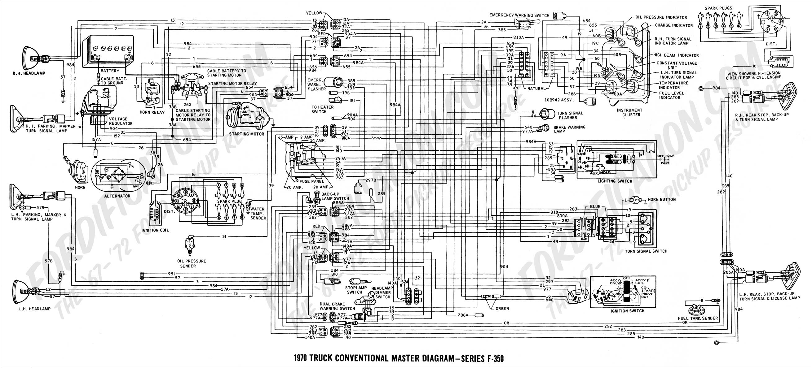
Without re-reading all three pages of this thread, your first post included a schematic of a cluster with idiot lights. You have gauges. I'll include the schematic for a F350 to get the gauges. It looks like circuit #30 powers the CVR. Which powers all gauges except the ammeter. With key on, check for power at the CVR referenced by #30. If you can't tell which is 30, check both wires to the CVR. If no power to the CVR, then there is a bad wire CVR to fuse box. Or the back side of the fuse box has a problem. Corrosion,rust,etc.
Lead Driver
Joined: Jul 2017
Posts: 9,616
Likes: 1,183
From: San Jose, CA
Always a good idea to check/clean the fuse panel stuff. But wire #30 is powered directly from the ignition switch, and so does not have a fuse or any source from the fuse panel.
The connection to the fuse panel via #297a and accessory plug via #297b are from that splice where #30 joins up. So the connection to the fuse panel is showing how the fuse panel gets it's switch power.
Same as #30, direct from the ignition switch.
Not sure what wire color will be at the cluster voltage regulator/ constant voltage regulator, but it was Black w/green on the other diagram.
And in a pinch, the standard practice for the regulators is to use an insulated/female terminal on the wire coming in with power, and an uninsulated/male terminal on the wire heading out to the instruments.
Look for that type of connector and see what you get.
Paul

Cargo Master

Joined: Dec 2015
Posts: 2,255
Likes: 346
[QUOTE=Fonckadelic;20657811] After I replaced the bulb for the brake warning light in the lower left dash, it stays on when key is in start position and after truck started.
The light bulb for the brake pressure differential valve could have been burnt out from a brake issue. When my 70 f250 brake light was on, I had to remove it and take it apart to get the internal rod re-centered. Then I replaced the brakes on the front and bled the brakes. It moved again while bleeding the brakes but with some driving and braking, it re-centered.
The light bulb for the brake pressure differential valve could have been burnt out from a brake issue. When my 70 f250 brake light was on, I had to remove it and take it apart to get the internal rod re-centered. Then I replaced the brakes on the front and bled the brakes. It moved again while bleeding the brakes but with some driving and braking, it re-centered.
FTE Stories
Ford Trucks for Ford Truck Enthusiasts

Top 6 Best Deals Available on New Fords & Lincolns Right Now
Brett Foote
This Hennessey Takes the Expedition Tremor's Off-Roading Capability to the Next Level
Verdad Gallardo
Top 10 Fords at 2026 Carlisle Ford Nationals
Joe Kucinski
3 Best / 3 Worst Parts of Modern Ford Ownership
Brett Foote
10 Amazing Upgrades That Solve Common Ford Truck Owner Headaches
Pouria Savadkouei
Every 2026 Ford Engine Explained
Brett Foote
10 Ugly Ford Trucks That We Still Kinda Love
Joe Kucinski
10 Things Every Truck Owner NEEDS (2026 Edition)
Michael S. Palmer
Rezvani's Latest Post-Apocalyptic Monster Is a Ford F-150 Raptor Underneath
Verdad Gallardo
Thread
Thread Starter
Forum
Replies
Last Post
Combatvet78
1973 - 1979 F-100 & Larger F-Series Trucks
1
Jun 14, 2021 08:23 AM
Christopher Workman
1980 - 1986 Bullnose F100, F150 & Larger F-Series Trucks
16
Mar 3, 2018 08:59 AM
ticorover
1973 - 1979 F-100 & Larger F-Series Trucks
1
Mar 9, 2011 04:35 PM