When you click on links to various merchants on this site and make a purchase, this can result in this site earning a commission. Affiliate programs and affiliations include, but are not limited to, the eBay Partner Network.
1995 Ford F-150 XLT ext, 5.0 MAF, RWD, Auto 4R70W, Lapis Metallic, 150k
Hey fellas, awesome forum here, its helped me a lot in the past, and trust it to help me further.
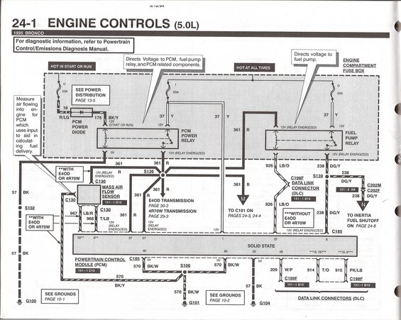
So, I've got an issue with getting the right voltage to one of the wires leading into the MAF sensor. Key On, I see 12 volts in wires "A" and "B" as described on the sensor, power and ground respectively, but wire "C"("ECM Ground") is getting about 6 volts. I have not proceeded to the running test. I checked the resistance from the maf connector to the ecm connector(pin 9), and it seems fine.
What else could be causing the short? Any fuses or relays possibly affecting this circuit? Rather new to electrics and diagnostics in general so any help would be much appreciated.
I have just recently changed the pins in the connector because I had probed one of the wires an inch or so back of the terminal and found 12 volts, while seeing 6 volts inside the rear of the terminal using a t-pin, and had assumed that's where the short was. I also recall seeing 12 volts from pin 9 of the ecm. Now I'm seeing 6 everywhere. New wires are 14 awg instead of stock 18. Getting code 158 when warm, key on. "High voltage to MAF."
I'm using a t-pin to probe the back of the connector, touching the rear of the terminal.
back probing is not the proper way to probe that, but YOU CUT OFF THE ORIGINAL CONNECTOR?
You could just depin the thing and then put them in a new body
You should only use gold plated terminals on the critical as hell connectors like the MAF, TPS etc.
at least ford said that not me
And the wire you back probed, what is the reading when not connected to the sensor?
I've yet to get some proper probing accessories for my multimeter, true. The t-pins have worked fine as far as I can tell. No damage caused... that I know of anyhow.
I wasn't sure if the original "short" in the last inch of the wiring leading into the connector was caused by a wire probe damaging the copper, or the pin at the end, so it made sense just to cut off before the area where I saw 12v and solder it back on with the new wires and pins. Wire A and B getting 12v same as they were.
Don't know anything about any gold. These are what I got from the dealership, and after failing to find any markings or information on the pins online, I was just glad to get something that looked remotely similar.
All 3 were tested KO, unplugged from the sensor. 12 volts power, 12 volts ground, 6 volts ECM Ground(ABC, going right to left).
I am having a trouble finding definitive info but if that wire you speak of is 6 volts, then you should see if other 5 volt referenced things are also 6 volts, I dont know if any share that reference or etc. 5v references sometimes are separate for MAF and EGR ive noticed
There is a MAF sensor test online that uses a meter referenced to the POSITIVE battery terminal to verify the ground and Signal Return. With a meter lead on the positive (+) terminal and the other on Pin C of the MAF sensor you should see +12 VDC assuming the red meter lead is on the positive terminal and Signal Return is good. Since the OP is seeing 6 VDC that is usually an indication there is an open in the Signal Return circuit. Had this same issue on a relatively recent thread. Turned out the OP of that post had a bad computer. Signal Return for the MAF was bad internally to the computer. IMHO that is not a common failure scenario.
For this thread I HIGHLY suggest to verify the circuit from the MAF sensor to the computer is good.
It's a bit confusing until you read the instructions to use the positive terminal of the battery as a reference to test the ground and Signal Return. Personally I would use the NEGATIVE battery terminal as the reference and set the meter/DVM to ohms to test ground and Signal Return.
Does the MAF use the PCM ground on the core support or is that ground dedicated for something like the ECT.
Ford terminology kinda messes with my wrap on electrical stuff since I learned off GM stuff, and ford had a knack for wording things different to be.. well.. different lol.
looking at EEC sensor naming LOL (before ISO standardization)
I'm using a t-pin to probe the back of the connector, touching the rear of the terminal.
I meant what was each probe connected to to get 6 volts . Red probe hooked to battery positive terminal and black prob to pin c? You don't measure A B C all the same way without reconfiguring your probes
A should have 12 volts available. B and C should have 0 volts on them as they are grounds.
The MAF Signal Return eventually makes it way back to G101 which is near the battery.
Ohh
Is that the fender ground with multiple lugged items? Or is this on the core support, frame, or some place creative?
Do you know what proper MAF voltage should be for a 96? I dont trust a ford TSB on the subject despite it clearly being for the application, but the values I get for the MAF seem to be rational and jive with others. but I didnt know if maybe the fact it doesnt go much over 3,4 volts(IIRC) Is due to the fact the same MAF goes on engines which suck and toot much more air than a i6
Ohh
Is that the fender ground with multiple lugged items? Or is this on the core support, frame, or some place creative?
The ground lead next to the battery is G101:
The power ground for the MAF is tied to G101 with a splice where PCM Pins 40 and 60 are also tied to G101. Signal Return for the MAF goes to PCM Pin 9 where I believe it gets tied to other Signal Returns internally that make their way back to G101.
Originally Posted by AuroraGirl
Do you know what proper MAF voltage should be for a 96?
I do not. Never had the need to troubleshoot one to be honest.
The power ground for the MAF is tied to G101 with a splice where PCM Pins 40 and 60 are also tied to G101. Signal Return for the MAF goes to PCM Pin 9 where I believe it gets tied to other Signal Returns internally that make their way back to G101.
I do not. Never had the need to troubleshoot one to be honest.
I actually miss spoke, I meant to say MAF. The MAF should be same voltage range on all maf I6, but if the answer is the same thats ok
There is a MAF sensor test online that uses a meter referenced to the POSITIVE battery terminal to verify the ground and Signal Return. With a meter lead on the positive (+) terminal and the other on Pin C of the MAF sensor you should see +12 VDC assuming the red meter lead is on the positive terminal and Signal Return is good. Since the OP is seeing 6 VDC that is usually an indication there is an open in the Signal Return circuit. Had this same issue on a relatively recent thread. Turned out the OP of that post had a bad computer. Signal Return for the MAF was bad internally to the computer. IMHO that is not a common failure scenario.
For this thread I HIGHLY suggest to verify the circuit from the MAF sensor to the computer is good.
It's a bit confusing until you read the instructions to use the positive terminal of the battery as a reference to test the ground and Signal Return. Personally I would use the NEGATIVE battery terminal as the reference and set the meter/DVM to ohms to test ground and Signal Return.
Sure enough, that�s the same testing procedure I used in the beginning to find the low voltage, even before getting a CEL after already swapping the MAF sensor, repinning the connector, and swapping in a reman ECM.
Just got inside after testing the resistance between GND(Wire B) and NEG, SIG RTN(Wire C) and Pin 9, and MAF SIG(Wire D) and Pin 50. All check out. SIG RTN and NEG did not register. Neither did MAF SIG and SIG RTN, nor MAF SIG and NEG as in the test in AuroraGirl�s post, unless it meant another configuration.
So, circuit from MAF connector to ECM connector is fine. SIG RTN to NEG does not register a circuit. If the SIG RTN circuit is split at the ECM, maybe another sensor�s SIG RTN has a short that�s stealing voltage when power is on?
I meant what was each probe connected to to get 6 volts . Red probe hooked to battery positive terminal and black prob to pin c? You don't measure A B C all the same way without reconfiguring your probes
A should have 12 volts available. B and C should have 0 volts on them as they are grounds.
Yeah, done as you and the link shared above had stated, red probe to positive to measure grounds in MAF connector with KO.
This Hennessey Takes the Expedition Tremor's Off-Roading Capability to the Next Level
Slideshow: The VelociRaptor Expedition gains a lift, upgraded suspension, Brembo brakes, and trail-ready equipment while retaining the stock 440-horsepower EcoBoost V6.
Rezvani's Latest Post-Apocalyptic Monster Is a Ford F-150 Raptor Underneath
Slideshow: Called the Fortress, the 850-horsepower pickup combines Raptor underpinnings with military-inspired features, survival equipment, and a starting price of $285,000.