


Butt welds for patch panels.
Thread Starter
|
Tuned


Joined: Aug 2007
Posts: 457
Likes: 115
From: Maryland
Butt welds for patch panels.
Some basic stuff in replacing previous patches with better patches, trimming and tacking. Hopefully this will help out someone with patch panels.
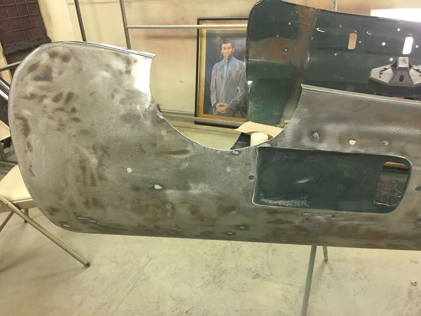
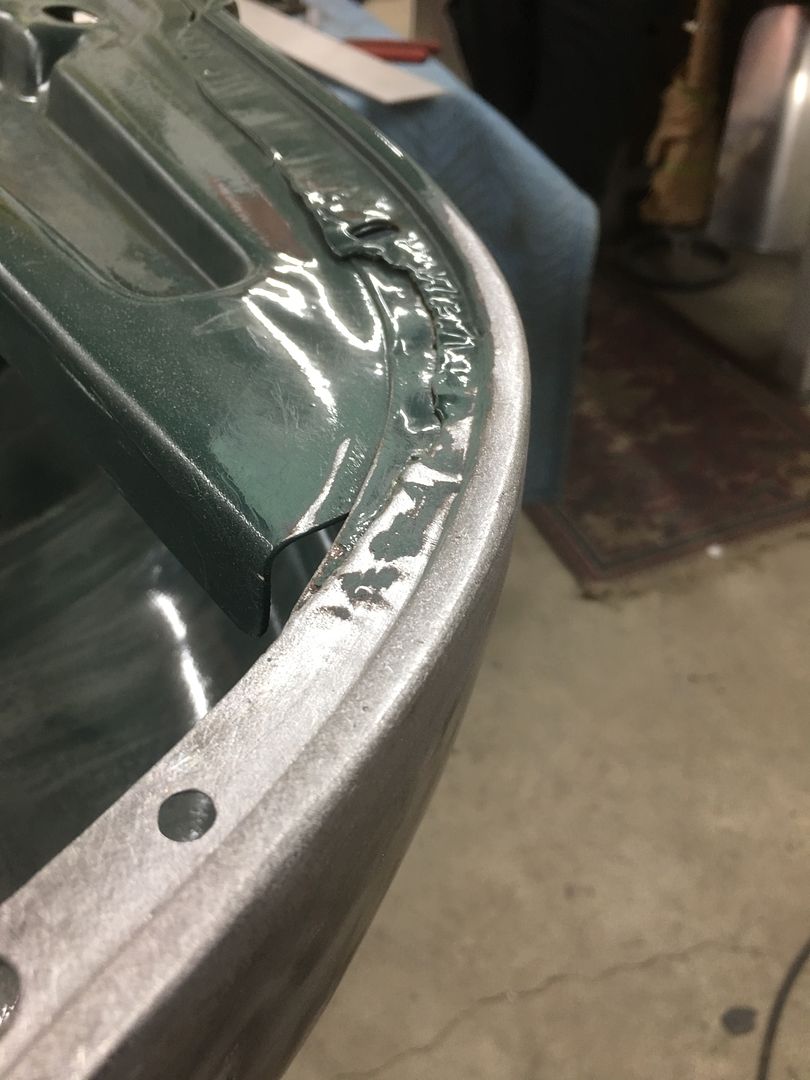
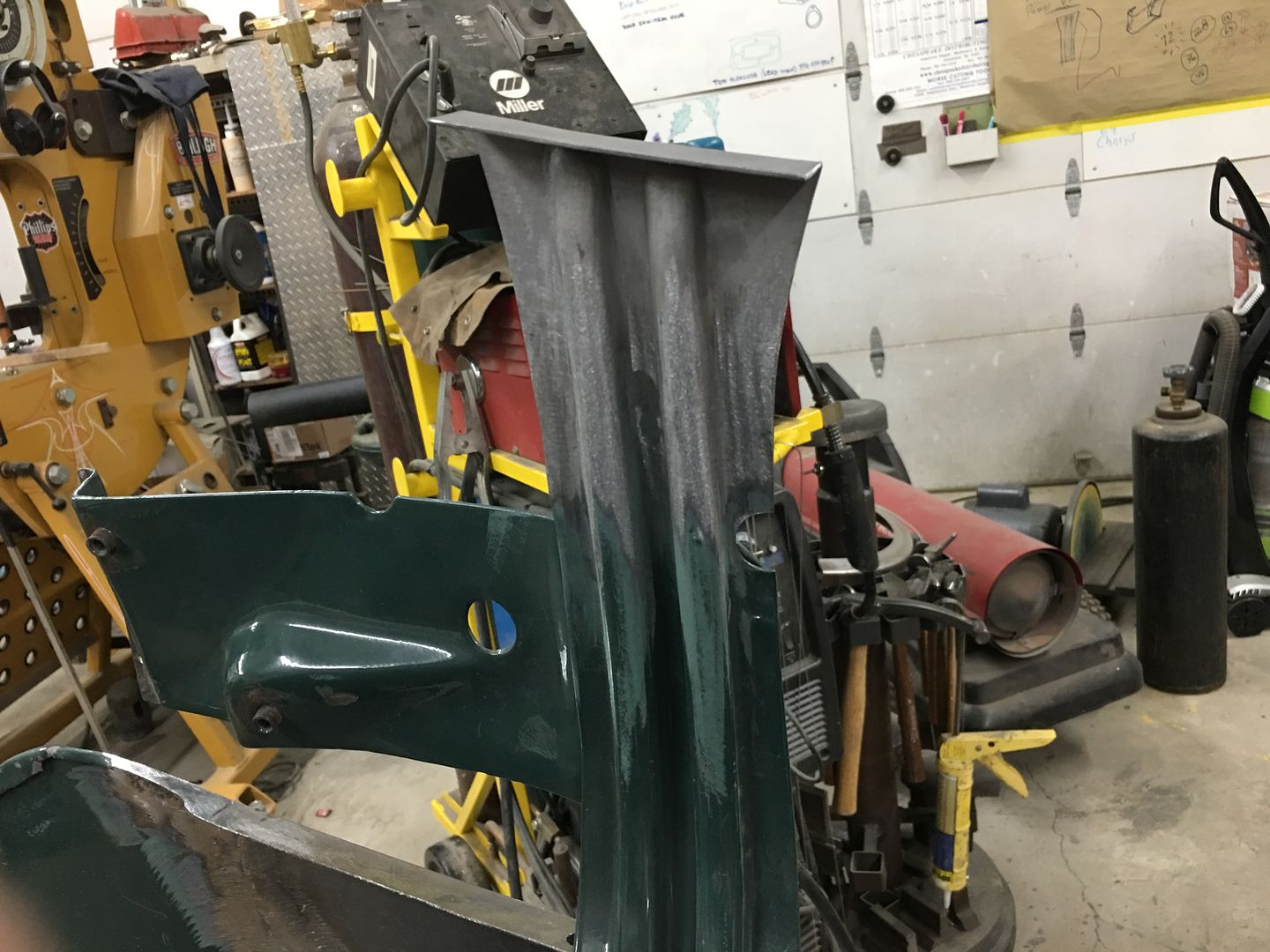
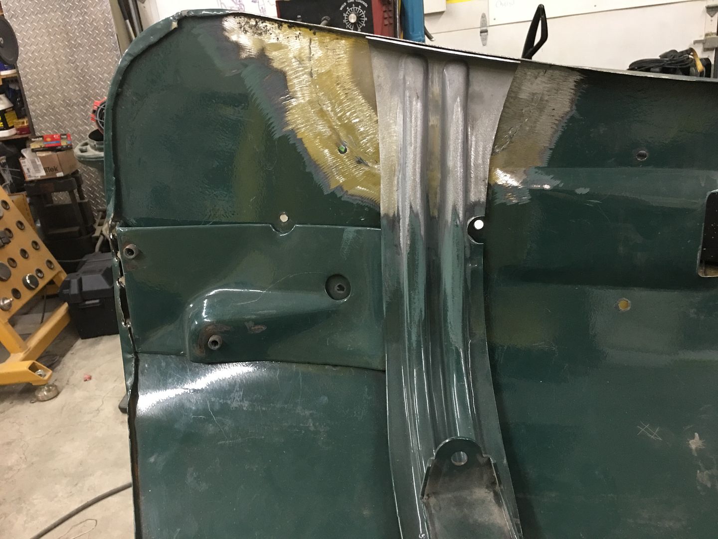
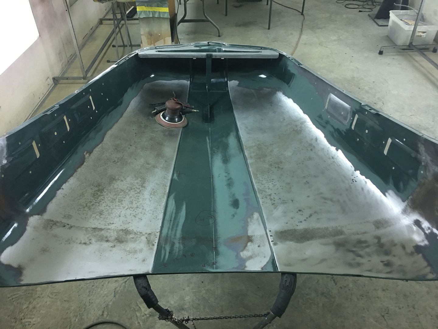
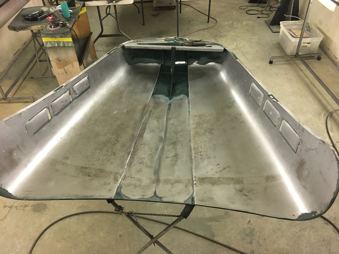
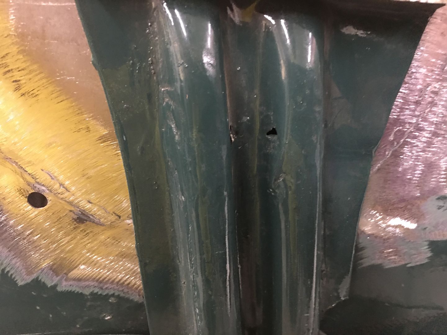
Our shop has a new project from the local owner of a 51 Ford F7 with a Rollback body. He was driving it down the road a few months back when the Delco Remy voltage regulator on the firewall malfunctioned and resulted in an electrical fire. The heat caused some of the filler on the outside of the hood above the fire to delaminate, showing up as circles in the paint. As we sanded these defects out it was noticed that an abundance of filler (+1/4") had been used. The more we looked, the more filler we found all over the hood. In an effort to yield some weight savings, the entire outside of the hood was stripped..
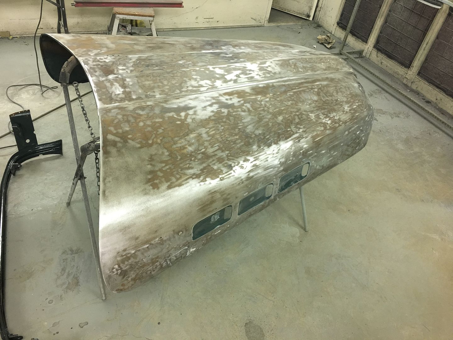
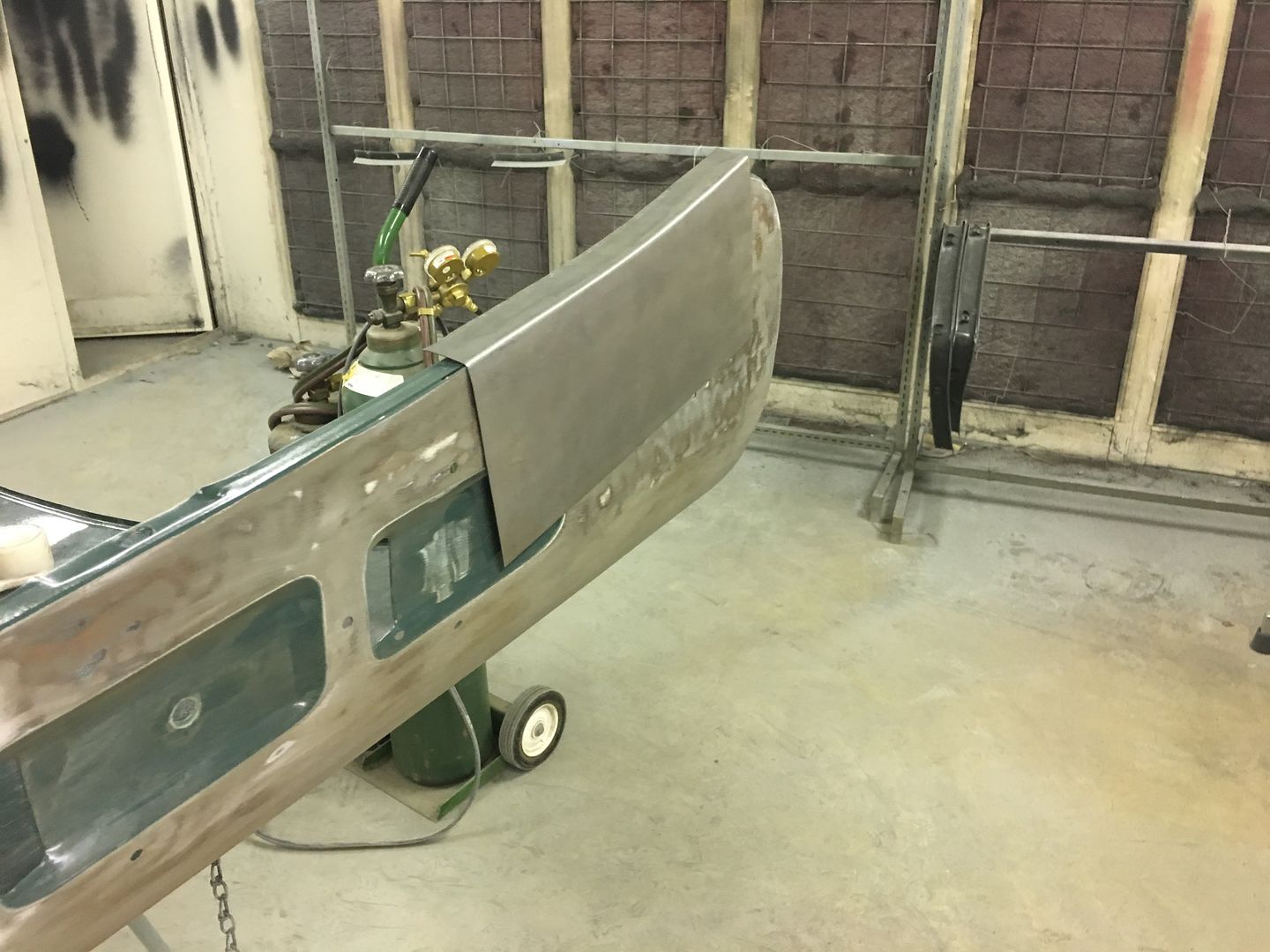
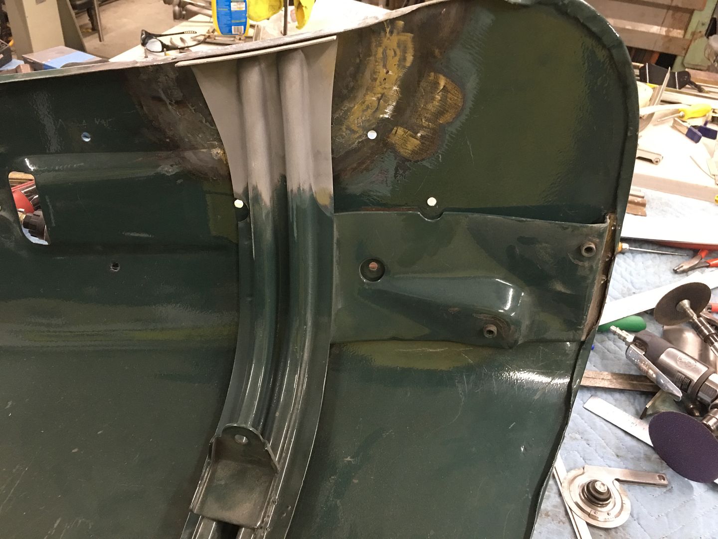
In order to have free access for planishing out the Atlantic Ocean defects, the hood brace was removed from the inside...
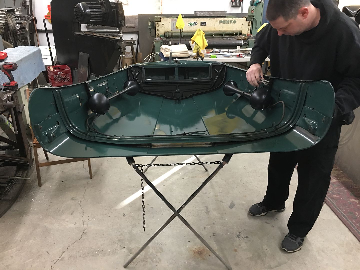
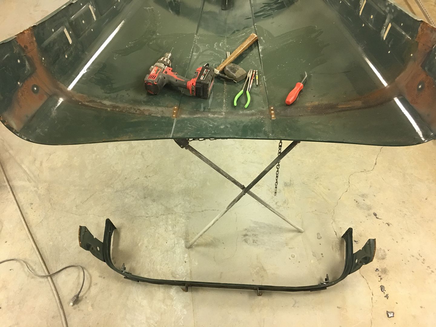
This revealed more defects that the last shop saw as fixes, but they won't leave my shop like that....
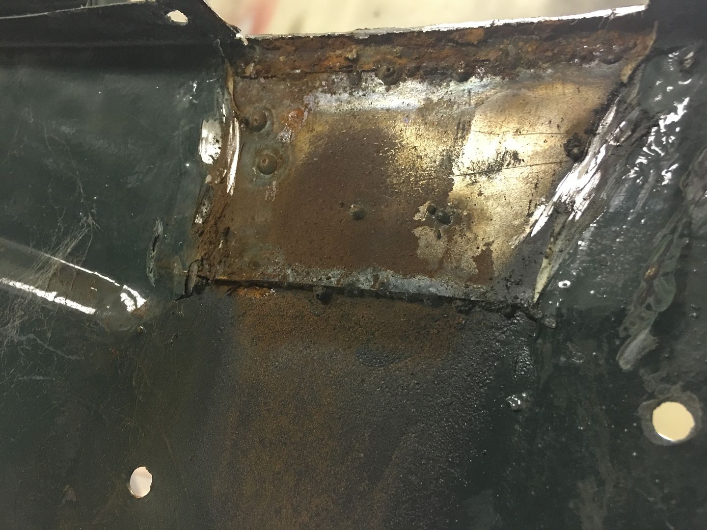
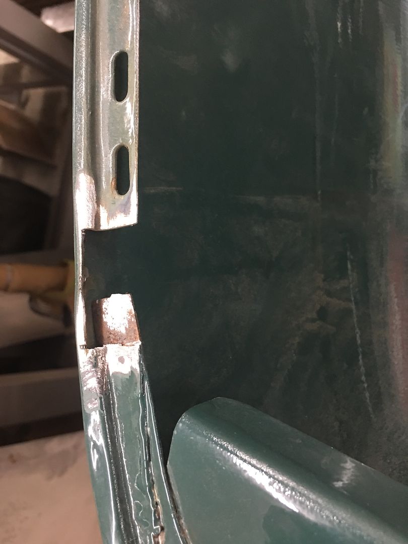
Rather than butt weld in the proper thickness metal, a piece of about 16 gauge is slipped behind the rust hole area (from dirt accumulating between brace and hood skin) and MIG welded around the perimeter. I think we can improve on that..
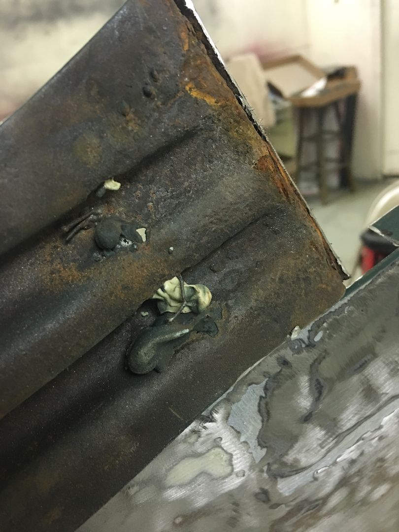
In addition to that, the brace had lost it's structural integrity, so we will remake the ends..
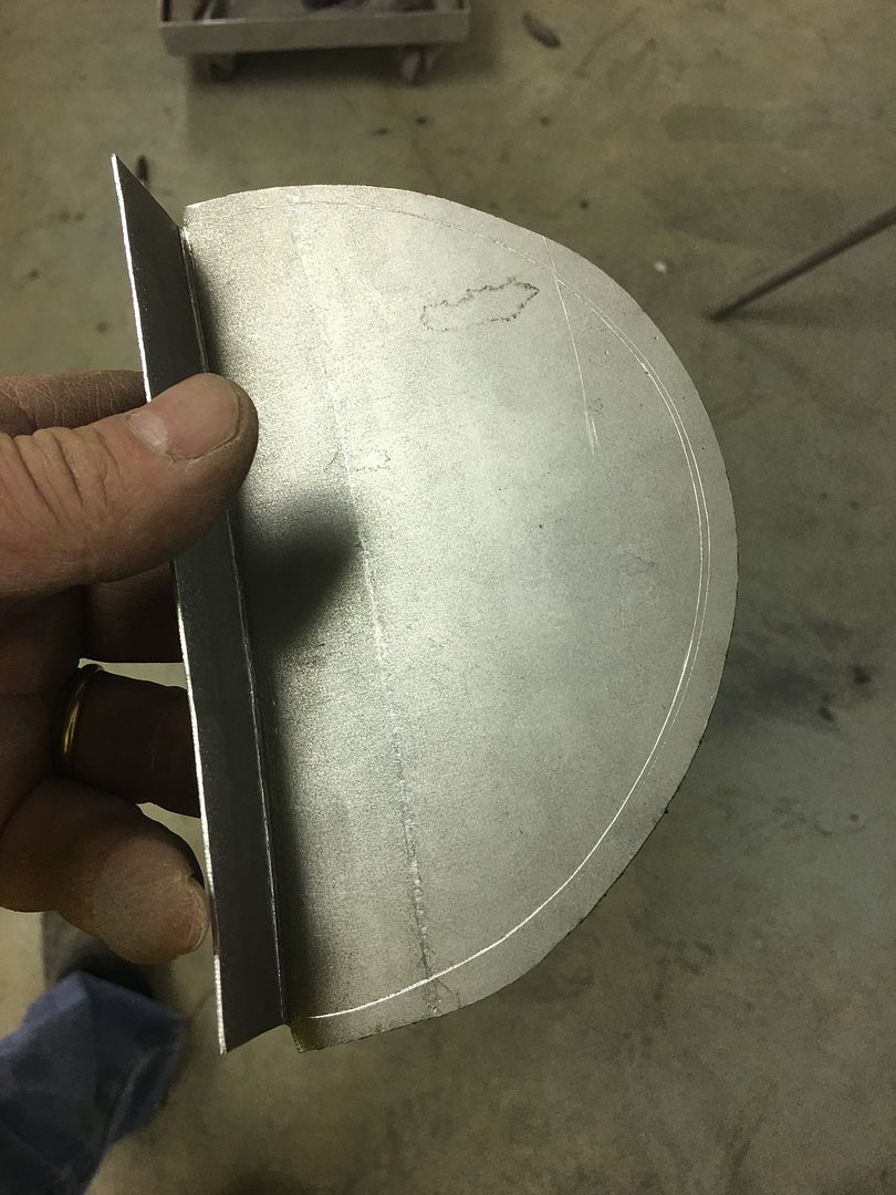
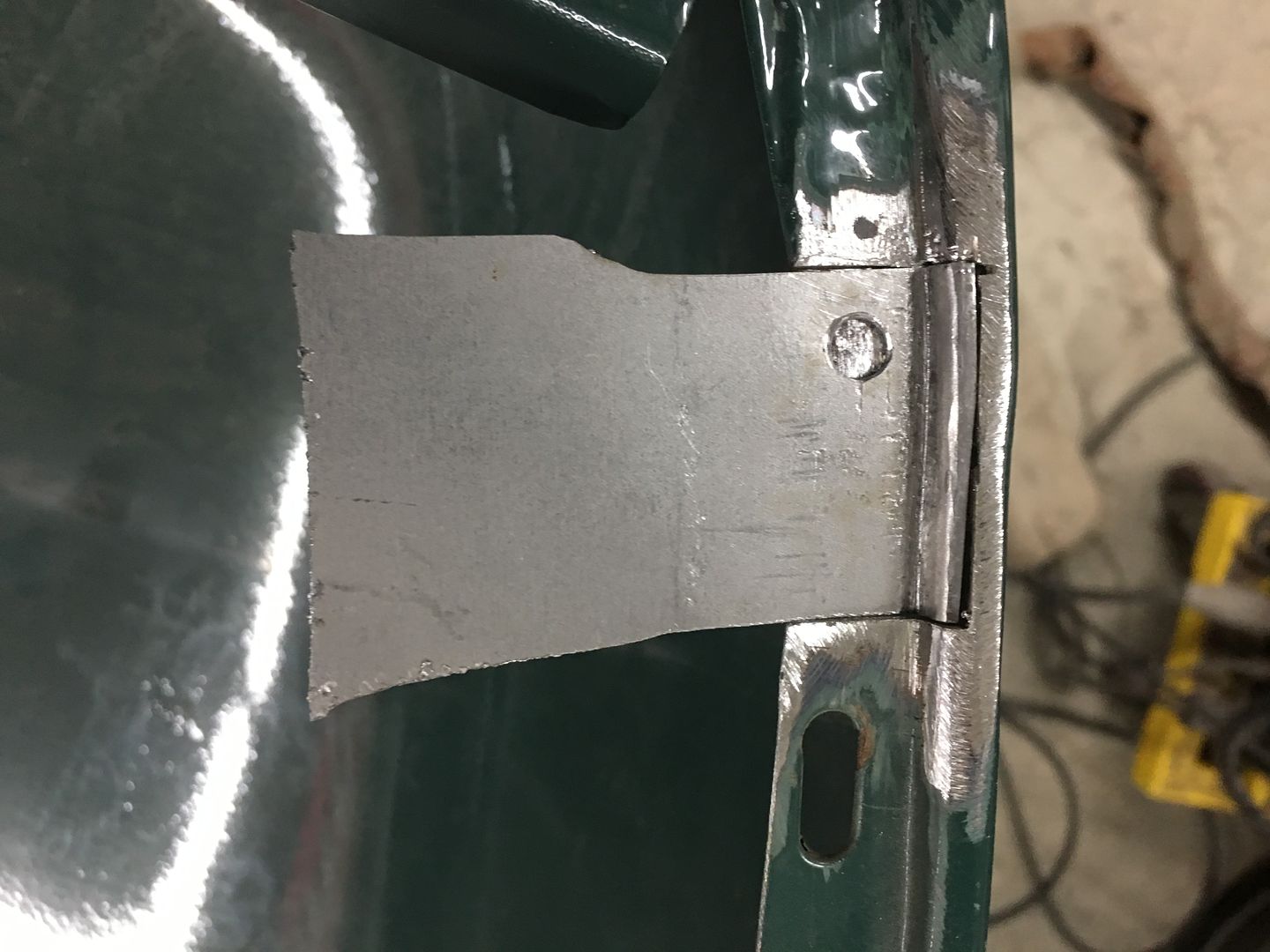
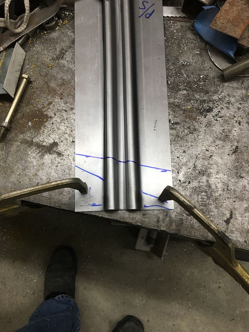
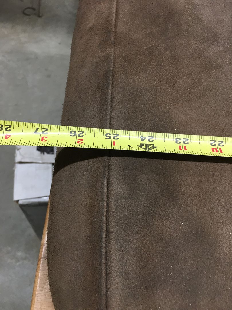
To start our repairs, a body sweep is used to capture the lower flange profile. Note that a profile cut out of construction paper/cardboard works as well.
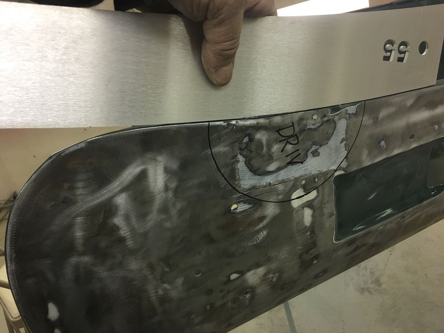
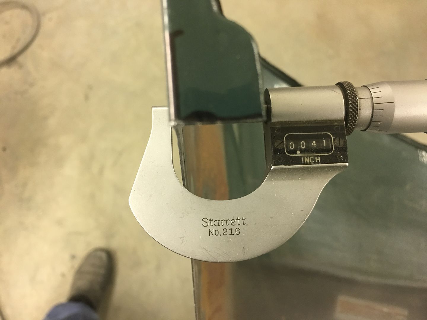
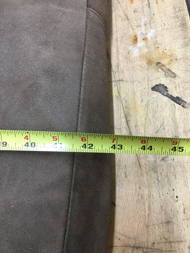
Verifying the panel thickness. Despite this being an early 50's truck, despite this being a BIG truck, yes, the outer sheet metal here is STILL only 19 gauge.
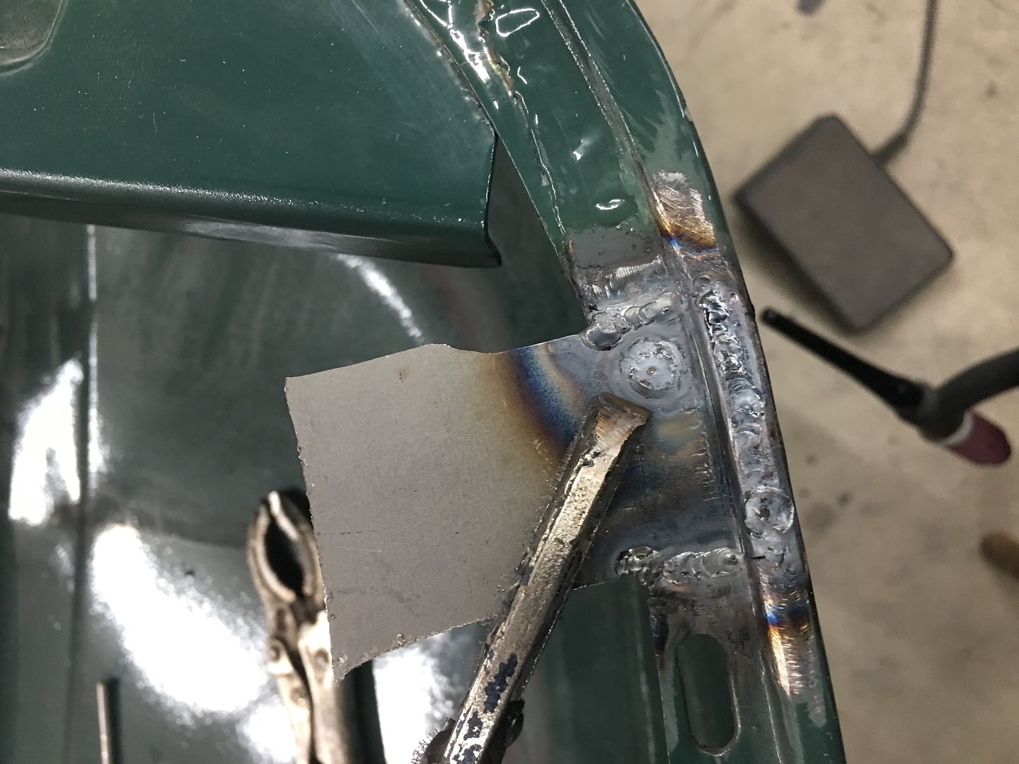
The affected area was cut out using an air body saw, use what you have available. Note we have no corners in the cut to help improve consistency in weld shrinkage on either side.
The flange bend line is traced from our profile template/body sweep, and bent using tipping wheel on the bead roller (since it's not a straight bend). Here test fitted to the hood..
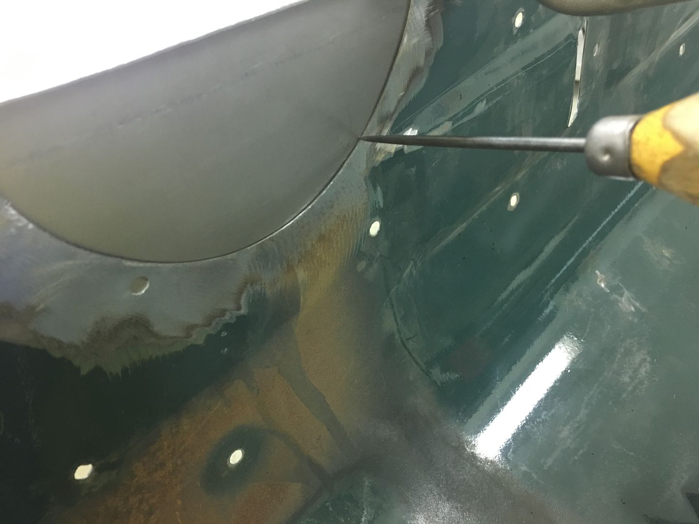
An Ice Pick (something everyone should have if doing this type of work) is used to mark the area of the cut and more importantly, the cuts for the flanges.
Next we trim the panel on the band saw leaving 1/4" extra around our marks. Next, we use offset snips and trim the flanges to the lines scribed. And ONLY the flanges.. Then the panel is re-fitted with the flanges flush with the original, and RE-scribe the round line, this time with more force to see the mark better.
Note the scribe line has moved closer toward the flange as we located the panel correctly with flanges flush..
Fitted... panel should be as tight as you can get it to minimize any shrinking/pulling.
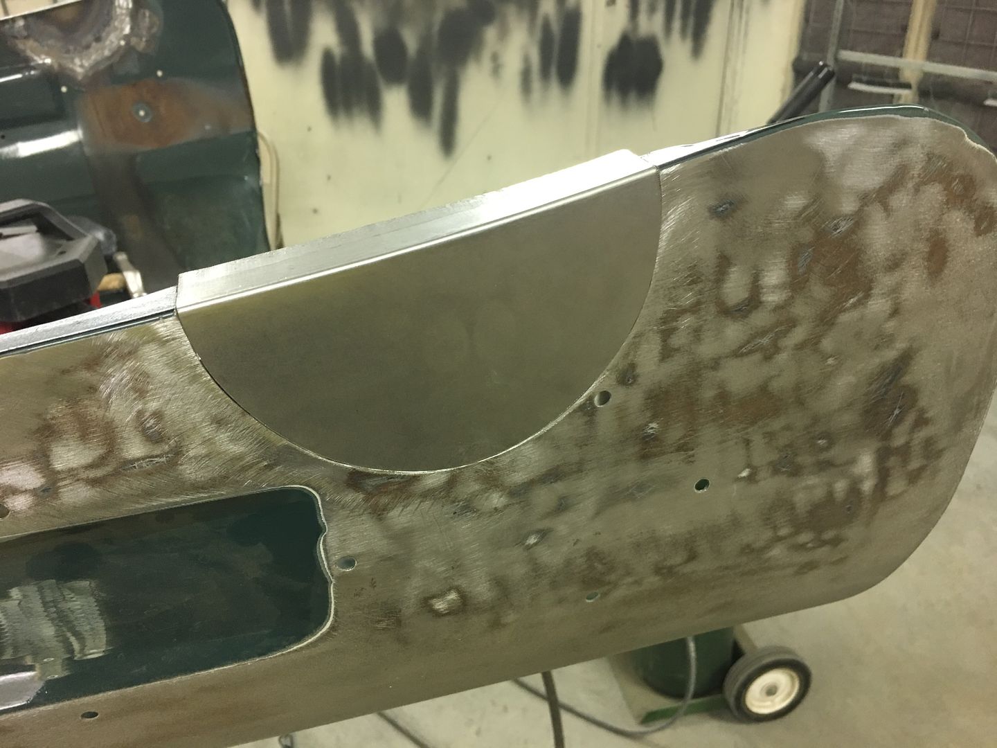
Flanges and outer surface are both aligned to the original first and I use TIG to tack on the exact corner on both ends to maintain this alignment.. Side note.... tacking only one end and working around to the other may shrink as you go, pulling other end down where it no longer aligns. So in this case, align both ends, tack both ends, and then progressively work your tacks side to side toward the bottom of the circle.
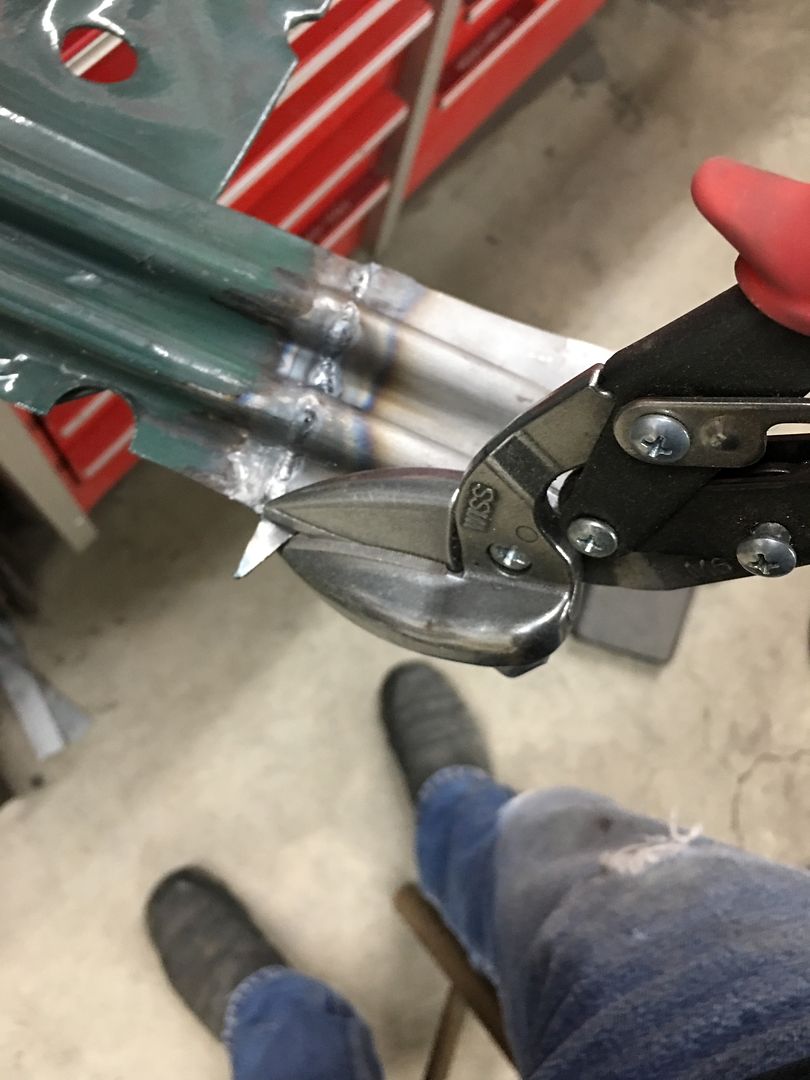
Note here the flange was left long on our replacement. Trying to weld it in place already trimmed to fit will invariably cause the edge to burn back, making it more difficult to weld this seam all the way to the edge. Leaving the flange on our patch long makes the outer part serve as a heat sink where this burn back effect is less of an issue. Once the welds are dressed, trim the excess using offset snips..
Our shop has a new project from the local owner of a 51 Ford F7 with a Rollback body. He was driving it down the road a few months back when the Delco Remy voltage regulator on the firewall malfunctioned and resulted in an electrical fire. The heat caused some of the filler on the outside of the hood above the fire to delaminate, showing up as circles in the paint. As we sanded these defects out it was noticed that an abundance of filler (+1/4") had been used. The more we looked, the more filler we found all over the hood. In an effort to yield some weight savings, the entire outside of the hood was stripped..
In order to have free access for planishing out the Atlantic Ocean defects, the hood brace was removed from the inside...
This revealed more defects that the last shop saw as fixes, but they won't leave my shop like that....
Rather than butt weld in the proper thickness metal, a piece of about 16 gauge is slipped behind the rust hole area (from dirt accumulating between brace and hood skin) and MIG welded around the perimeter. I think we can improve on that..
In addition to that, the brace had lost it's structural integrity, so we will remake the ends..
To start our repairs, a body sweep is used to capture the lower flange profile. Note that a profile cut out of construction paper/cardboard works as well.
Verifying the panel thickness. Despite this being an early 50's truck, despite this being a BIG truck, yes, the outer sheet metal here is STILL only 19 gauge.
The affected area was cut out using an air body saw, use what you have available. Note we have no corners in the cut to help improve consistency in weld shrinkage on either side.
The flange bend line is traced from our profile template/body sweep, and bent using tipping wheel on the bead roller (since it's not a straight bend). Here test fitted to the hood..
An Ice Pick (something everyone should have if doing this type of work) is used to mark the area of the cut and more importantly, the cuts for the flanges.
Next we trim the panel on the band saw leaving 1/4" extra around our marks. Next, we use offset snips and trim the flanges to the lines scribed. And ONLY the flanges.. Then the panel is re-fitted with the flanges flush with the original, and RE-scribe the round line, this time with more force to see the mark better.
Note the scribe line has moved closer toward the flange as we located the panel correctly with flanges flush..
Fitted... panel should be as tight as you can get it to minimize any shrinking/pulling.
Flanges and outer surface are both aligned to the original first and I use TIG to tack on the exact corner on both ends to maintain this alignment.. Side note.... tacking only one end and working around to the other may shrink as you go, pulling other end down where it no longer aligns. So in this case, align both ends, tack both ends, and then progressively work your tacks side to side toward the bottom of the circle.
Note here the flange was left long on our replacement. Trying to weld it in place already trimmed to fit will invariably cause the edge to burn back, making it more difficult to weld this seam all the way to the edge. Leaving the flange on our patch long makes the outer part serve as a heat sink where this burn back effect is less of an issue. Once the welds are dressed, trim the excess using offset snips..
Thread Starter
|
Tuned
Joined: Aug 2007
Posts: 457
Likes: 115
From: Maryland
More patches to go!
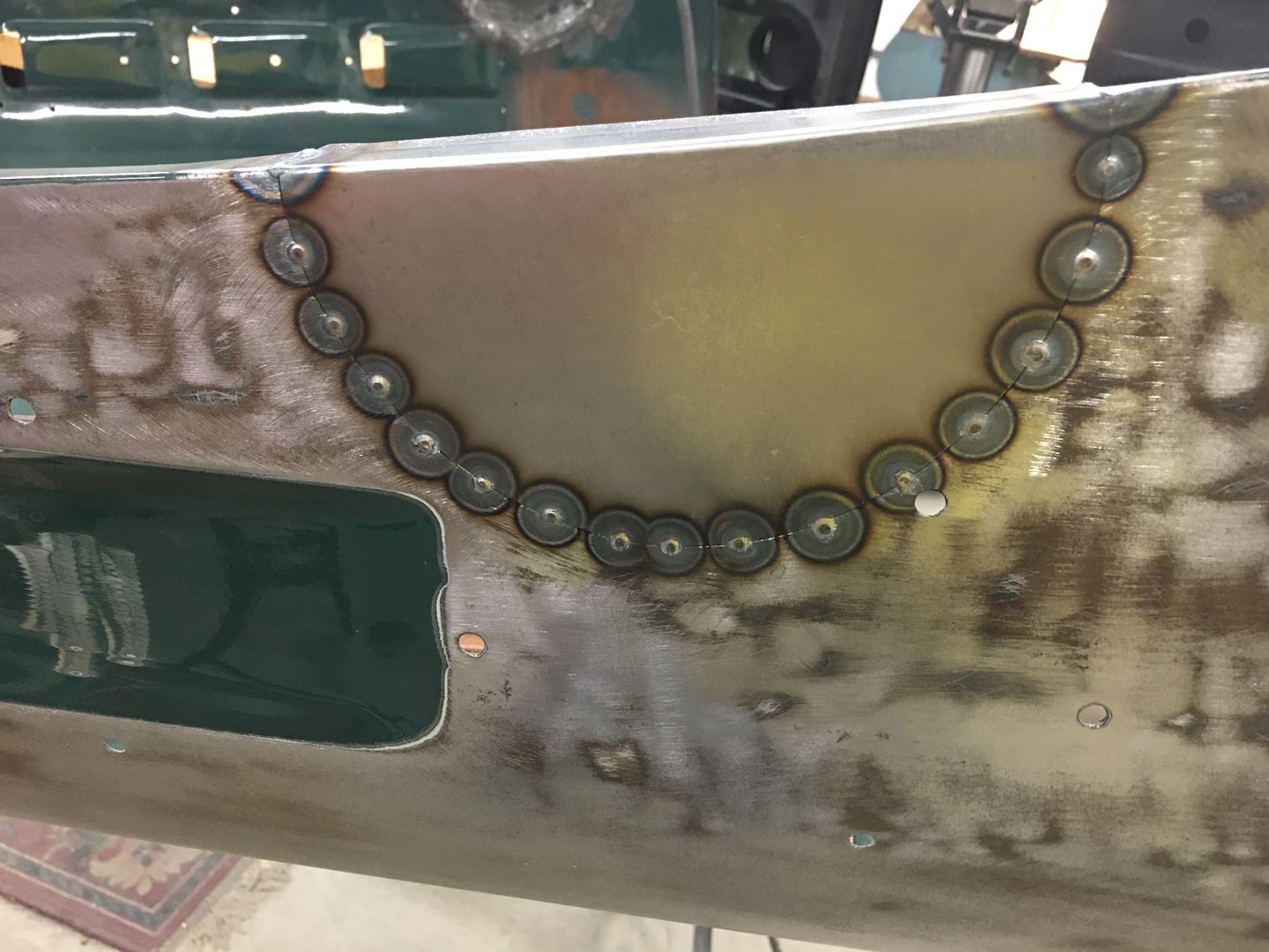
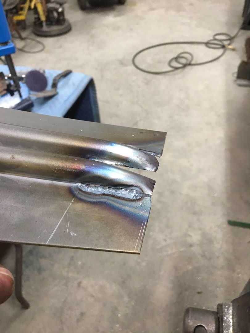
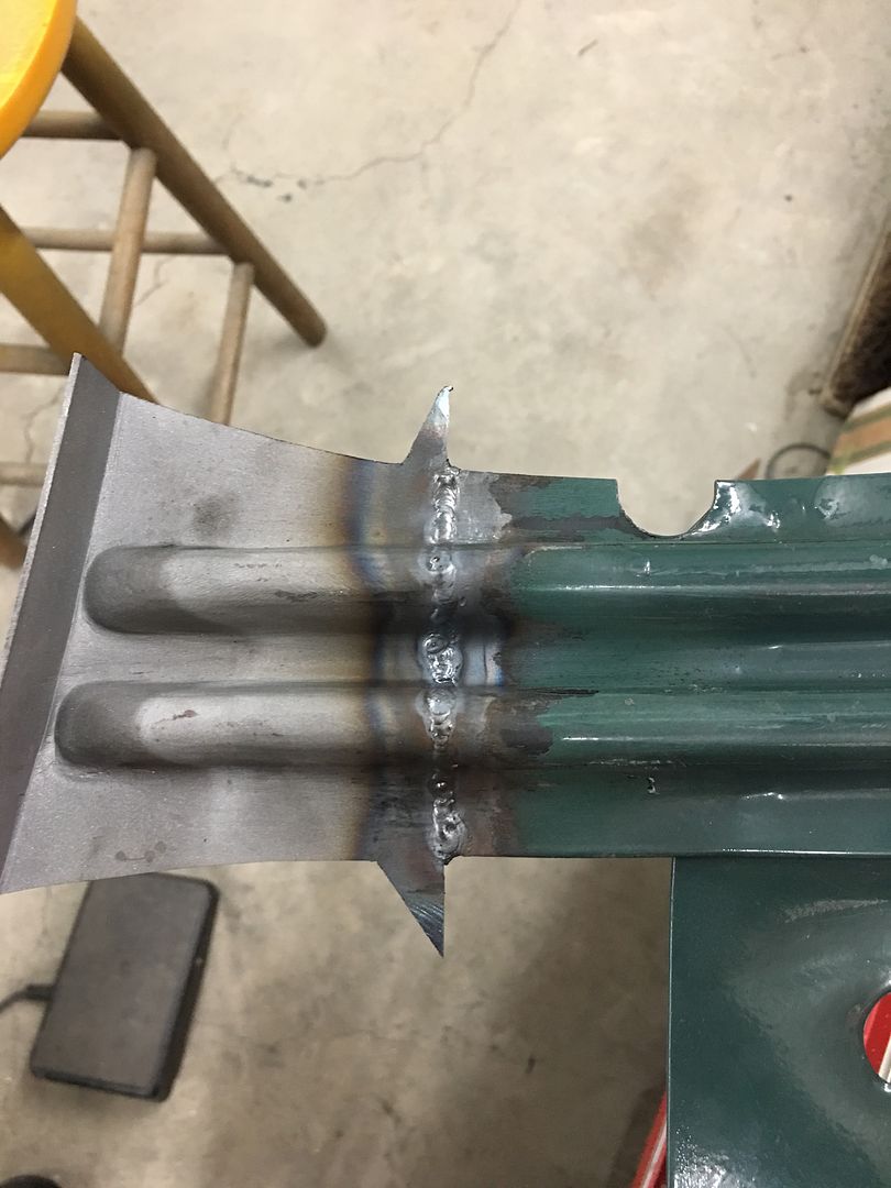
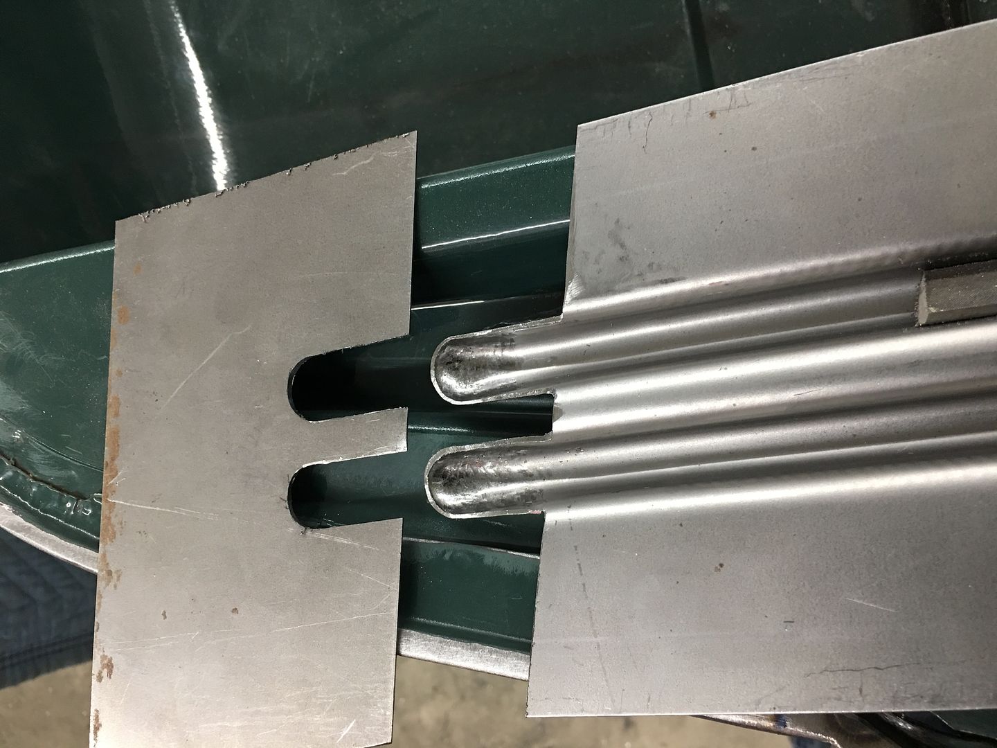
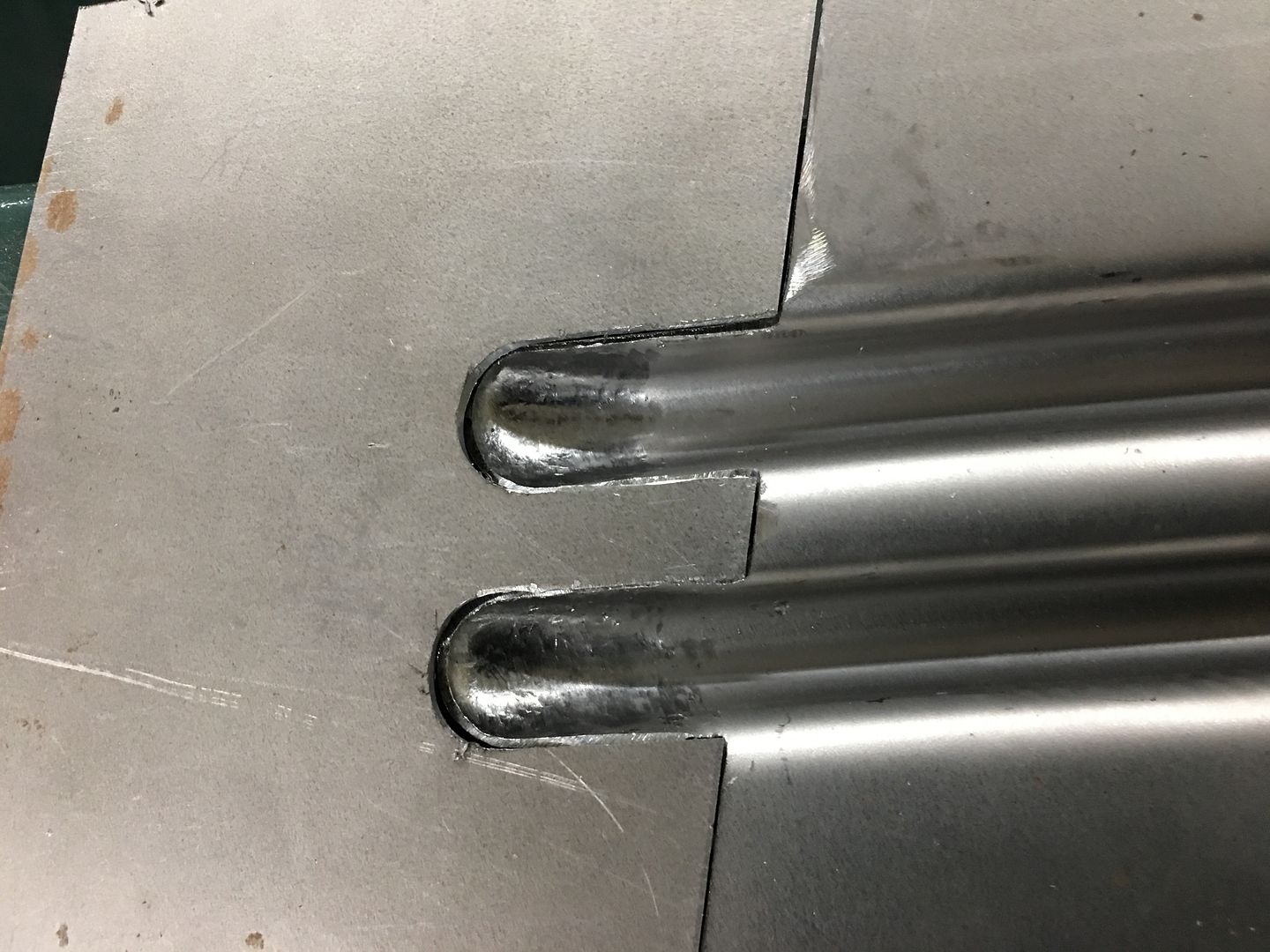
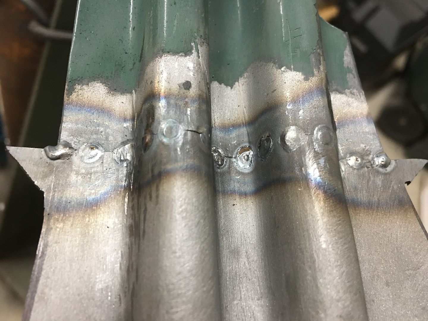
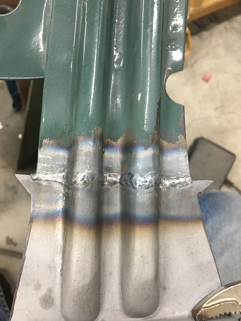
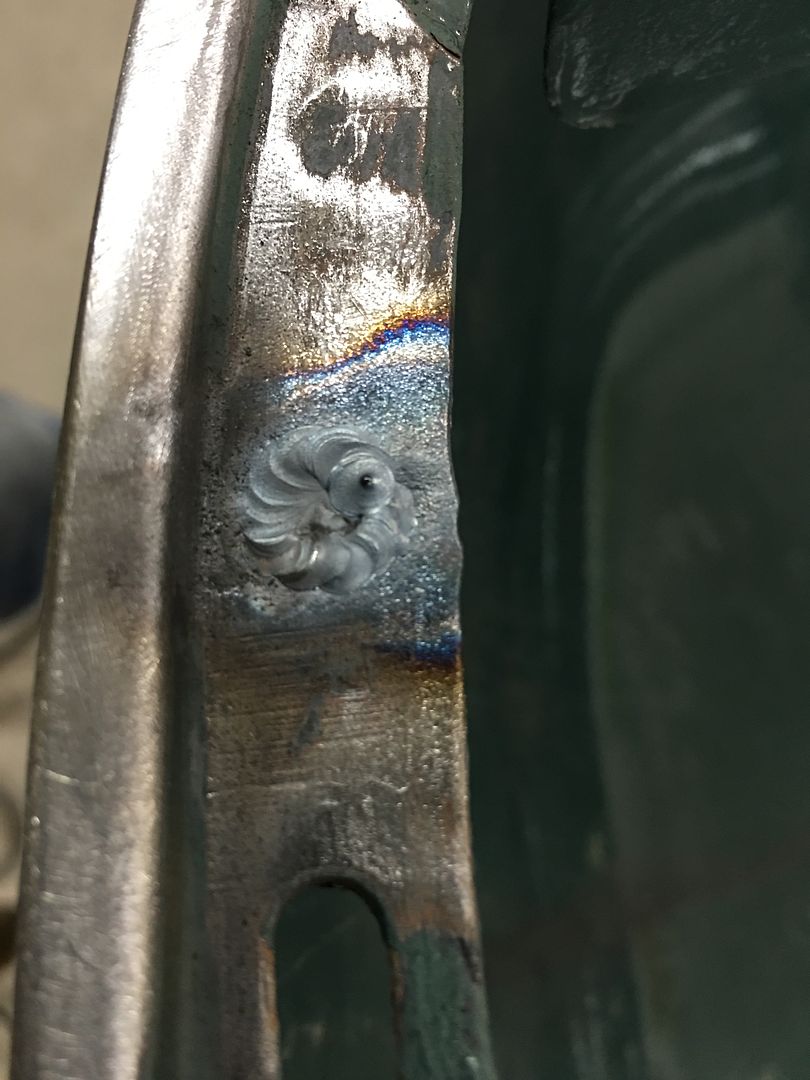
The TIG is used to fully weld the patches in place...
Front side:
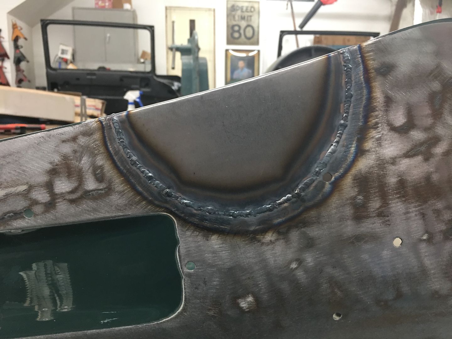
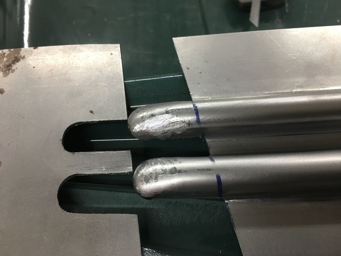
Back side, full penetration on the weld..
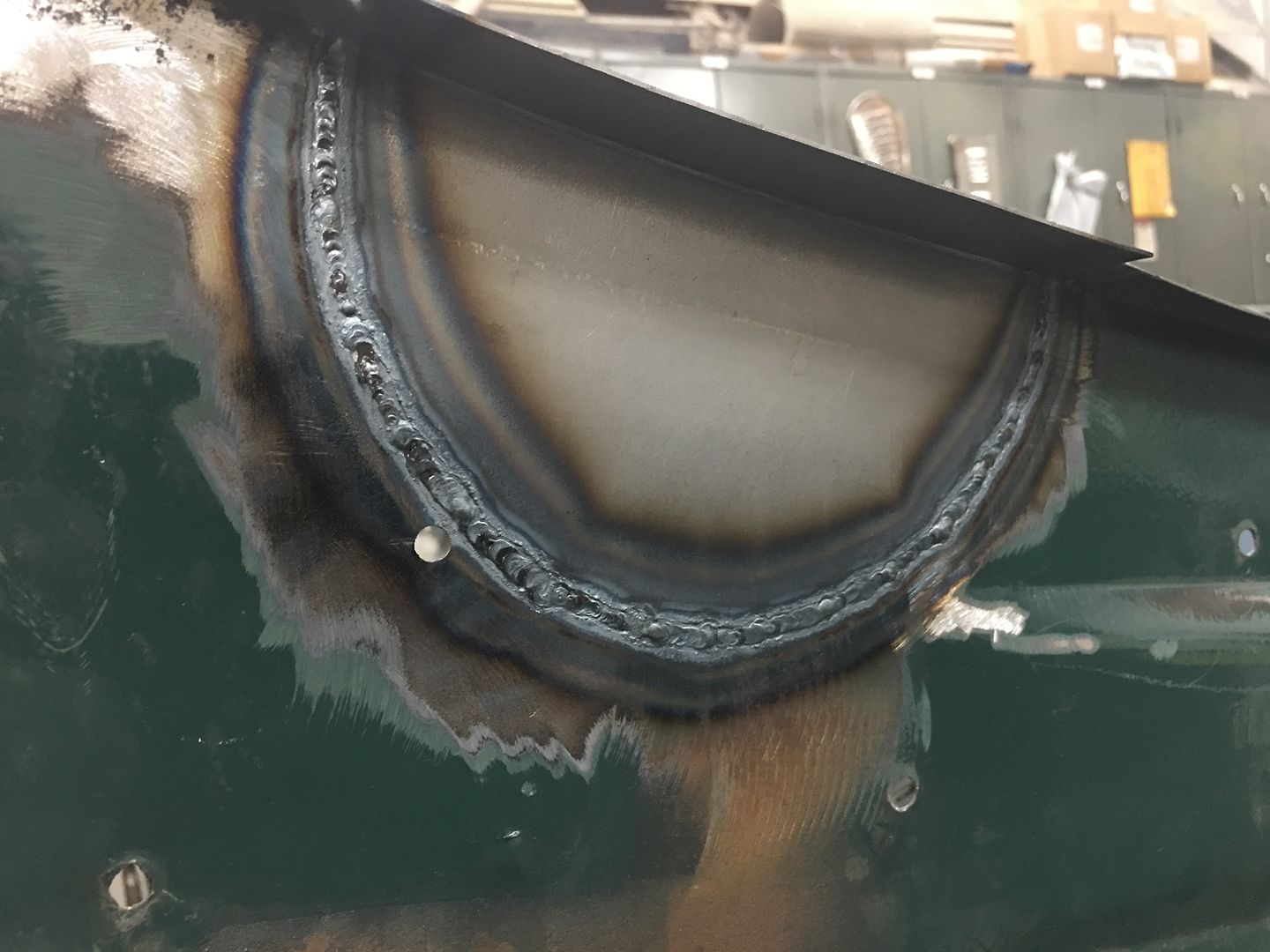
The weld seams are then planished and dressed. Next, the front of the hood had a stress crack adjacent to one of the rubber bumpers. To stabilize the hood prior to cutting out this area, the brace is clamped back in place..
The damaged area is cut out, a "doubler" had been used toward the front to add strength to the area, so care is used to not cut that off..
A replacement patch is cut out, bends added, and tacked in place. A plug weld ties this in with the doubler..
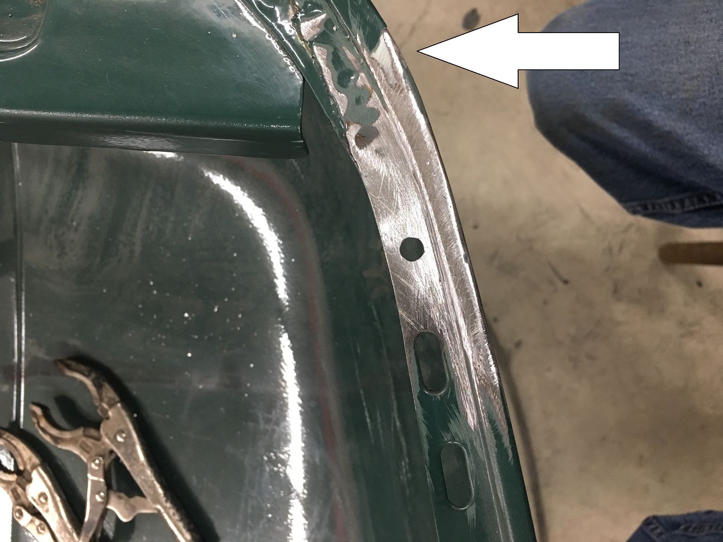
All trimmed and welds dressed, the hood bumper hole is re-drilled in the new patch. Then we notice a bit of filler closer to the nose of the hood (arrow). Let's remove that while we're here to see what carnage lies in wait.
Gotta love this game of dominos..
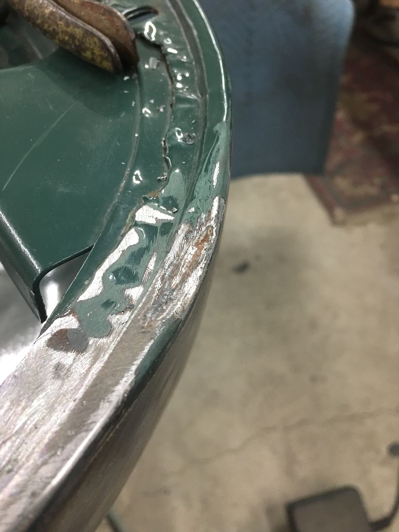
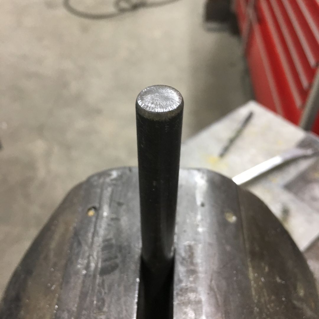
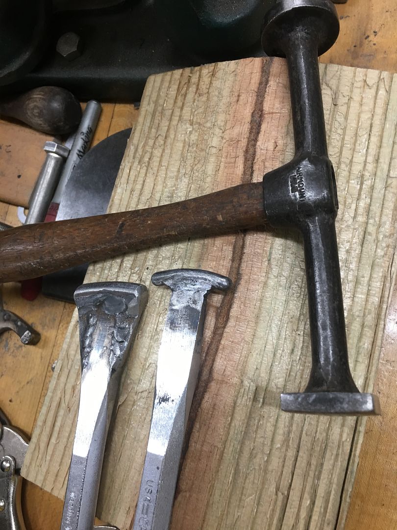
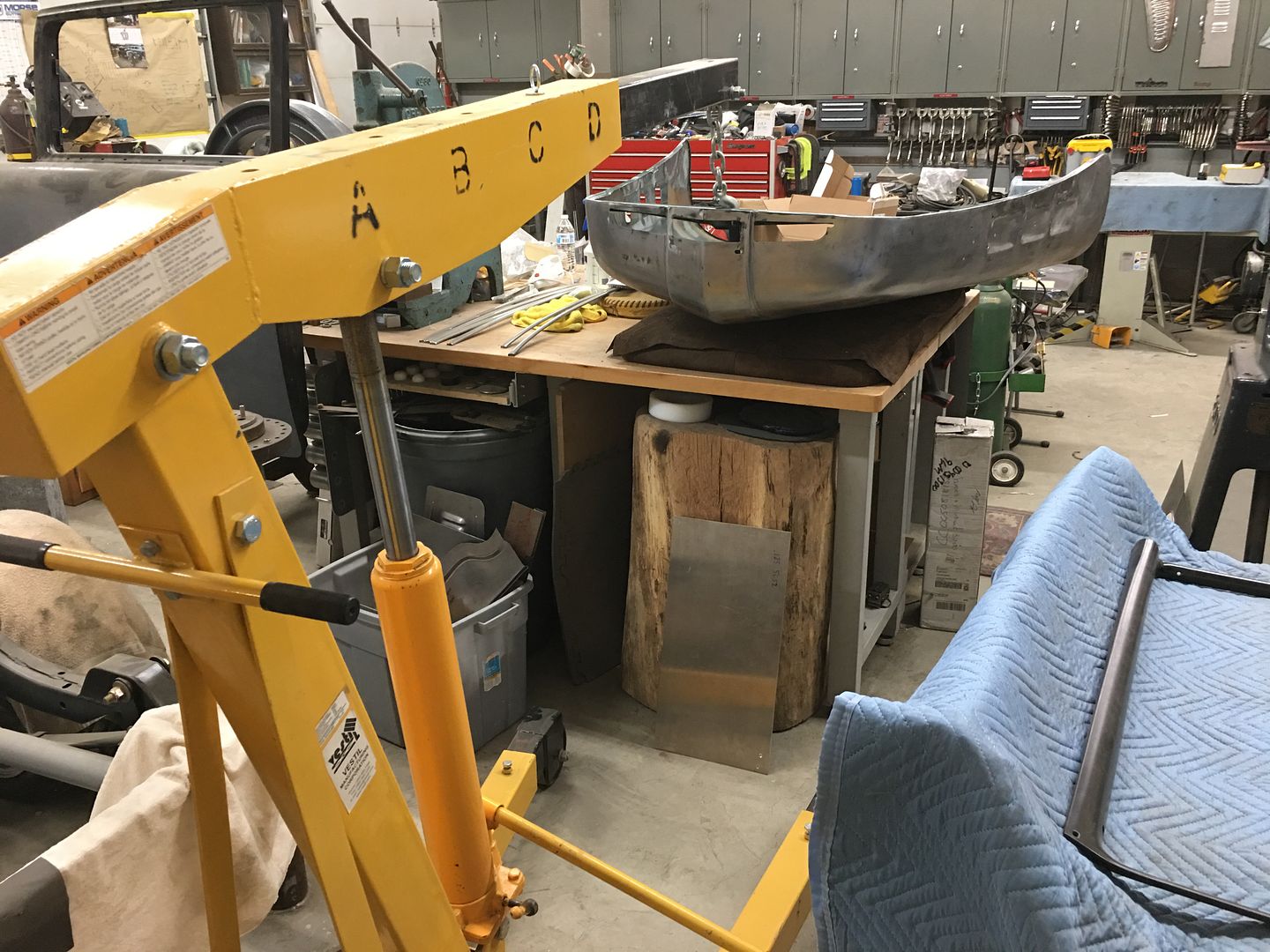
The low area needs to be bumped up, and with little room for swinging hammers, a new tool is in order. Using the South Bend "milling machine" a die is made for the outer portion..
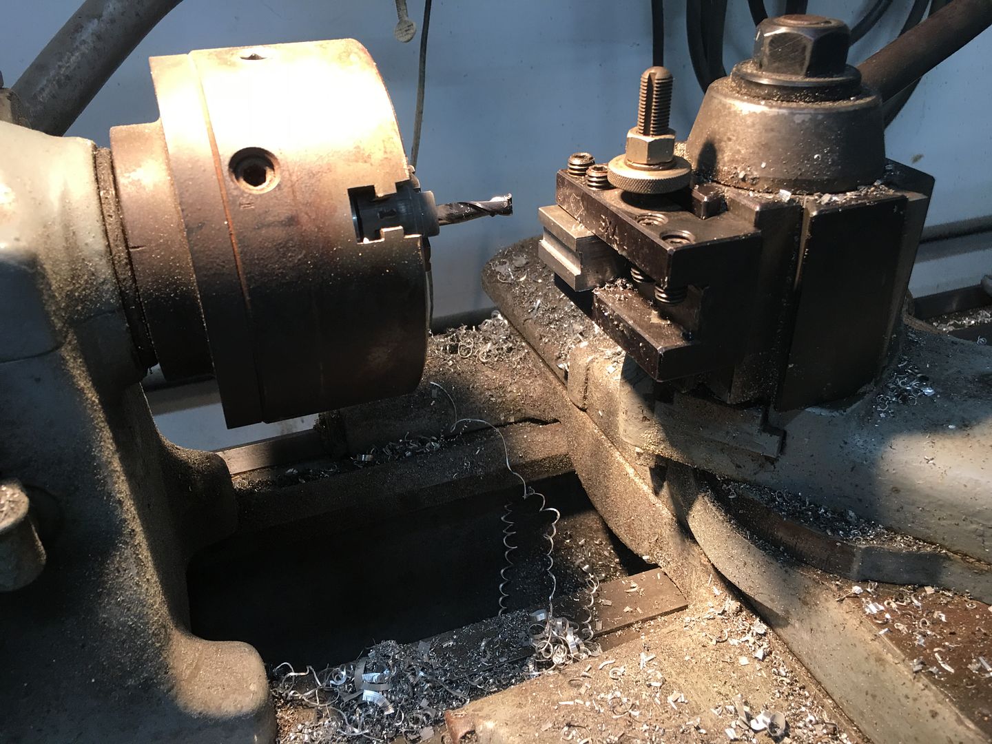
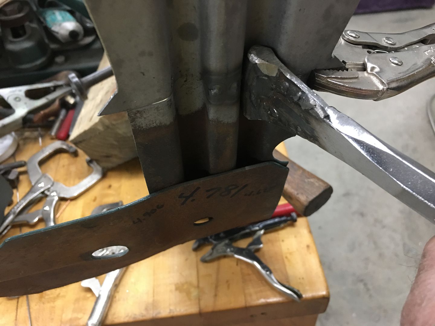
Using a pair of C-clamp vise grips (there goes another pair) the die we made will be welded to one side, the opposite is giving a bit of a trim to better fit in the confines of the slight gap available on the inside..
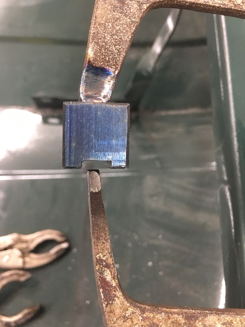
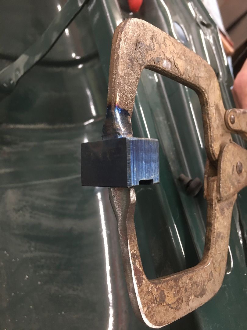
I missed the action shots, but the clamping of the vise grip is used to raise the low areas. Then dressed out for a much better "filler free" lower edge for the hood.
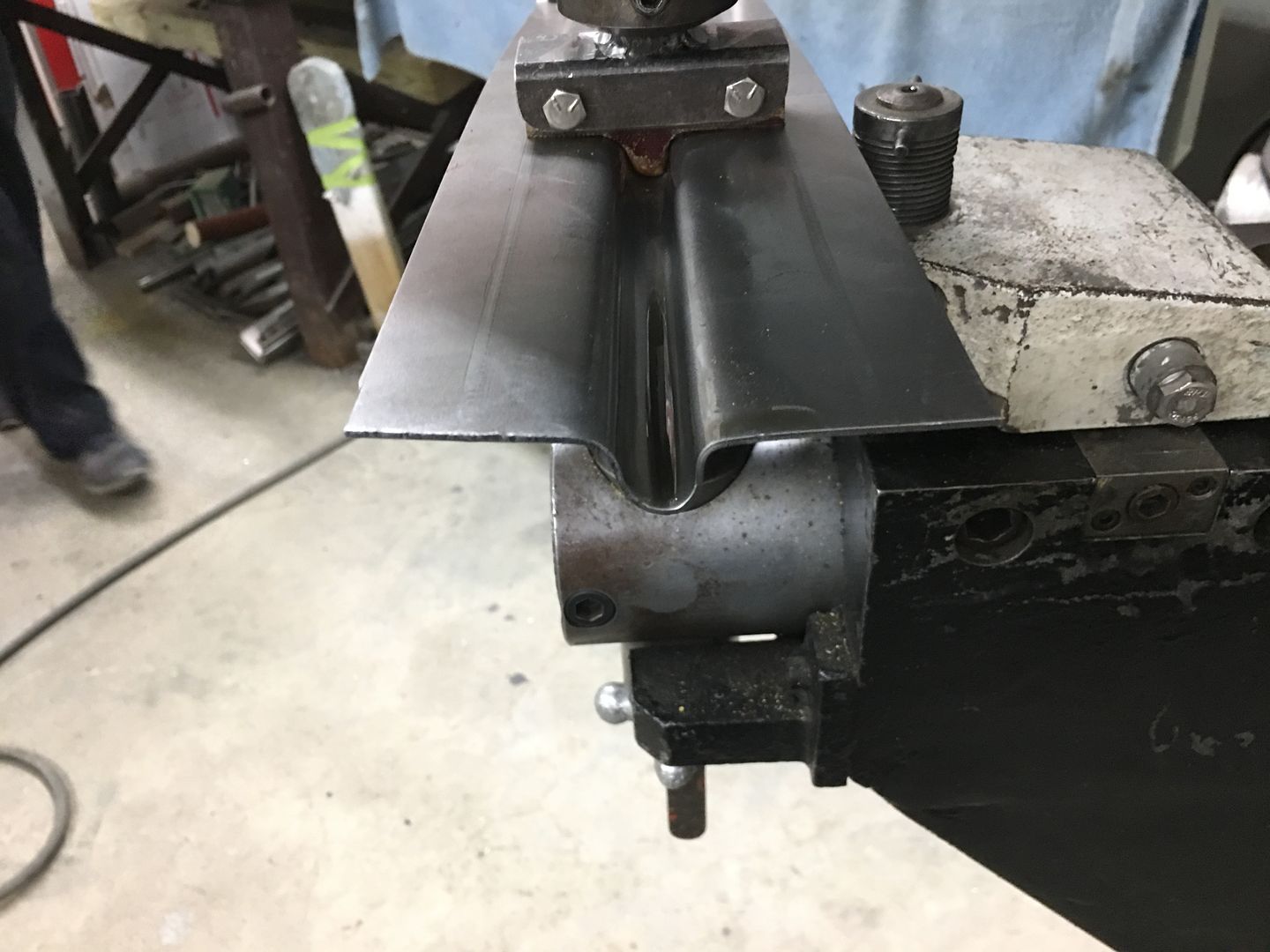
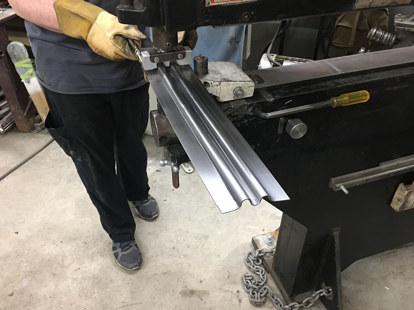
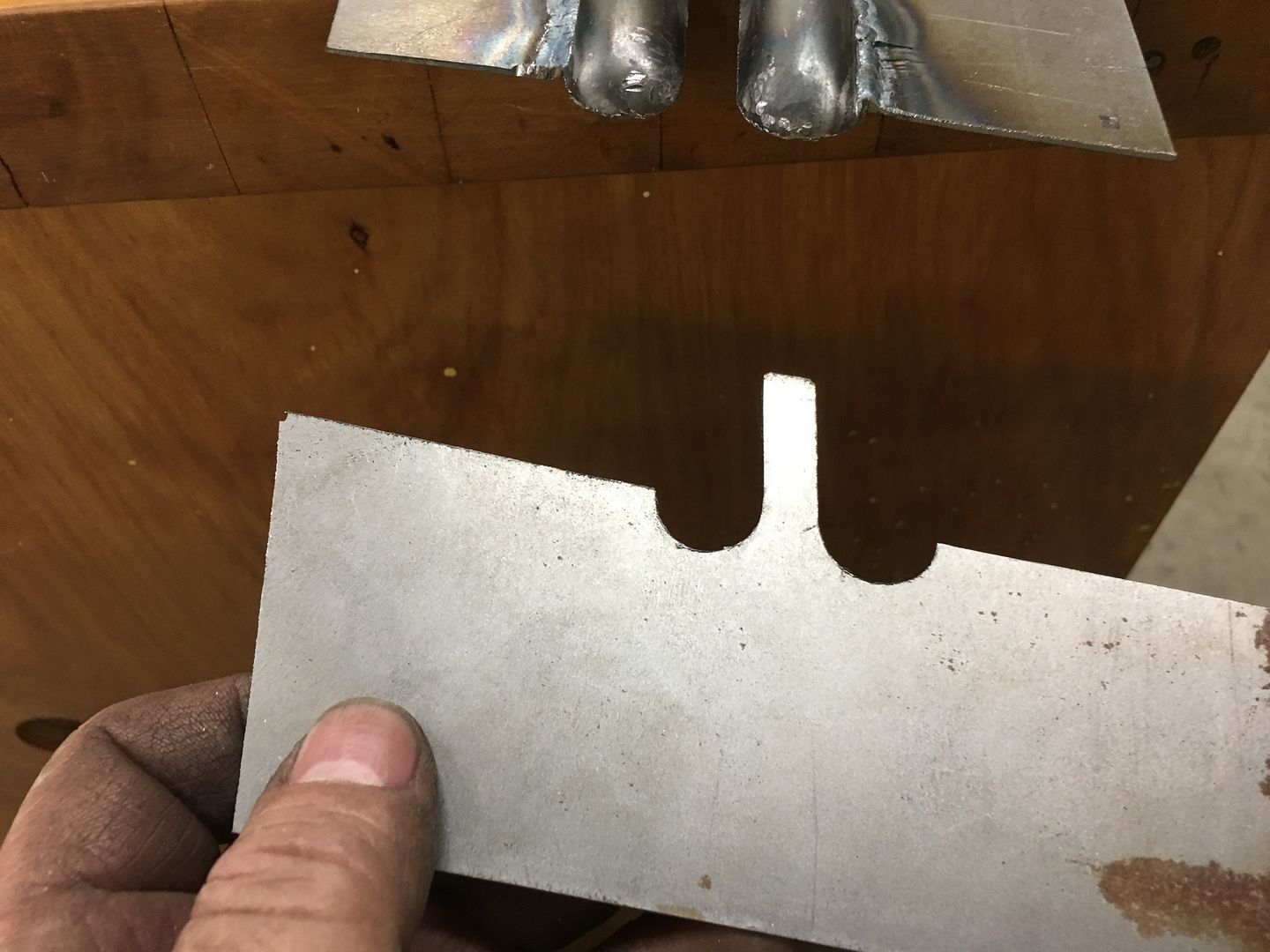
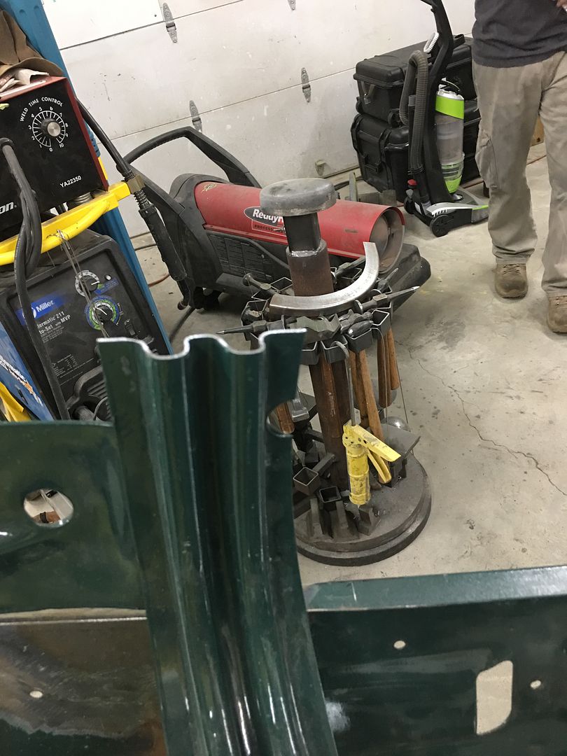
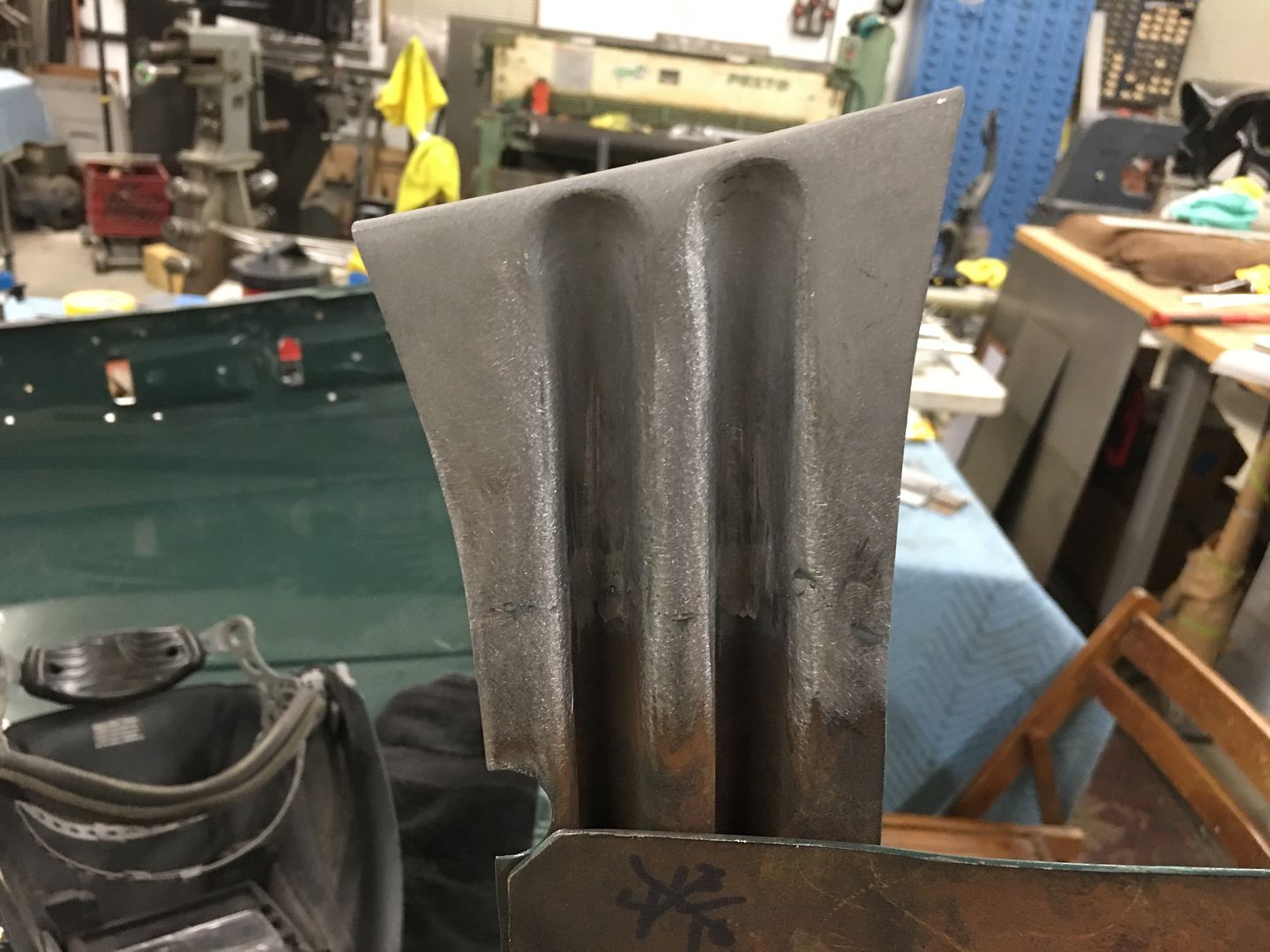
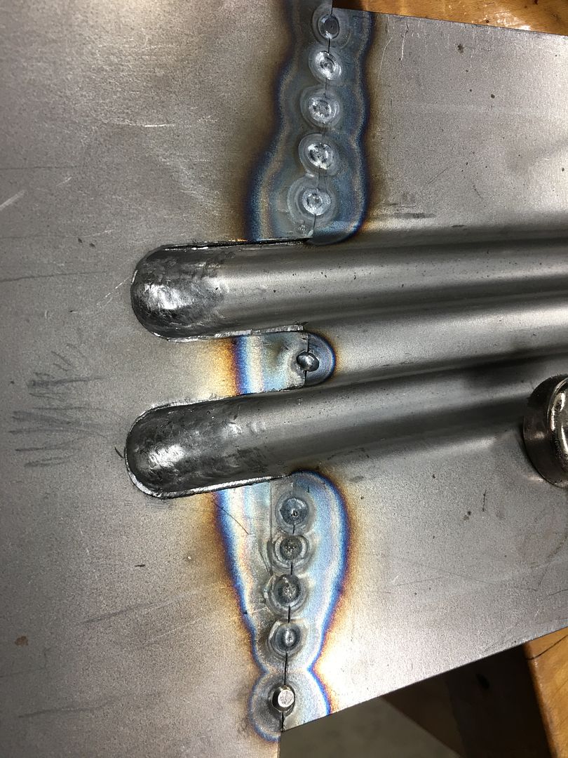
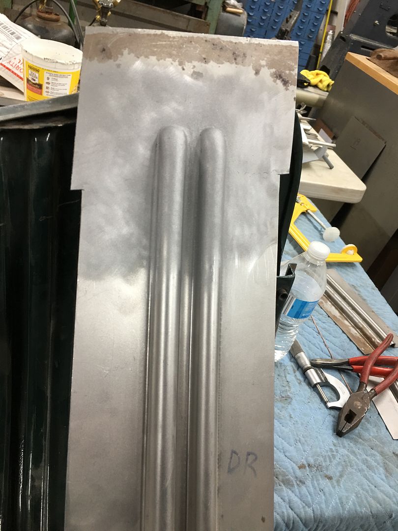
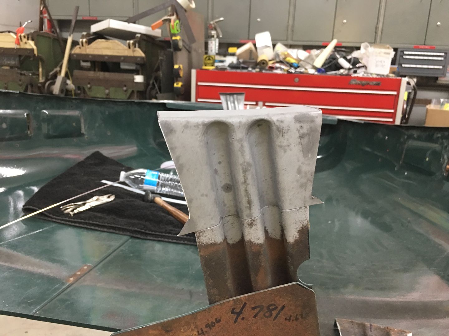
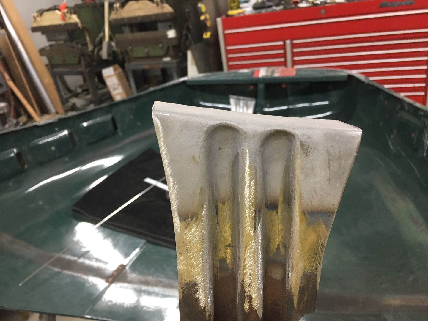
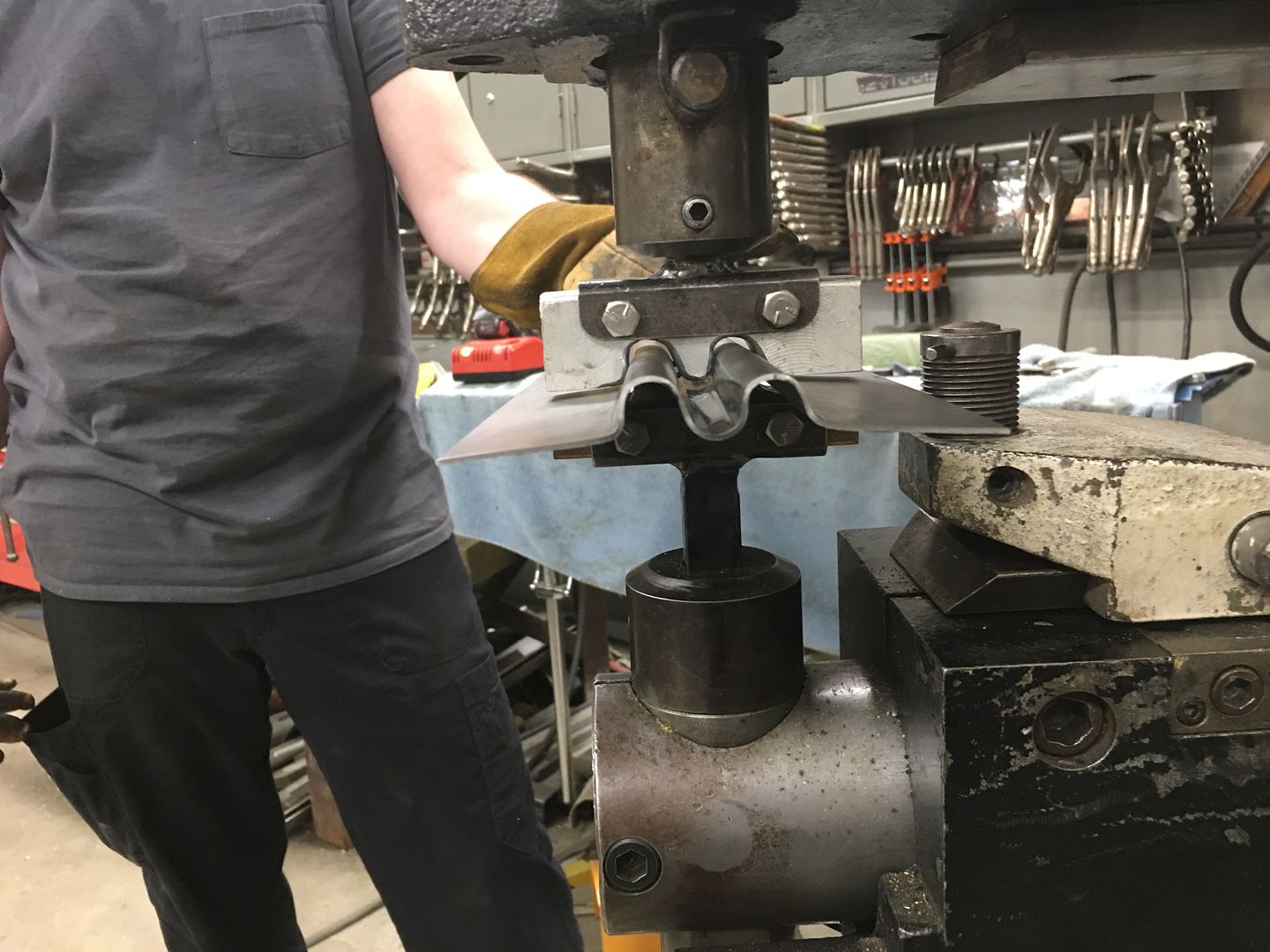
With Mike having completed the dies to duplicate the ribs in the hood brace we did a test run on a piece of 16 Ga cold rolled steel. First upper die addresses middle rib only, way to much drawing going on to expect this out of one set of dies...
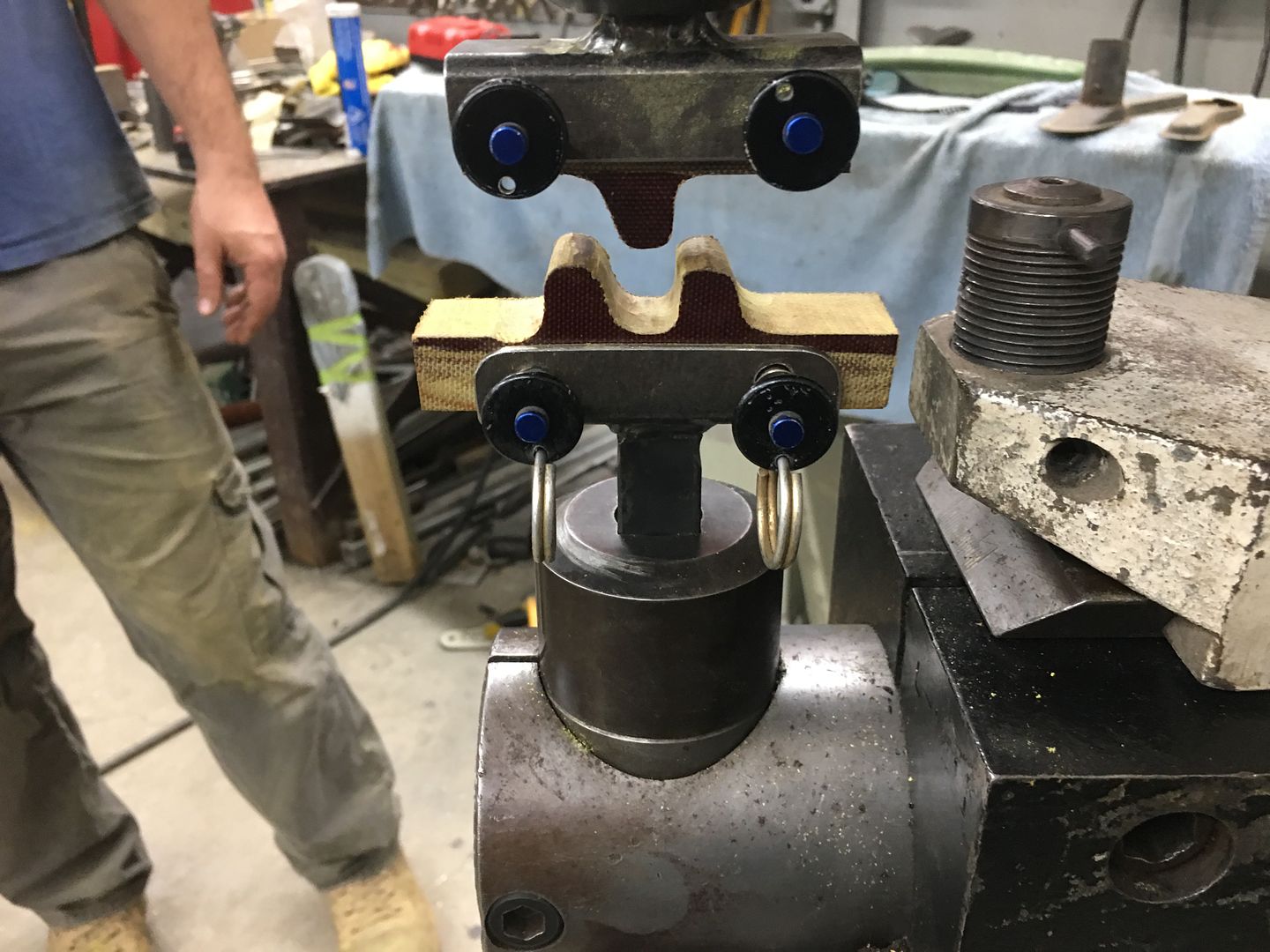
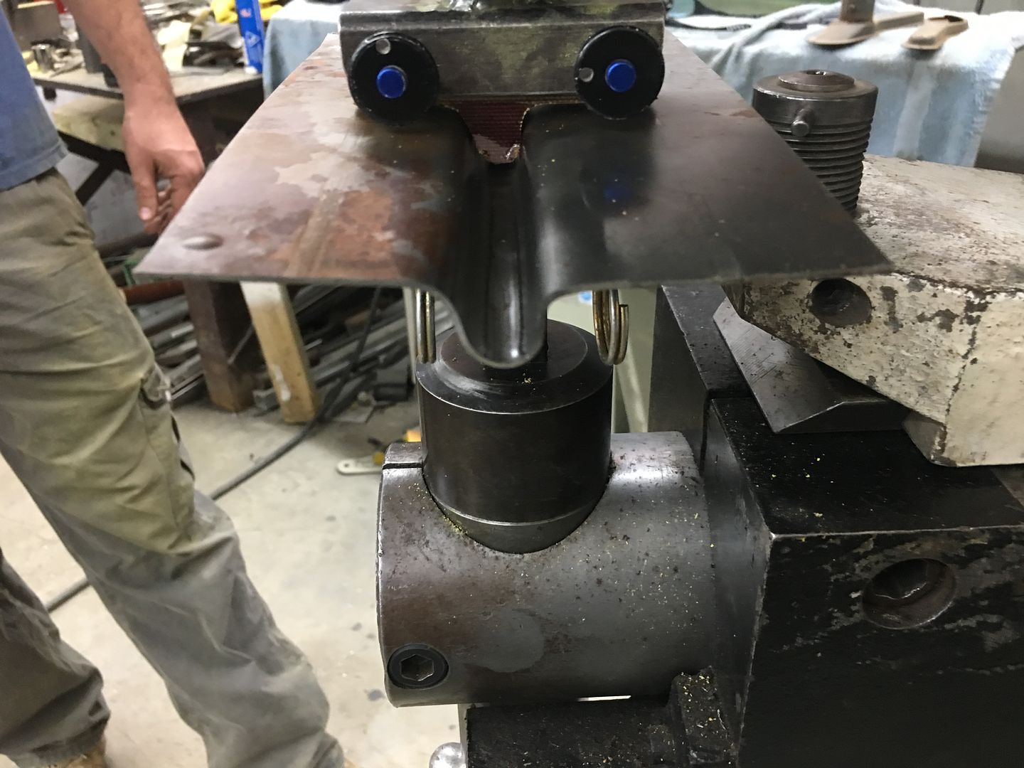
Then top die is changed out for the remainder of the ribs...
A bit of fine tuning needed, but looks like this process will work to repair the rot in the bottom of the brace ends..
The TIG is used to fully weld the patches in place...
Front side:
Back side, full penetration on the weld..
The weld seams are then planished and dressed. Next, the front of the hood had a stress crack adjacent to one of the rubber bumpers. To stabilize the hood prior to cutting out this area, the brace is clamped back in place..
The damaged area is cut out, a "doubler" had been used toward the front to add strength to the area, so care is used to not cut that off..
A replacement patch is cut out, bends added, and tacked in place. A plug weld ties this in with the doubler..
All trimmed and welds dressed, the hood bumper hole is re-drilled in the new patch. Then we notice a bit of filler closer to the nose of the hood (arrow). Let's remove that while we're here to see what carnage lies in wait.
Gotta love this game of dominos..
The low area needs to be bumped up, and with little room for swinging hammers, a new tool is in order. Using the South Bend "milling machine" a die is made for the outer portion..
Using a pair of C-clamp vise grips (there goes another pair) the die we made will be welded to one side, the opposite is giving a bit of a trim to better fit in the confines of the slight gap available on the inside..
I missed the action shots, but the clamping of the vise grip is used to raise the low areas. Then dressed out for a much better "filler free" lower edge for the hood.
With Mike having completed the dies to duplicate the ribs in the hood brace we did a test run on a piece of 16 Ga cold rolled steel. First upper die addresses middle rib only, way to much drawing going on to expect this out of one set of dies...
Then top die is changed out for the remainder of the ribs...
A bit of fine tuning needed, but looks like this process will work to repair the rot in the bottom of the brace ends..
Thread Starter
|
Tuned
Joined: Aug 2007
Posts: 457
Likes: 115
From: Maryland
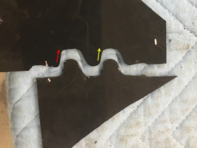
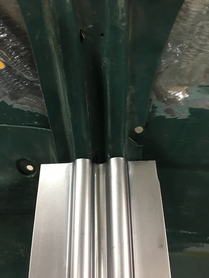
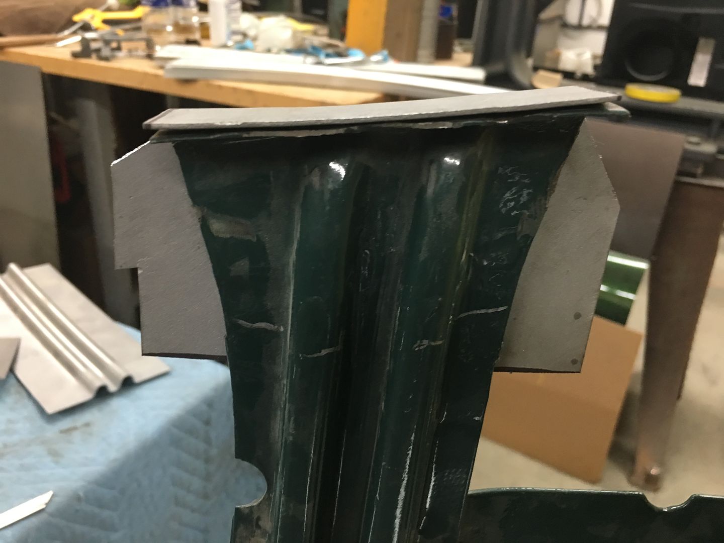
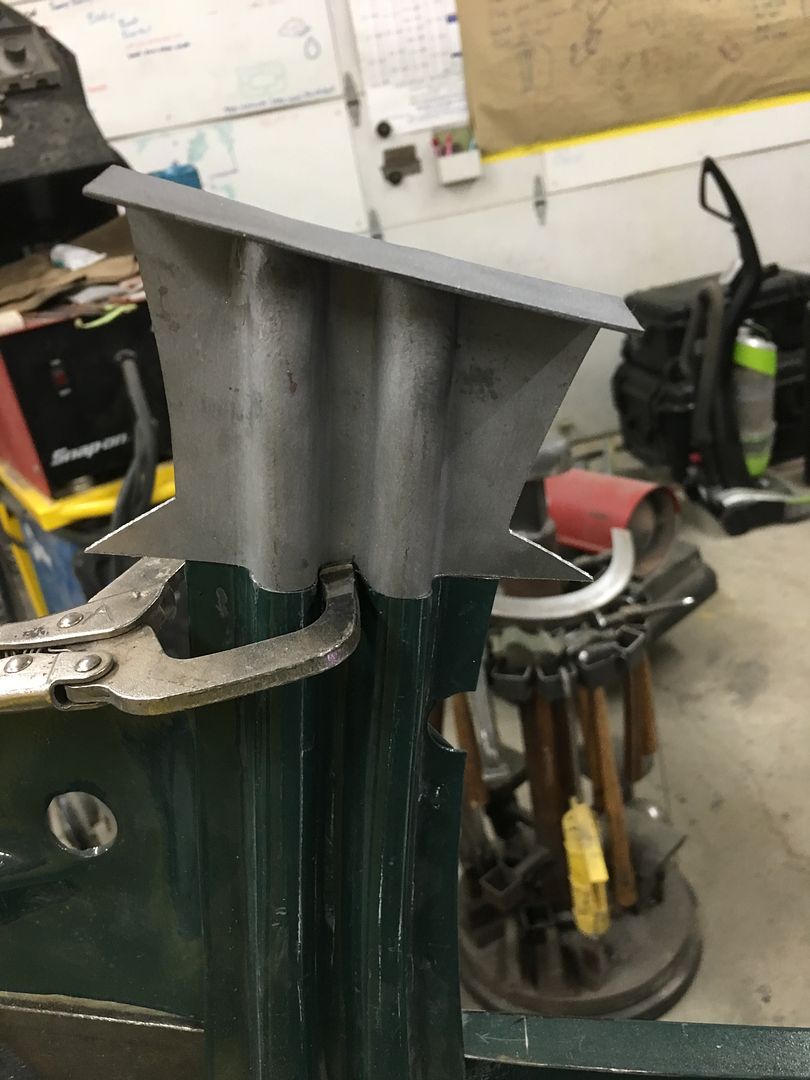
Now to fine tune our dies for the hood brace. Looking at our original profile template, the first upsweep (red arrow) and second upsweep (yellow arrow) are both nearly vertical as compared to the opposite side.
Our first test run shows the first upsweep spread too wide, not enough vertical...
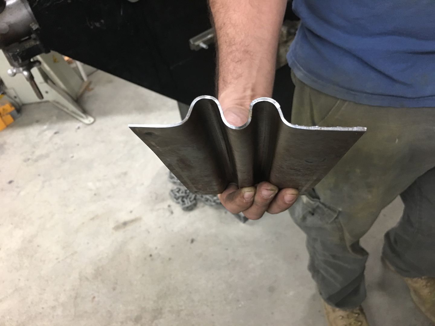
Looking at the die that was made, a bit too much material was removed such that this vertical feature was lost...
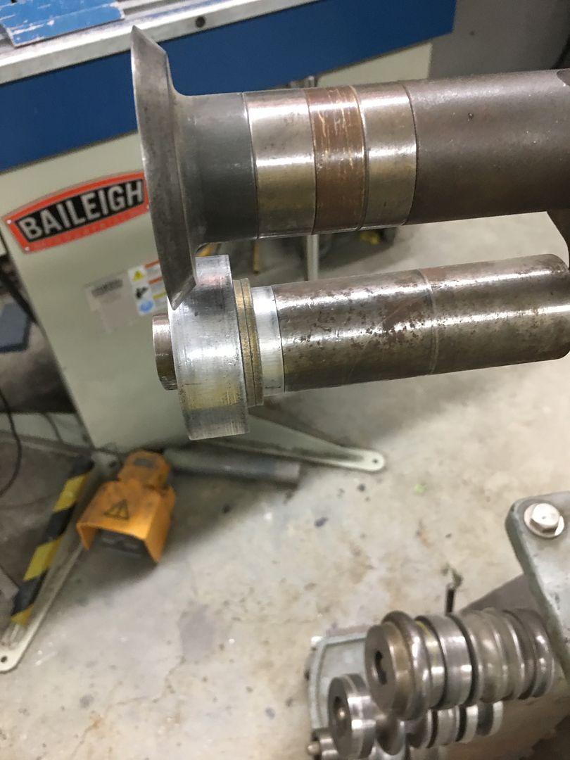
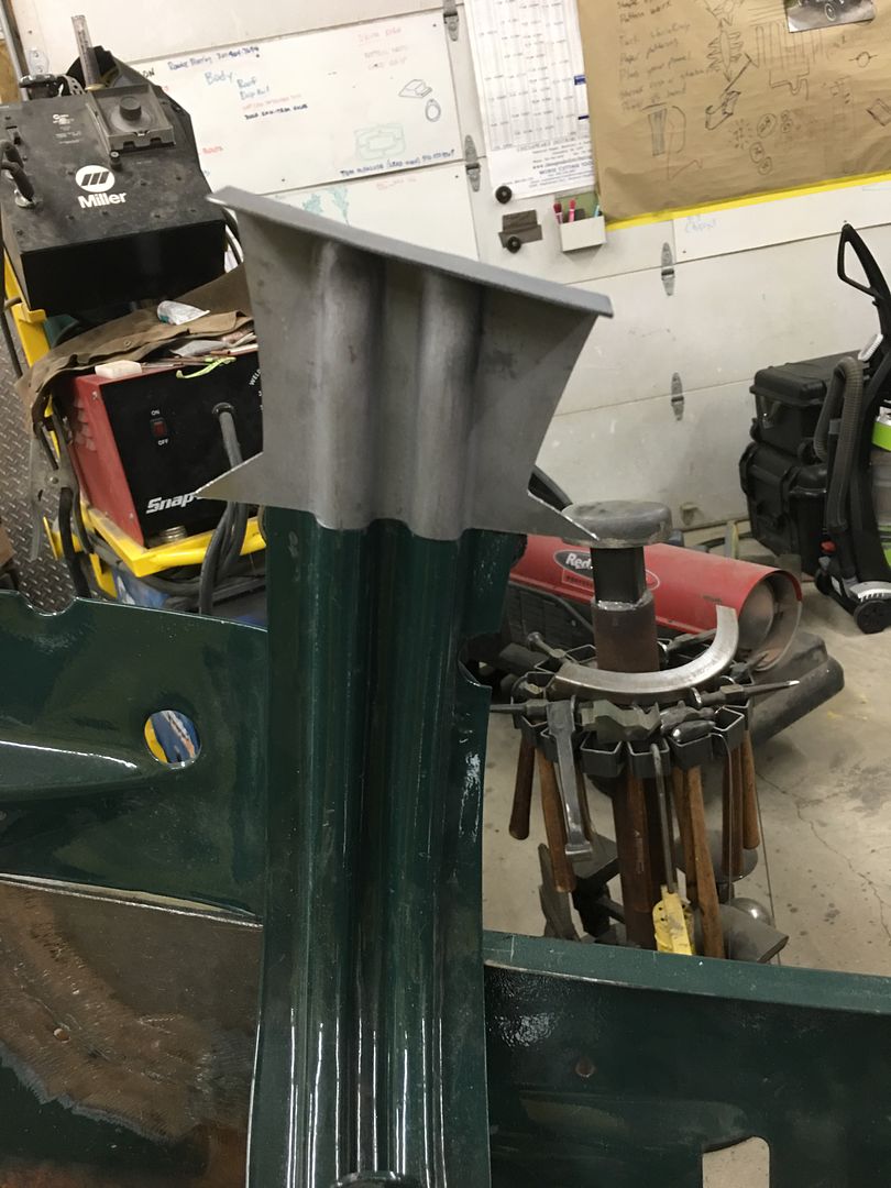
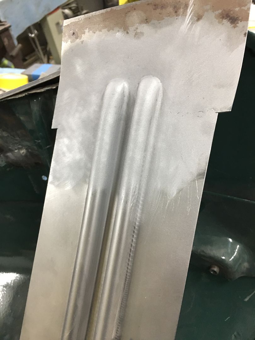
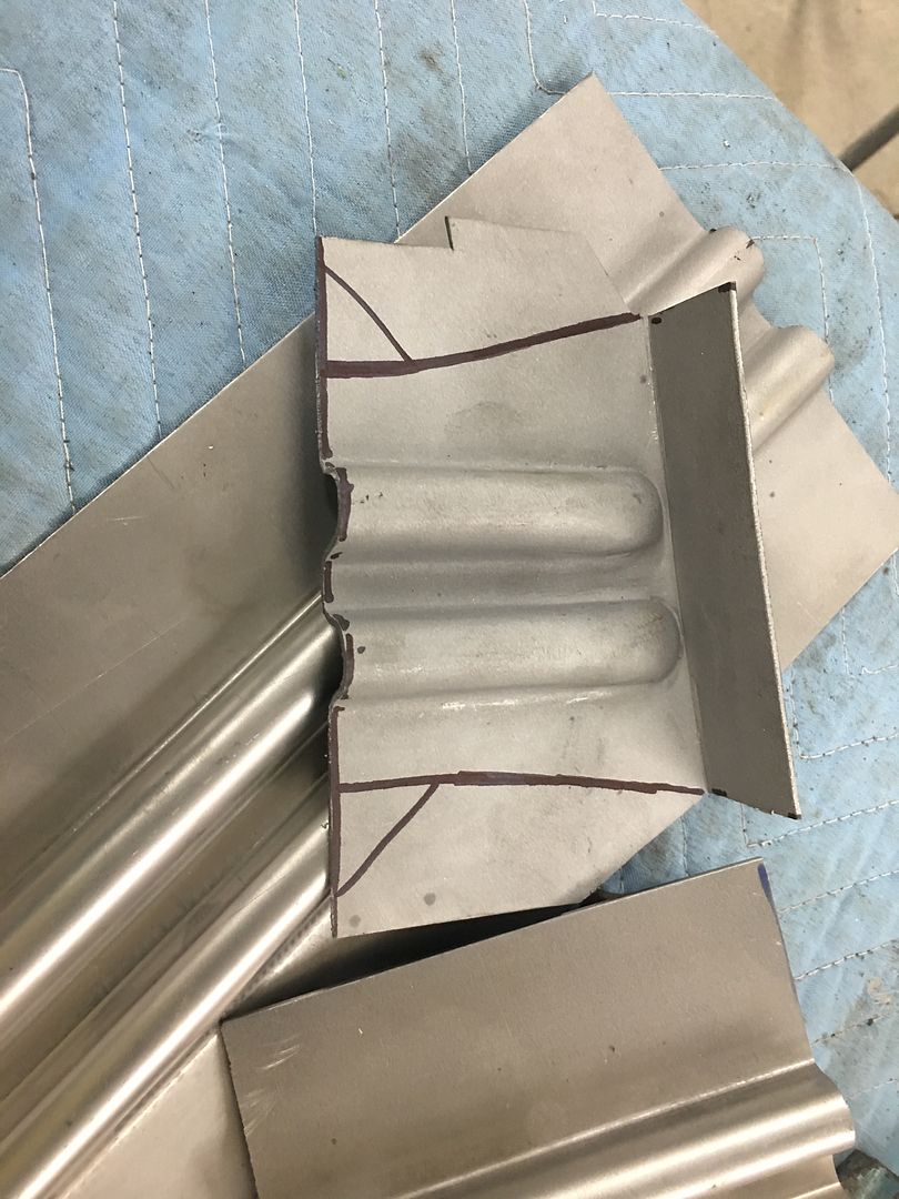
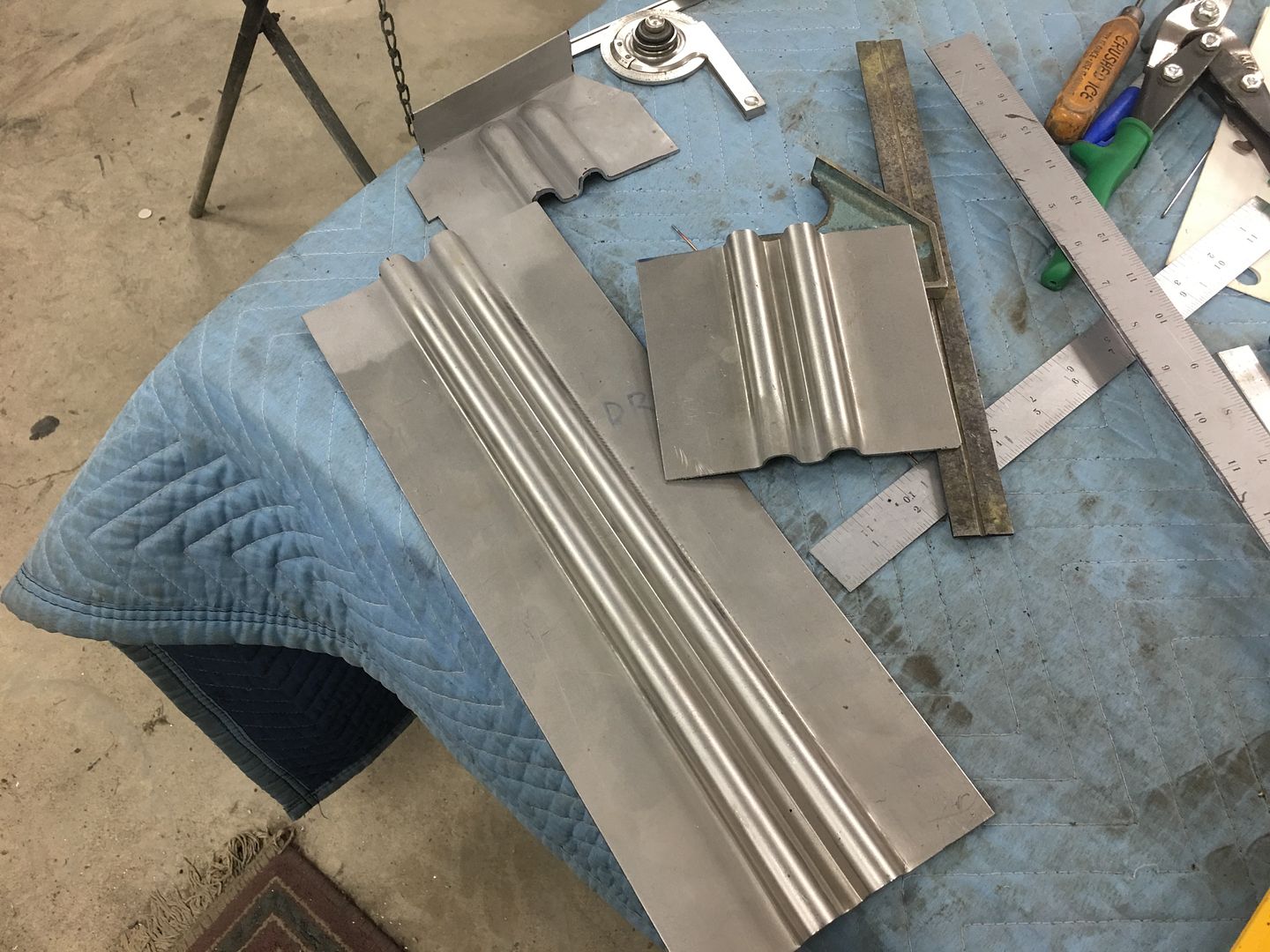
So a new die was made for the top, this time out of aluminum. The phenolic is somewhat easy to cut out but does have challenges in making crisp bend details, so lets see if the aluminum helps out..
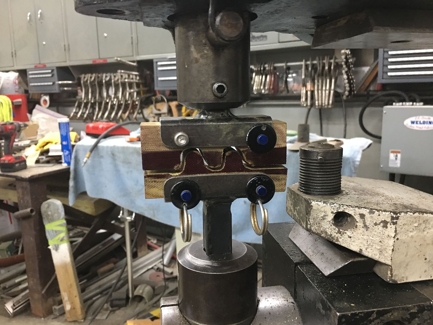
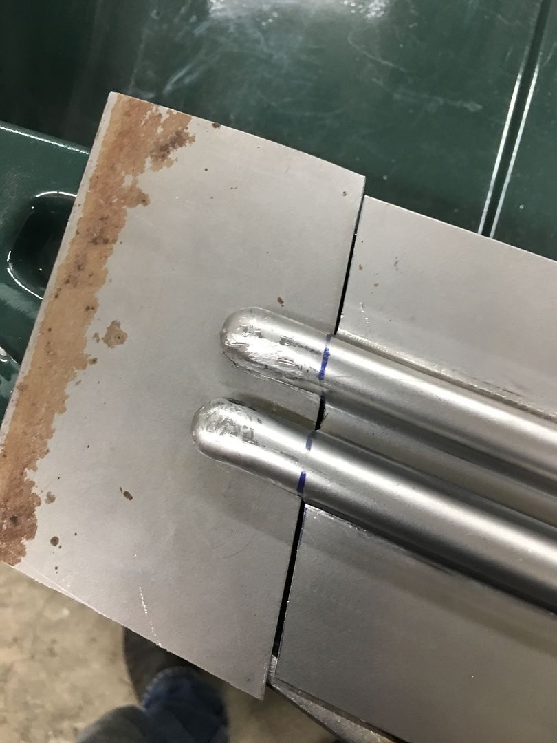
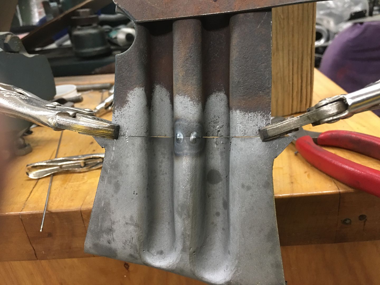
Next run, this time we'll do two panels in case they work... First pass to draw the metal into the center rib...
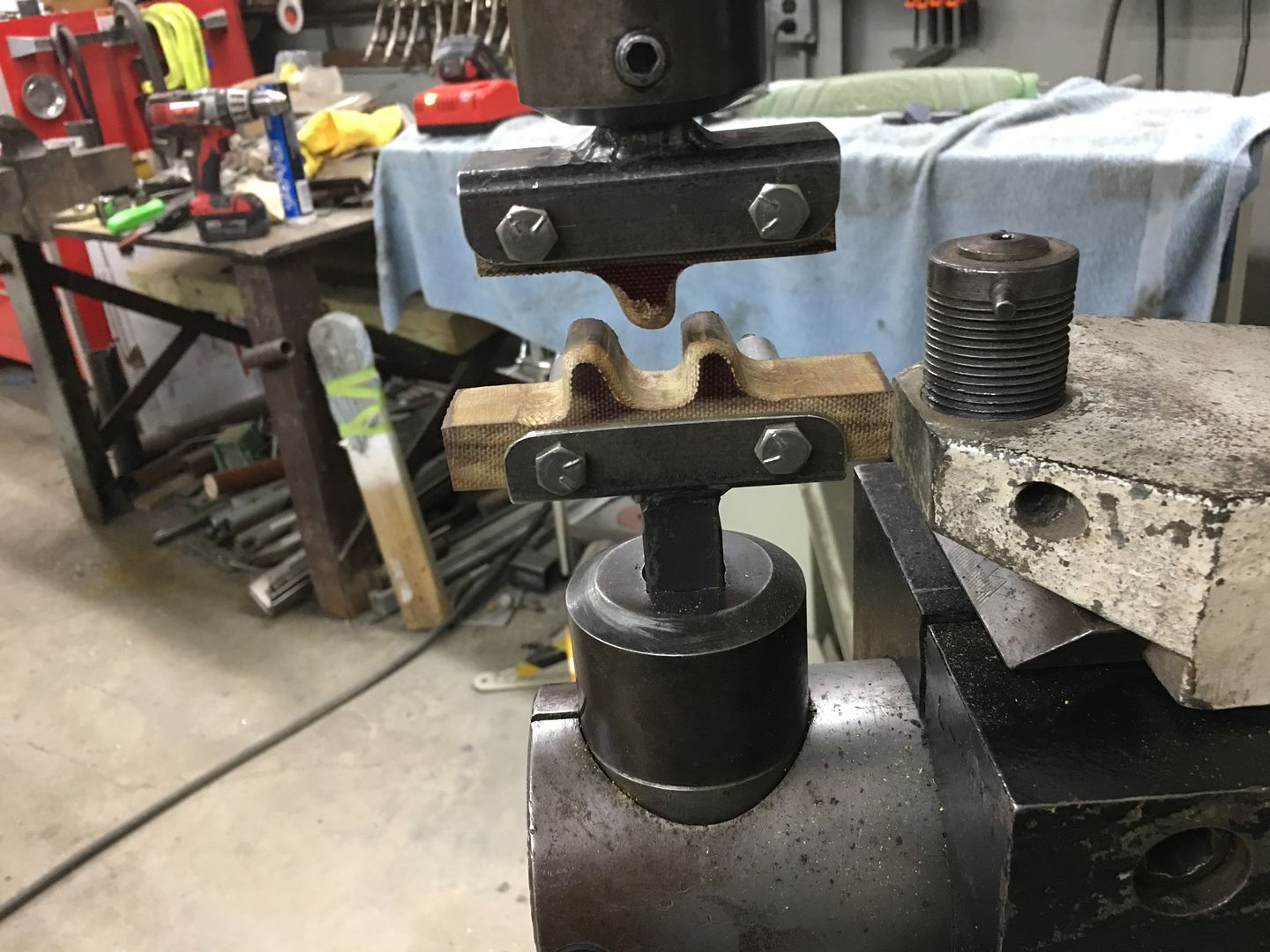
This is about 8 passes, each progressively deeper. The circle fixture to the right in the picture (white base) is used as a back stop to keep our rib centered.
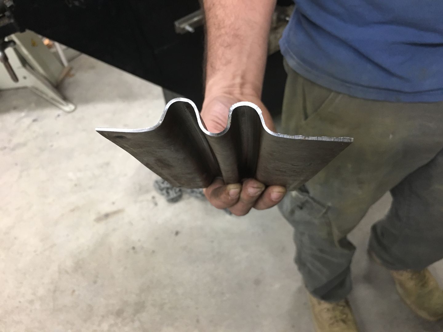
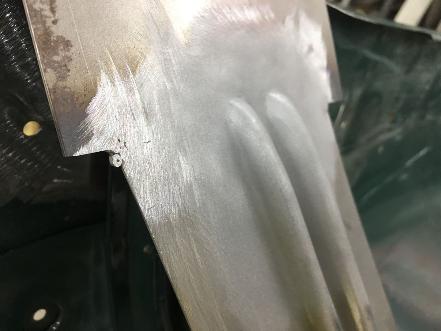
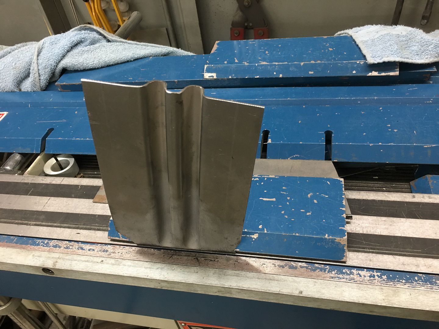
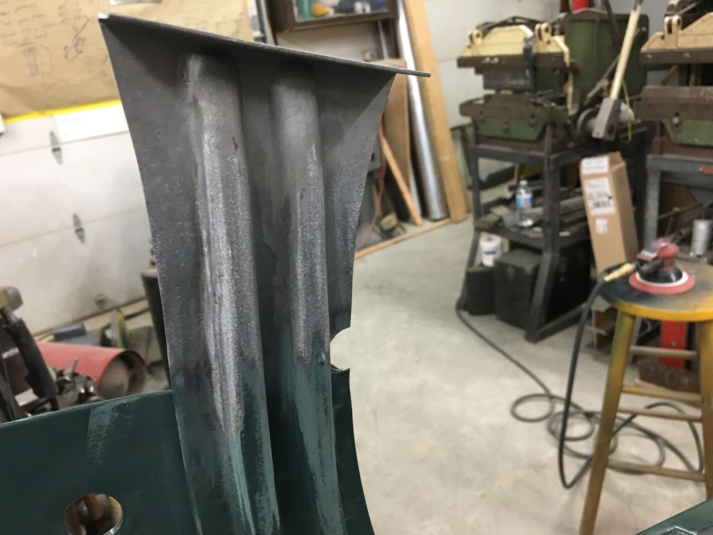
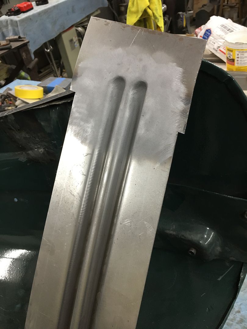
This is about 9/16 of depth, so quite a bit of draw.. Next, the new top die is added and goes through the same 8 progressive passes.. Note in the next picture the vertical upsweeps are both nearly vertical. Success!

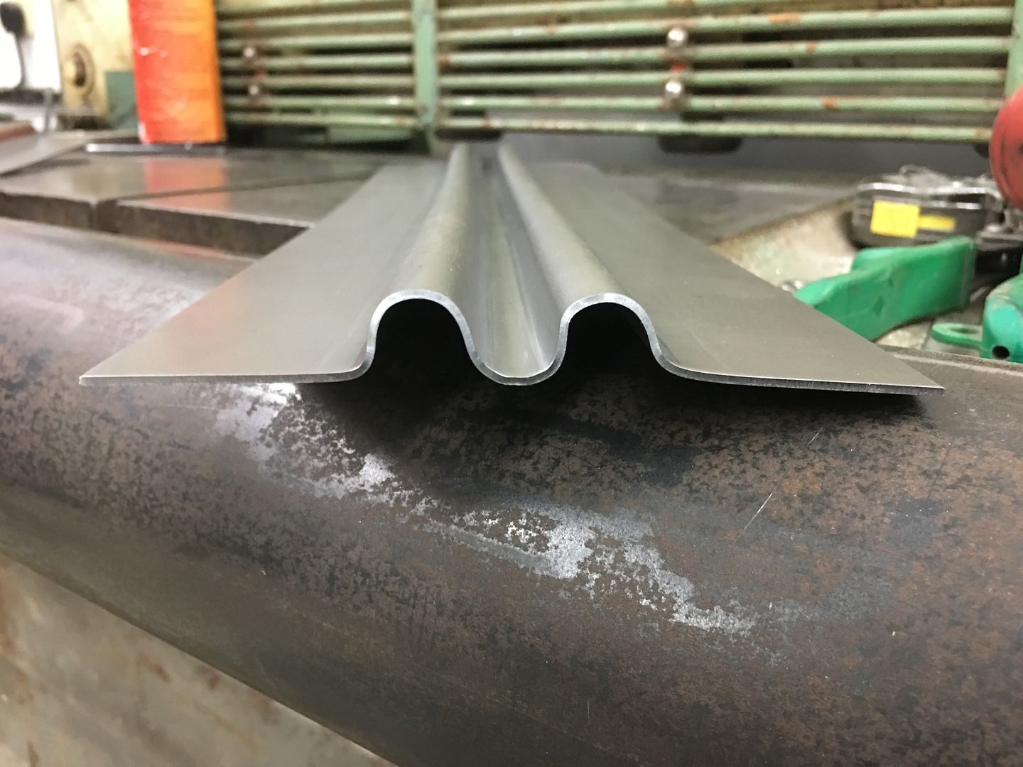
Matching up to the original, this looks like the right replacement.
video version:
.
Our first test run shows the first upsweep spread too wide, not enough vertical...
Looking at the die that was made, a bit too much material was removed such that this vertical feature was lost...
So a new die was made for the top, this time out of aluminum. The phenolic is somewhat easy to cut out but does have challenges in making crisp bend details, so lets see if the aluminum helps out..
Next run, this time we'll do two panels in case they work... First pass to draw the metal into the center rib...
This is about 8 passes, each progressively deeper. The circle fixture to the right in the picture (white base) is used as a back stop to keep our rib centered.
This is about 9/16 of depth, so quite a bit of draw.. Next, the new top die is added and goes through the same 8 progressive passes.. Note in the next picture the vertical upsweeps are both nearly vertical. Success!
Matching up to the original, this looks like the right replacement.
video version:
.
Thread Starter
|
Tuned
Joined: Aug 2007
Posts: 457
Likes: 115
From: Maryland
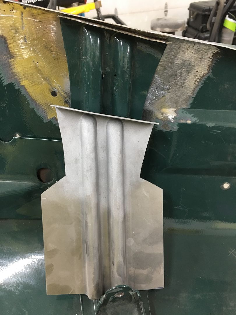
Progress on the hood, the bead details in the brace are offset on the ends to match the hood opening flange. So we use a Vernier protractor to find the angle, and transfer that to our panel. This is where the transition of the taper starts..
Once tapered, the excess is removed from the bottom side and the outer seams TIG welded in place.
A piece of round stock has a radius added to serve as a hammer form for the beads. They are hammered around and excess removed from the back side..
A piece of 16 gauge cold rolled steel is trimmed to fit and TIG welded in place.
Welds dressed and media blasted..
The bend line is transposed from the original. As this bend is slightly convex, it was started using a tipping wheel on the bead roller to a 45* angle, and then finished on the mag brake.
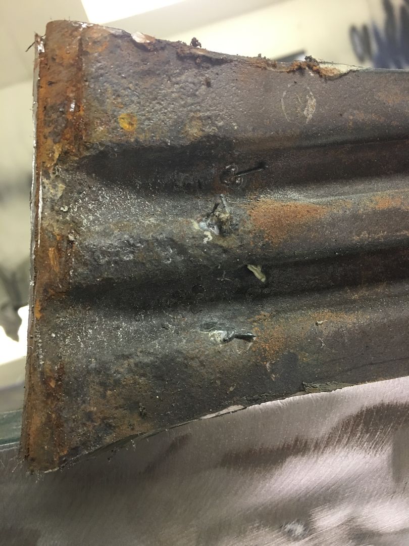
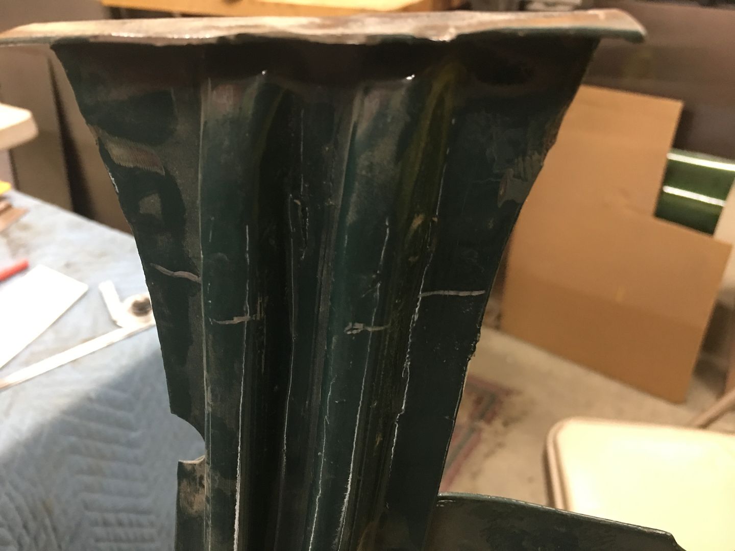
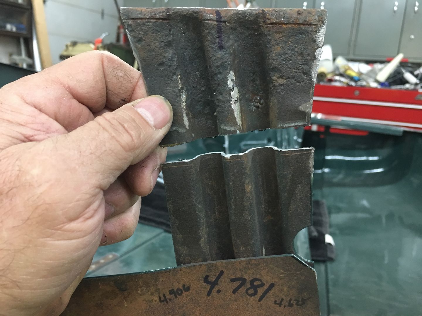
A reminder of the carnage we are repairing:
A profile template is made prior to cutting out the old....
Once tapered, the excess is removed from the bottom side and the outer seams TIG welded in place.
A piece of round stock has a radius added to serve as a hammer form for the beads. They are hammered around and excess removed from the back side..
A piece of 16 gauge cold rolled steel is trimmed to fit and TIG welded in place.
Welds dressed and media blasted..
The bend line is transposed from the original. As this bend is slightly convex, it was started using a tipping wheel on the bead roller to a 45* angle, and then finished on the mag brake.
A reminder of the carnage we are repairing:
A profile template is made prior to cutting out the old....
Thread Starter
|
Tuned
Joined: Aug 2007
Posts: 457
Likes: 115
From: Maryland
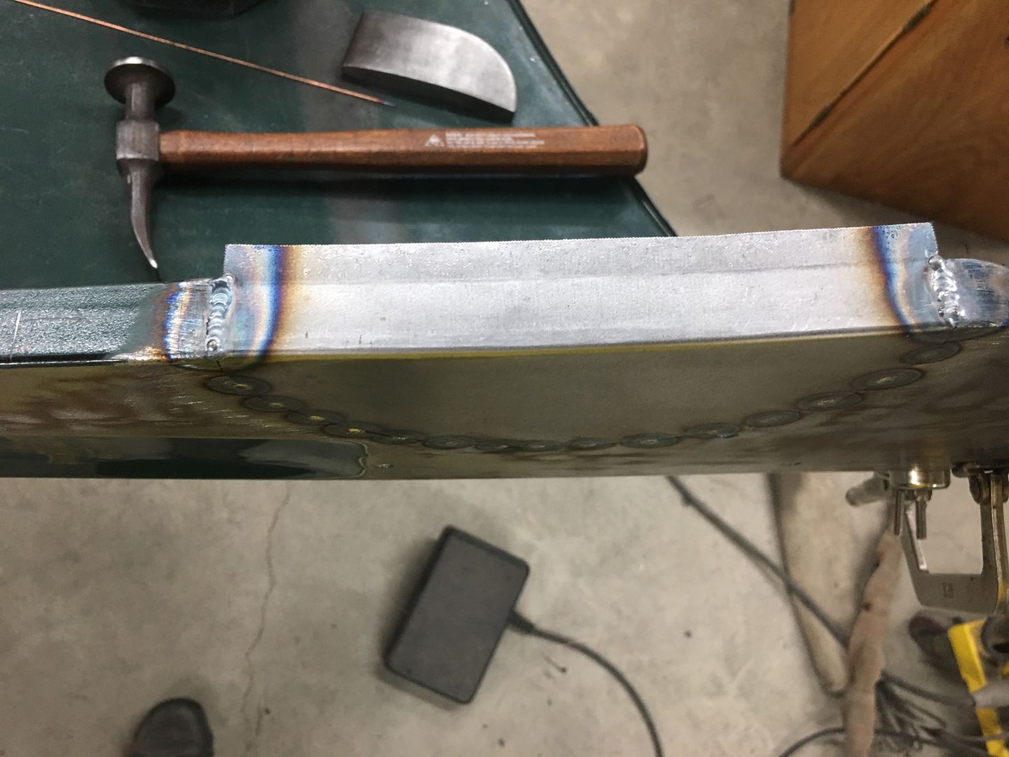
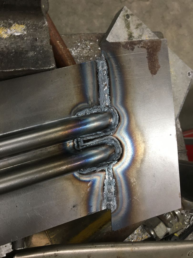
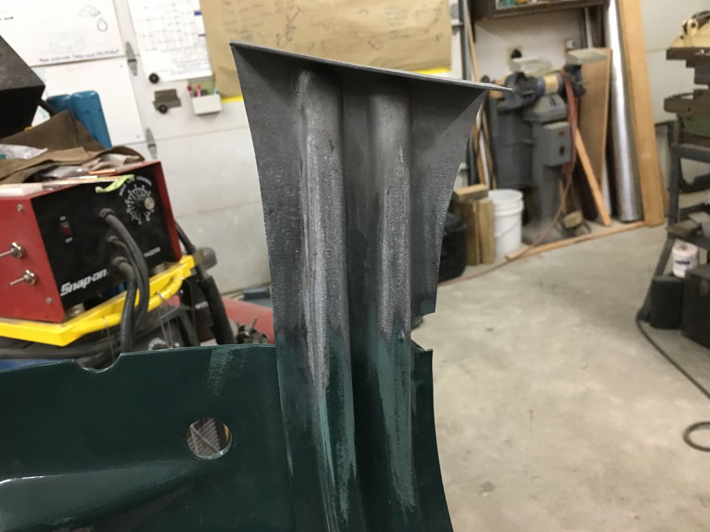
Time to get the hood brace end welded in place. The overall measurement had been taken prior to cutting off the old one, down to the 14 gauge outer plate as a reference. So the new end is trimmed to match this dimension, then held in place with rare earth magnets. The center (inside) rib is aligned and tacked using the TIG....
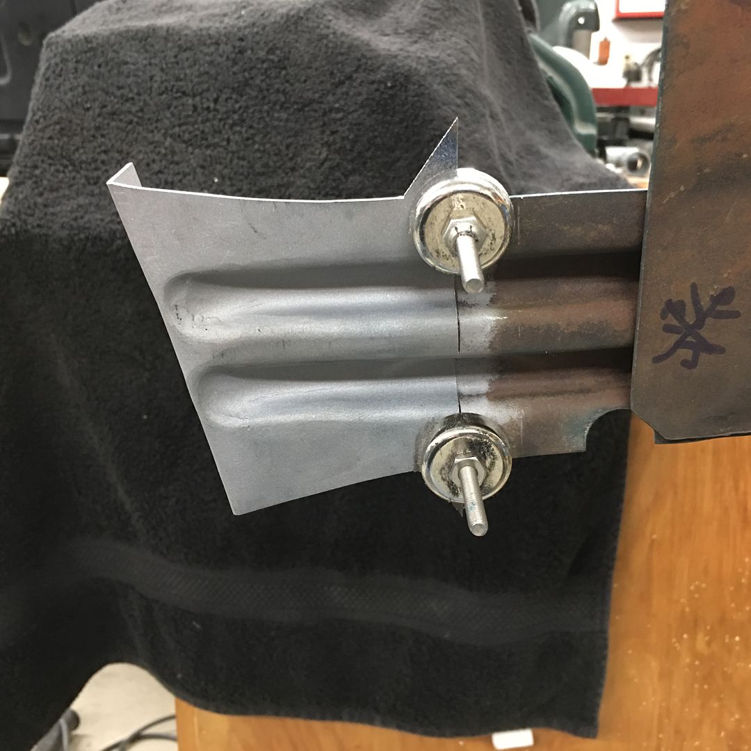
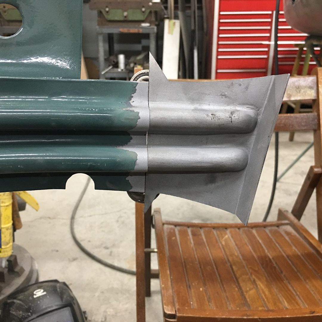
Working outward, the panel surfaces are aligned and tacked as we go. Note the "batwings" left on the outside of the new brace end (yellow arrows). This will act as a heat sink when we make the outer tacks. Had these been trimmed to match prior to welding, the edge will have a tendency to burn back from the heat.
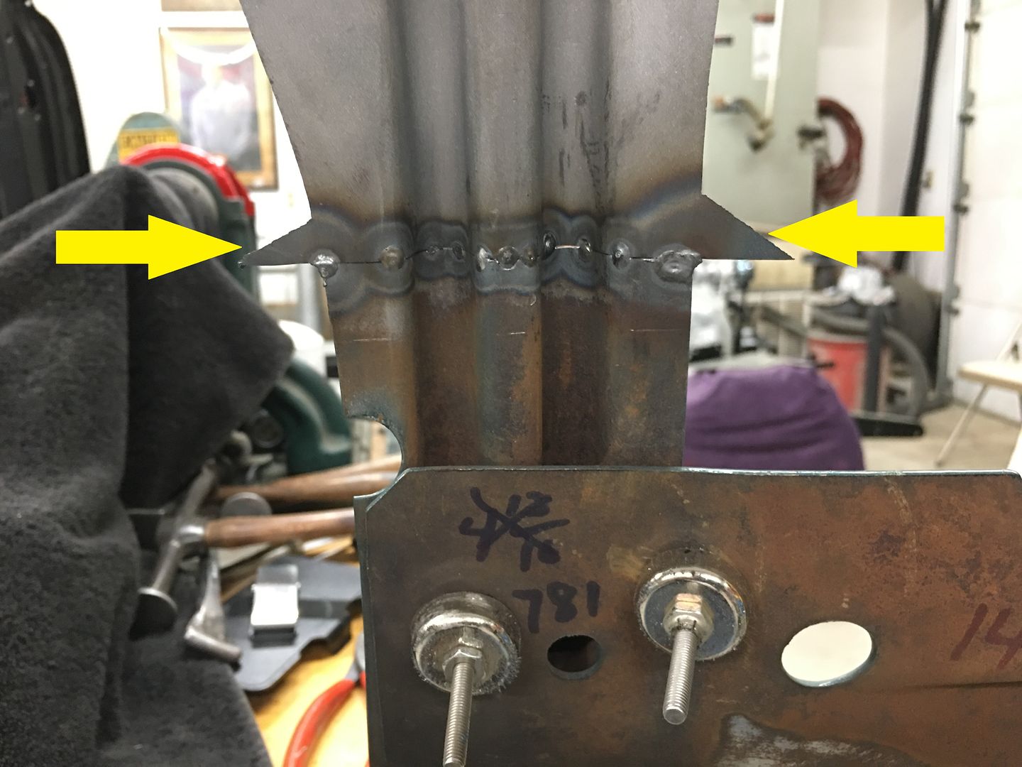
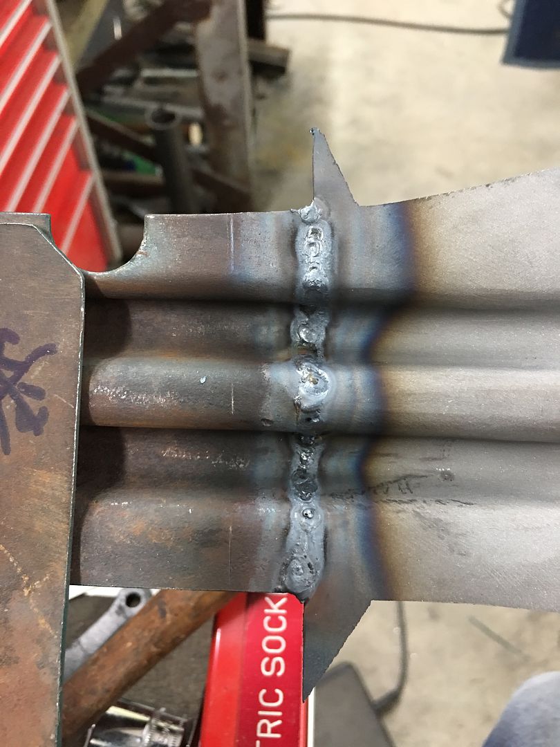
The entire seam is TIG welded and then our batwings are trimmed using offset snips, then welds dressed..
One down......
Working outward, the panel surfaces are aligned and tacked as we go. Note the "batwings" left on the outside of the new brace end (yellow arrows). This will act as a heat sink when we make the outer tacks. Had these been trimmed to match prior to welding, the edge will have a tendency to burn back from the heat.
The entire seam is TIG welded and then our batwings are trimmed using offset snips, then welds dressed..
One down......
Thread Starter
|
Tuned
Joined: Aug 2007
Posts: 457
Likes: 115
From: Maryland
Starting on the other end of the hood brace, this one not as rotted as the other but has issues just the same. One of those "while we're here" things....
The ribs are trimmed and ends rounded.. A piece of flat 16 gauge is trimmed to fit..
tacked together....
….then the photographer went on strike until we got to this...
We'll get this trimmed and installed tomorrow..
The ribs are trimmed and ends rounded.. A piece of flat 16 gauge is trimmed to fit..
tacked together....
….then the photographer went on strike until we got to this...
We'll get this trimmed and installed tomorrow..
Thread Starter
|
Tuned
Joined: Aug 2007
Posts: 457
Likes: 115
From: Maryland
More progress on the hood, here is the other end of the hood brace.
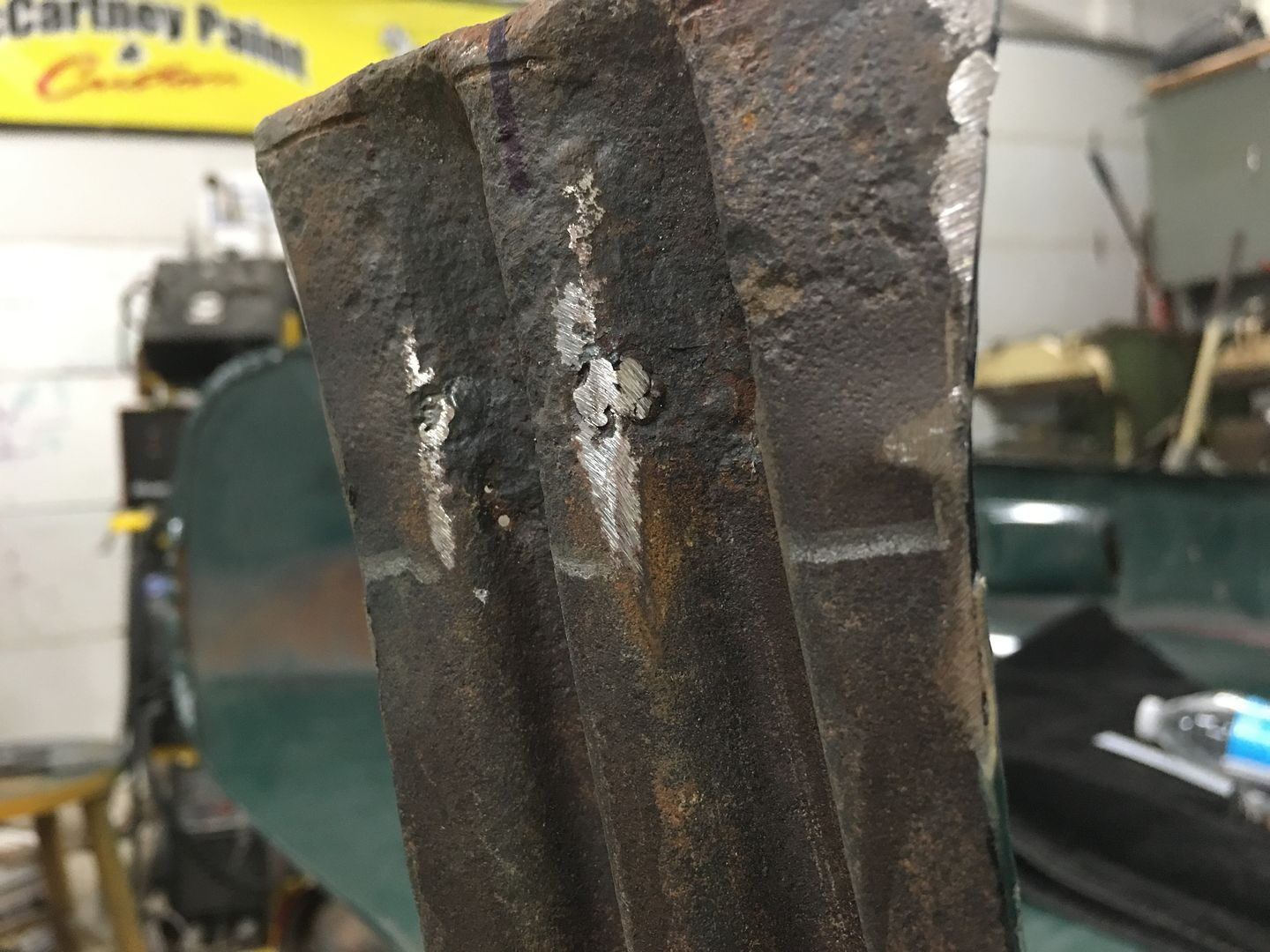
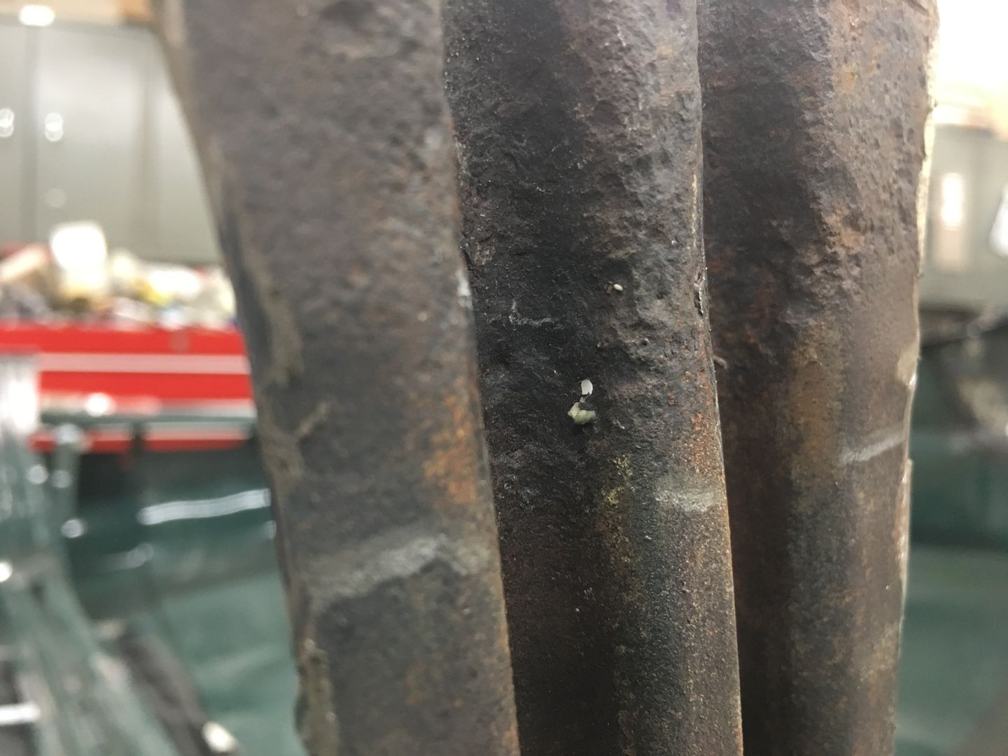
Looking at the back side, you can see where a few holes were welded closed the last time it was painted, and the severe pitting and new holes that we have. A testament to the fact that what shows is always the tip of the iceberg. Although better than the passenger side, this is definitely one of those "while we are here" things. Do it right, do it once. (grinder marks were mine)
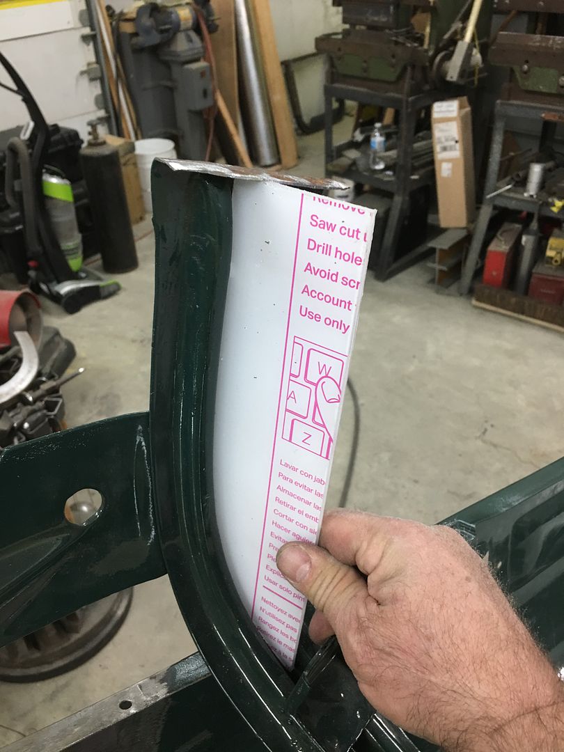
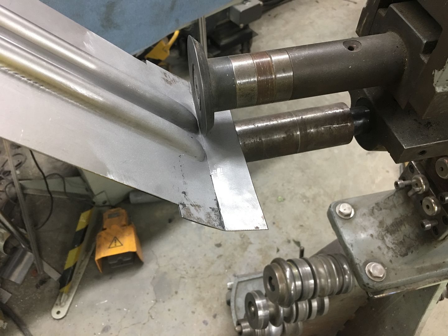
With our new replacement all one piece, the next step is to bend the flange that spot welds to the hood skin. A tipping wheel in the Fasti-werks bead roller makes quick work of it. The bend line was transposed from the original and an initial pass under the tipping die marks the crease line a bit better, Then successive passes are made, lifting slightly with each pass. This is done until the beads interfere with the tipping die.
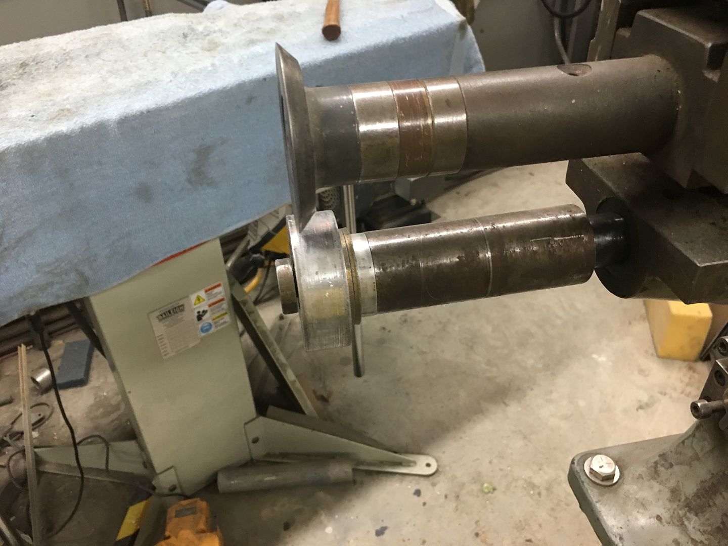
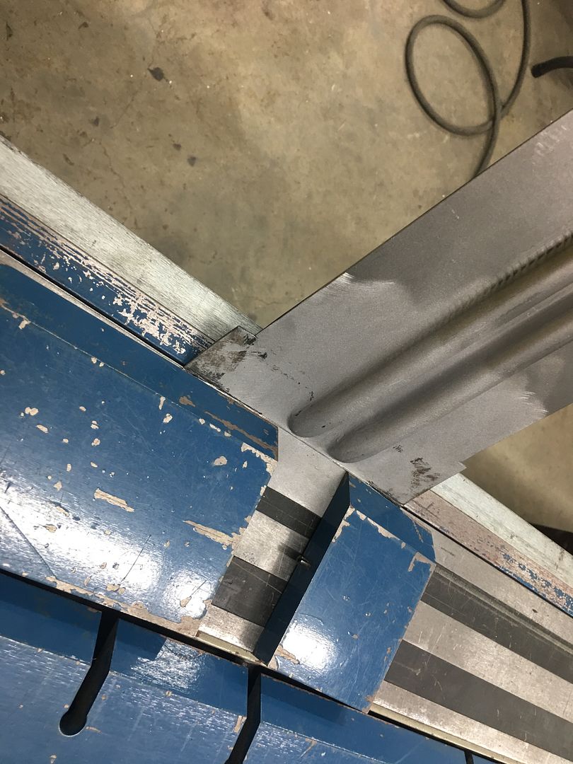
Then the partial bent flange is clamped in the magnetic brake for the remainder of the fold. This brake allows us to use a die on either side of the bead details, where a full die may inadvertently push in on the beads.
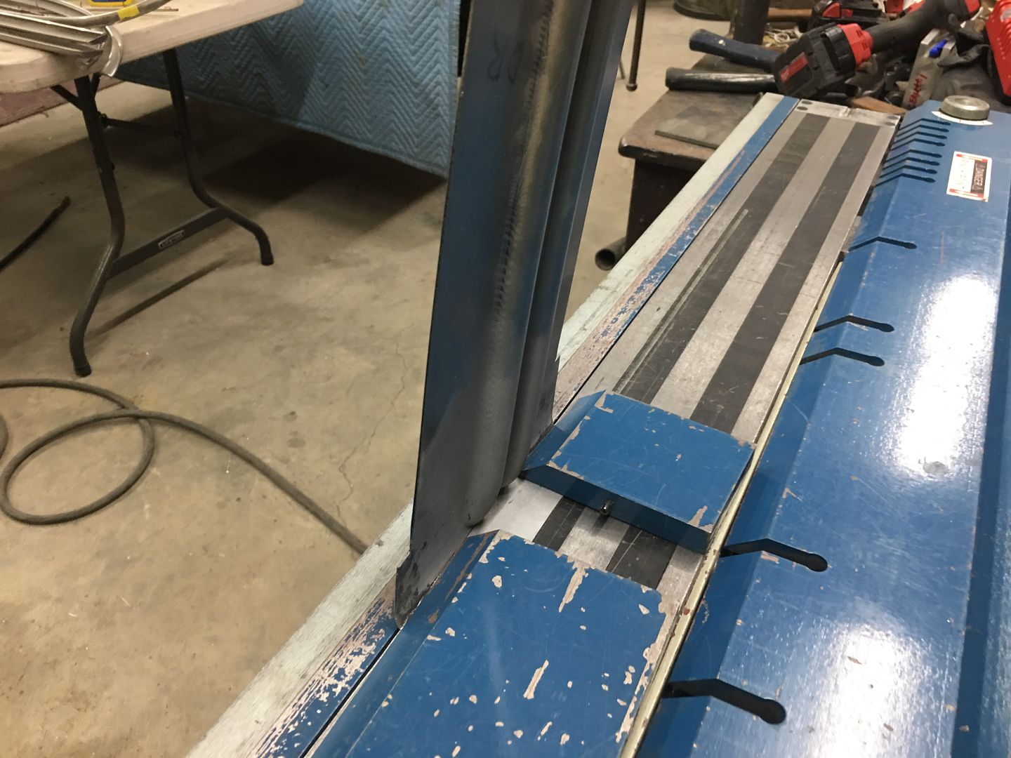
End gets cut to length and marked for initial trimming
Looks like we may have enough bead stock left for another couple of ends.
That's where we left off yesterday, we'll see about welding the new end on today..
.
Looking at the back side, you can see where a few holes were welded closed the last time it was painted, and the severe pitting and new holes that we have. A testament to the fact that what shows is always the tip of the iceberg. Although better than the passenger side, this is definitely one of those "while we are here" things. Do it right, do it once. (grinder marks were mine)
With our new replacement all one piece, the next step is to bend the flange that spot welds to the hood skin. A tipping wheel in the Fasti-werks bead roller makes quick work of it. The bend line was transposed from the original and an initial pass under the tipping die marks the crease line a bit better, Then successive passes are made, lifting slightly with each pass. This is done until the beads interfere with the tipping die.
Then the partial bent flange is clamped in the magnetic brake for the remainder of the fold. This brake allows us to use a die on either side of the bead details, where a full die may inadvertently push in on the beads.
End gets cut to length and marked for initial trimming
Looks like we may have enough bead stock left for another couple of ends.
That's where we left off yesterday, we'll see about welding the new end on today..
.
Trending Topics
Thread Starter
|
Tuned
Joined: Aug 2007
Posts: 457
Likes: 115
From: Maryland
Our last end for the hood brace. Off with the old.....
Then it gets trimmed to our scribe line and the end media blasted in prep for welding. Our new end is test fit and trimmed until we get the right distance to our reference marks. The "batwings" give us a heat sink at the edge for less chance of burning back the edge at the weld.
The center rib is aligned both on the sides and the face, and tacked in position using the TIG.
The pieces are aligned as we work outward, tacking as we go. A "corking tool" is used as a dolly where any bumping may be needed for alignment.
Tacked...
Welded....
Welds cleaned up and end angles compared..
Now we can get back to straightening sheet metal..
FTE Stories
Ford Trucks for Ford Truck Enthusiasts

AEV FXL Super Duty - the Super Duty Raptor Ford Doesn't Make
Brett Foote
Lobo Vs Lobo: Proof the F-150 Lobo Should Be Even Lower!
Michael S. Palmer
Ford's 2001 Explorer Sportsman Concept Looks For a New Home
Verdad Gallardo
10 Best Ford Truck Engines We Miss the Most!
Joe Kucinski
2026 Shelby F-150 Off-Road: Better Than a Raptor R?
Brett Foote
2027 Super Duty Carhartt Package First Look: 12 Things You NEED to Know!
Michael S. Palmer
10 Most Surprising 2026 Ford Truck Features!
Joe Kucinski
Top 10 Ford Trucks Coming to Mecum Indy 2026
Brett Foote
5 Best / 5 Worst Ford Truck Wheels of All Time
Joe KucinskiThread Starter
|
Tuned
Joined: Aug 2007
Posts: 457
Likes: 115
From: Maryland
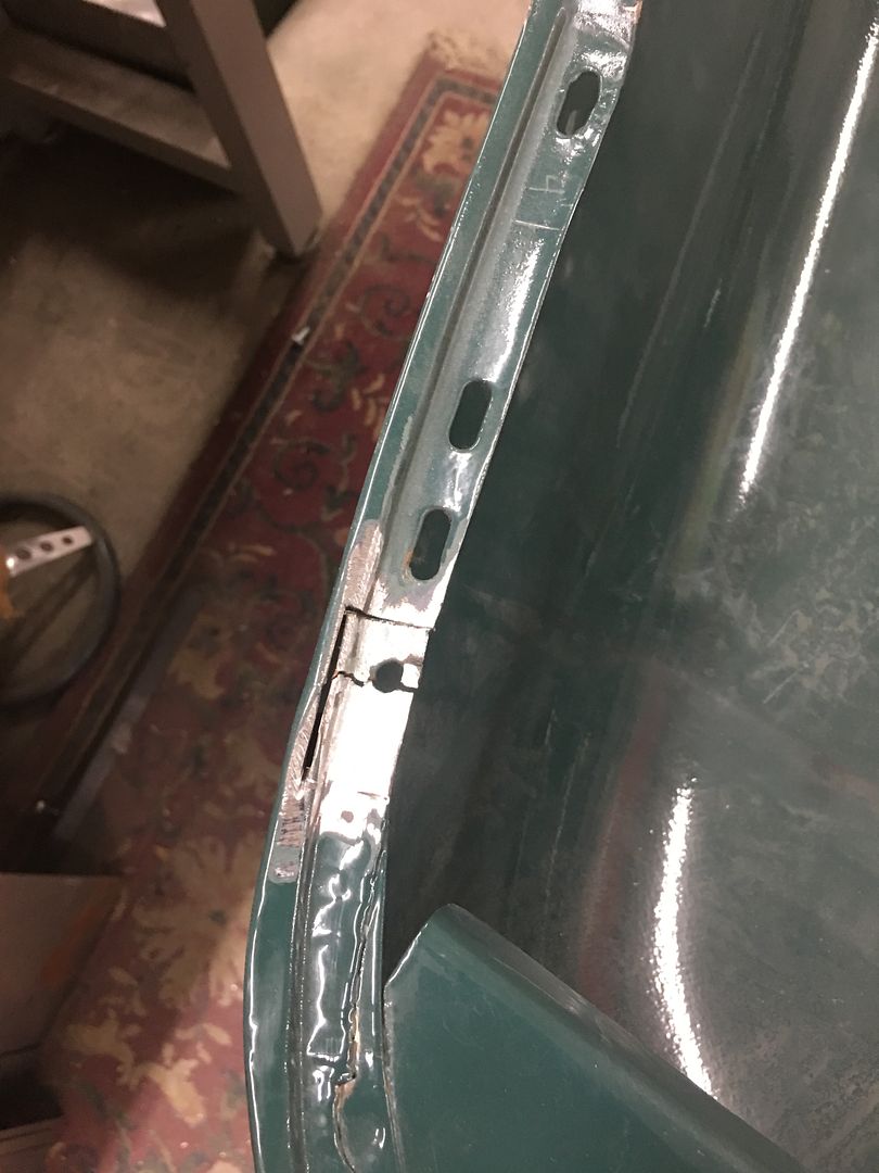
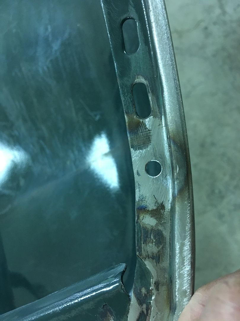
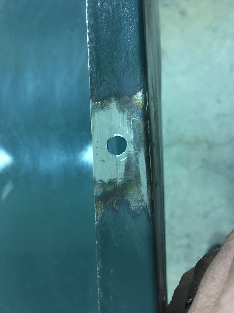
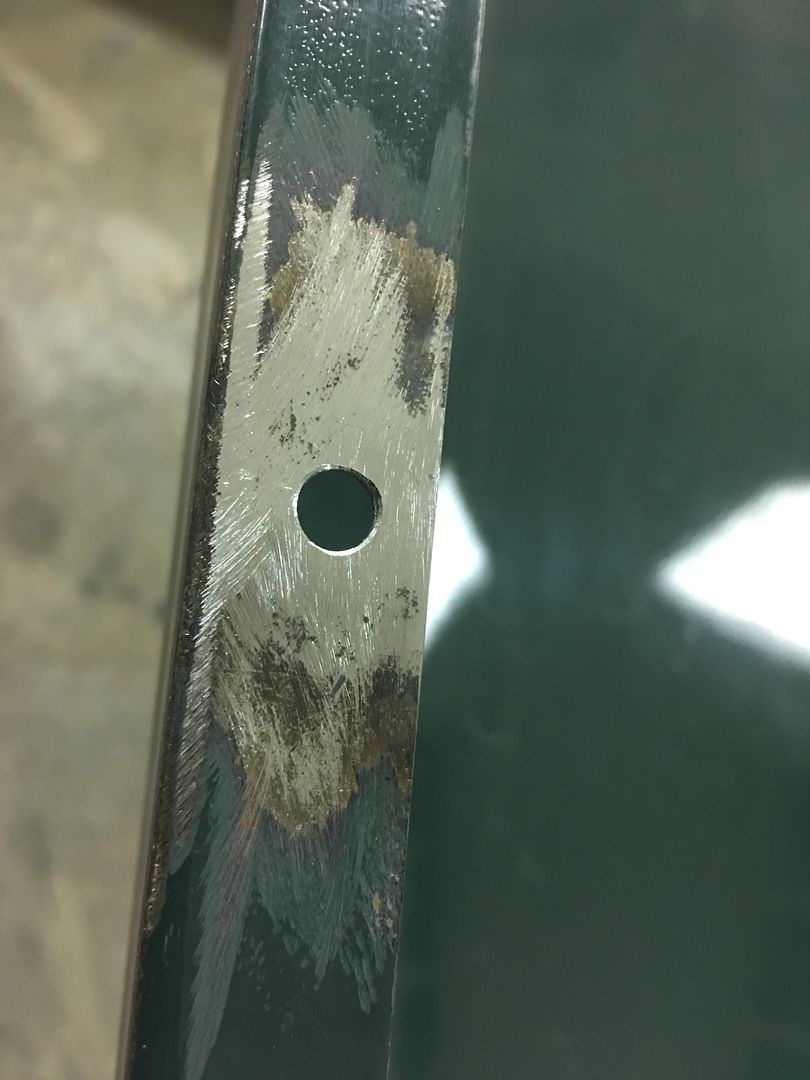
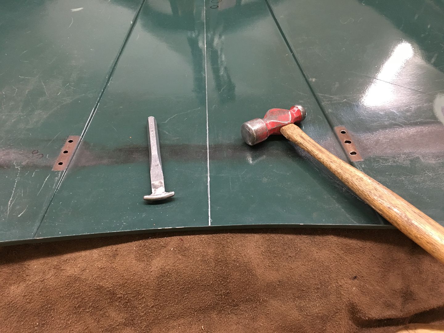
We have a few more spots to fix from cracking and fatigue, namely the holes on the underside for the rubber hood bumpers. We've already repaired three, and from the looks of it, need to take care of the remaining three..
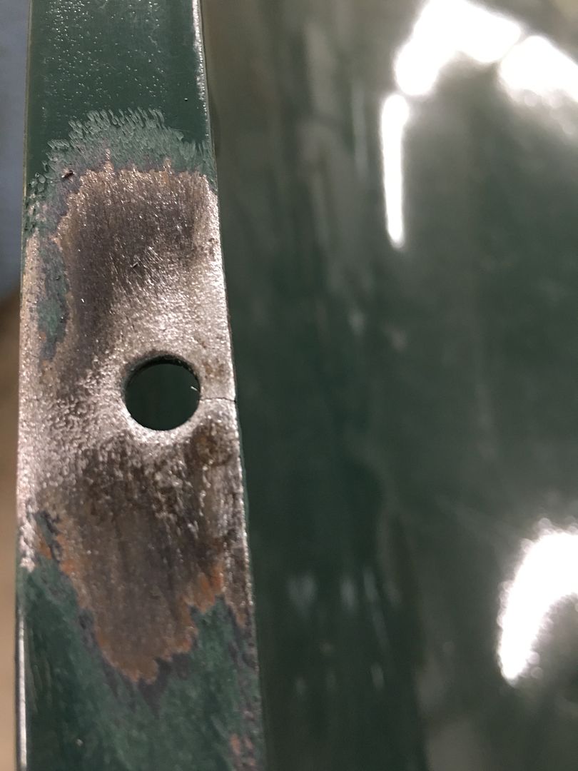
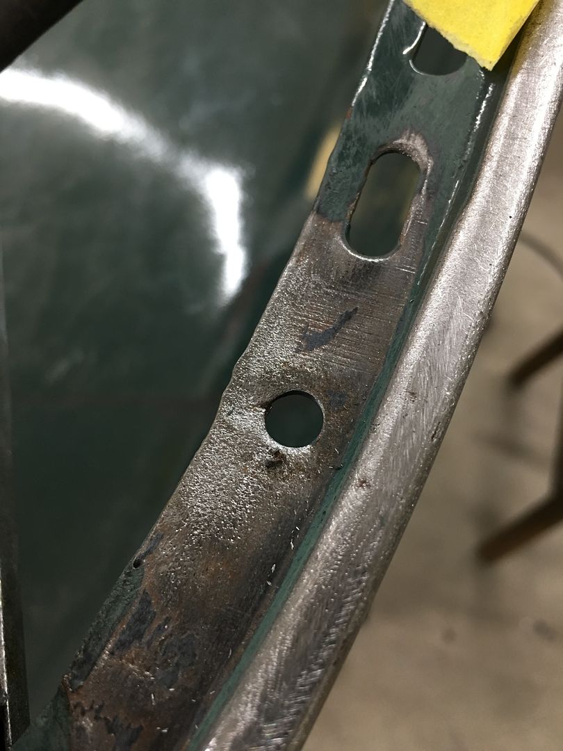
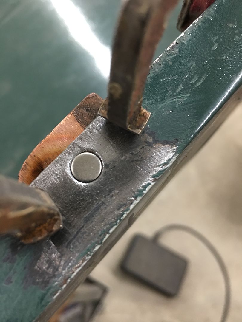
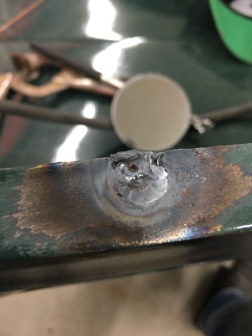
18 Gauge x 1/4" plugs were TIG welded in to fill the existing holes, and a copper backer gives us a bit of a heat sink so the cracks/fatigued areas don't blow a big hole on us..
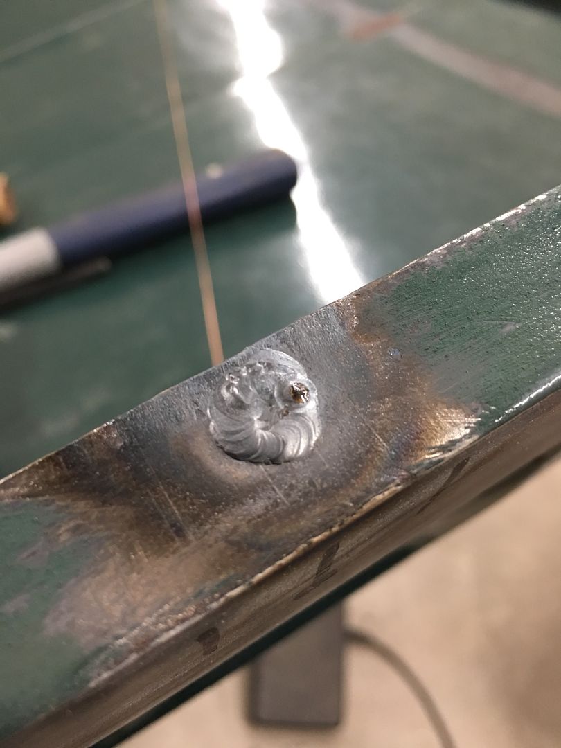
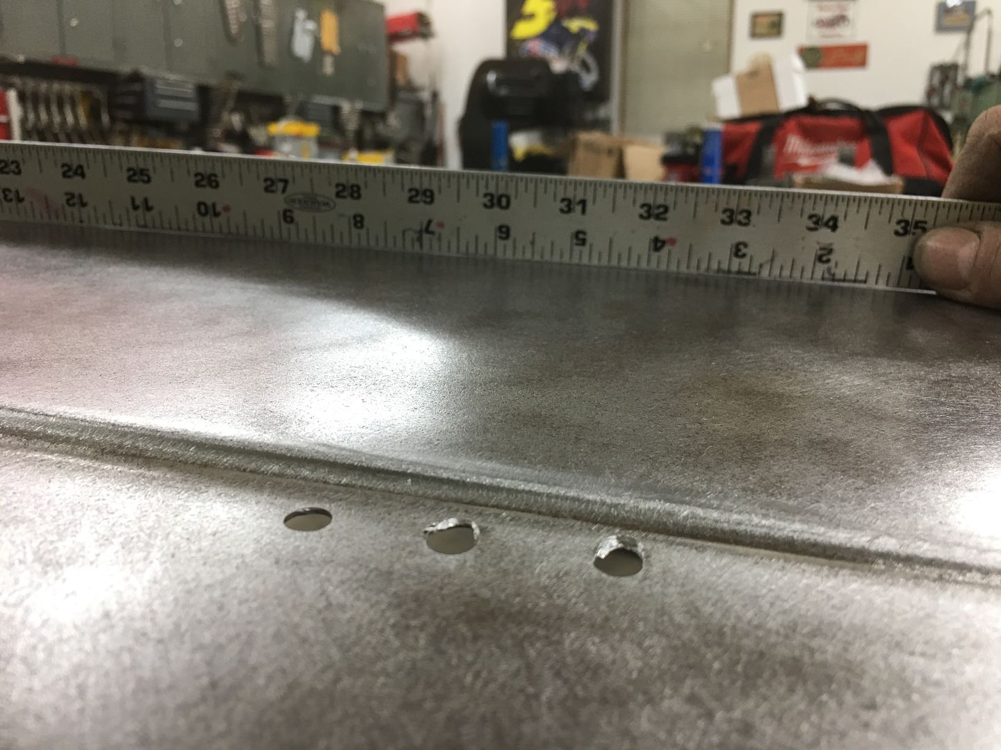
Welds were dressed on both sides of the sheet metal, and new holes drilled slightly in farther from the edge to help slow down the reappearance of cracks.
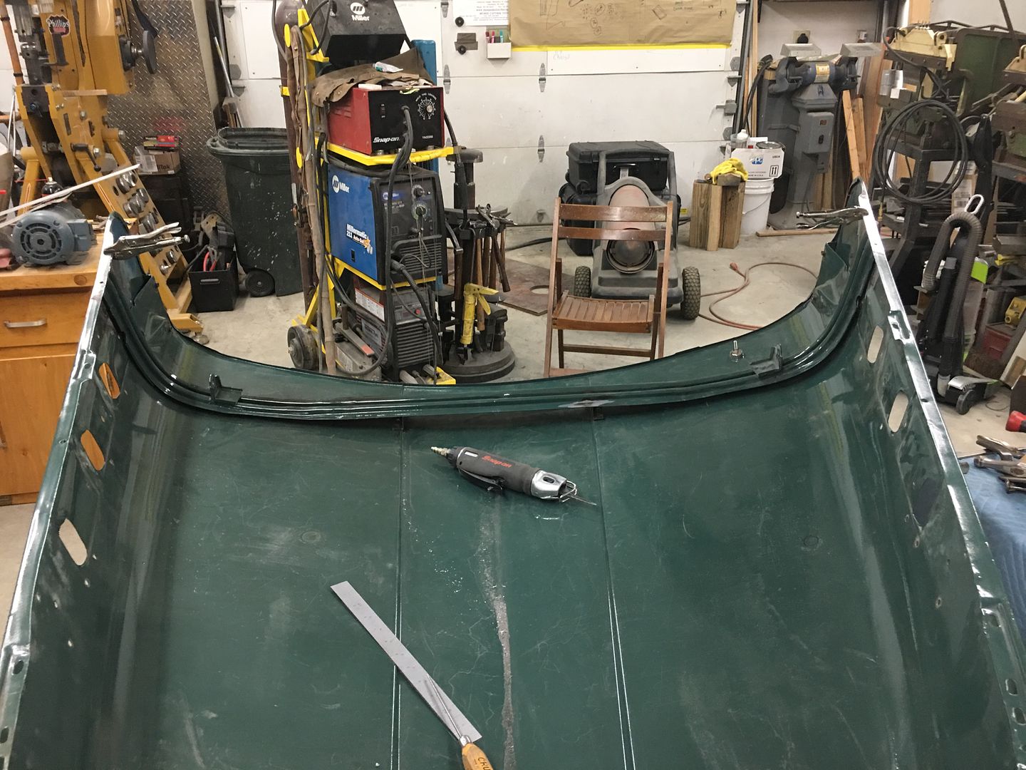
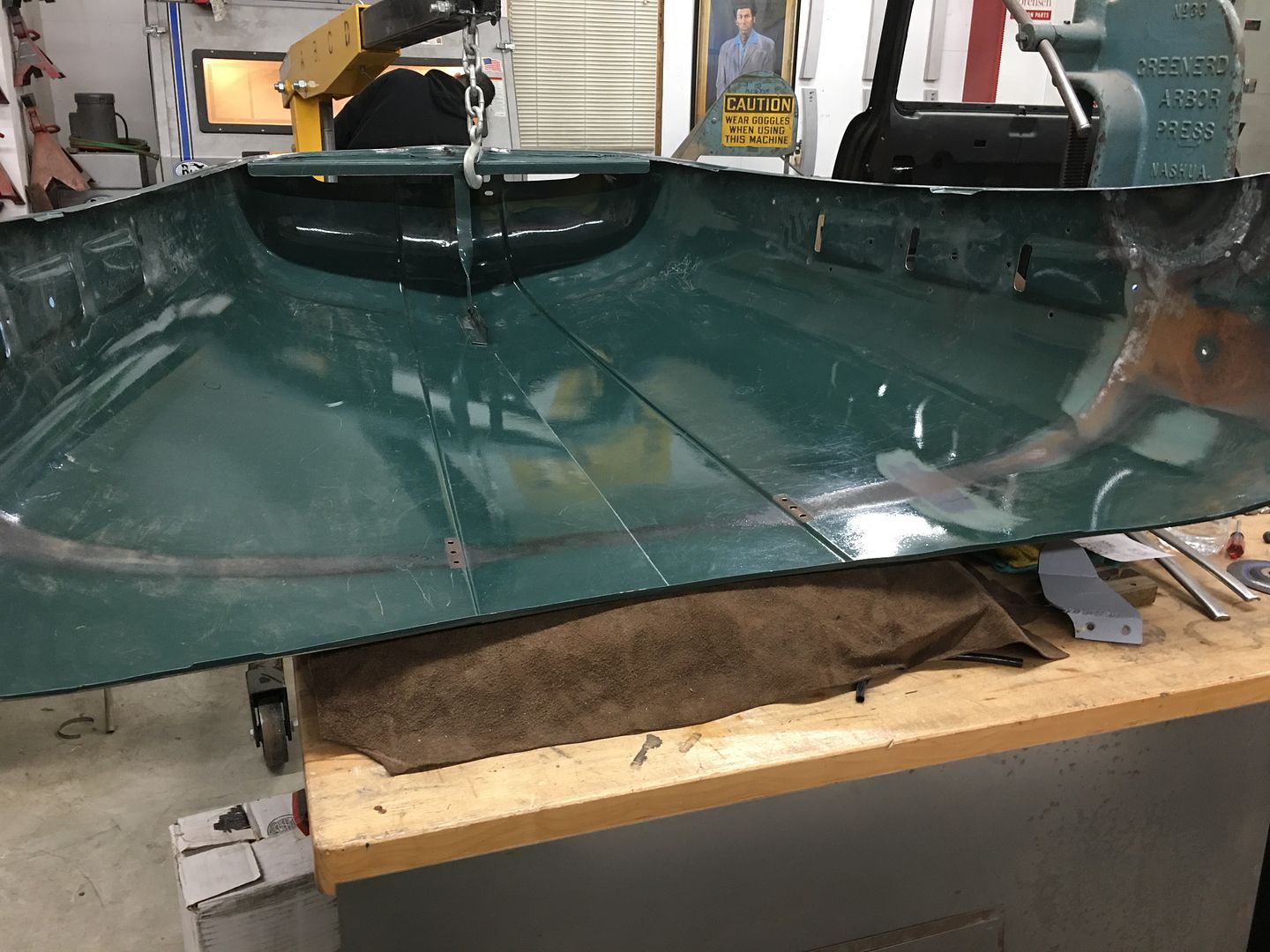
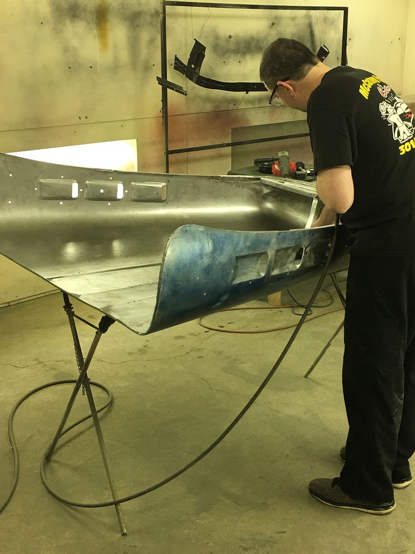
Next, I'm sure everyone has seen how these hoods can oil can, show low spots, and try to flop around while driving down the road. Part of that is abuse over the years, fatigue, etc. Any low spots invariably result in a loss of support of the hood and will show oil cans or loose areas.
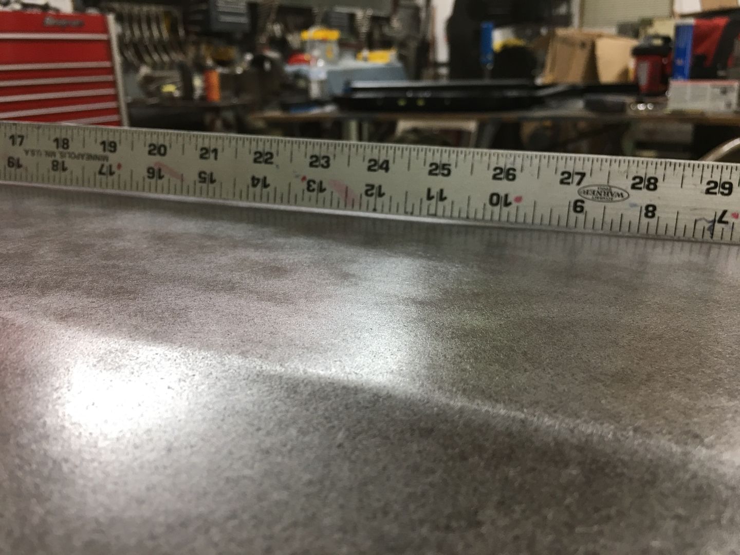
A good tool to check the crown of the hood is a long straight edge in the form of a 36" rule. If you don't have one, most hardware stores sell aluminum flat bar for a few dollars that will make a good profile template. For this style hood, lows are bad, straight is better, and a slight crown in the center crease along the entire length of the "flat" area of the hood is optimal.. This gives the support to help eliminate those oil cans and floppy hoods.
When we started there was an obvious area about 12" forward of the rear edge, dead center, that appears low, and was easily pushed downward. In order to better define the center crease and provide the support needed, we will use a sand bag (a rather large one) and lightly hammer from the bottom side into said bag with a purpose built "punch".
In order to keep the back portion of the hood down against the bag for support, we used our latest "metalshaping" tool to hold the front of the hood up, an engine hoist..
A reference mark is used on the inside, measured and centered...
The crease was checked for low spots prior, and the bottom marked. The "punch" is dragged along the centerline and tapped as you go. Flip the hood over, check crown, remark as needed, repeat. We got to a good straight/slight crown and the oil can disappeared. Pushing along the entire center crease was a nice tight support now..
So if you are having issue with your hood, I would suggest first checking your center crease.
18 Gauge x 1/4" plugs were TIG welded in to fill the existing holes, and a copper backer gives us a bit of a heat sink so the cracks/fatigued areas don't blow a big hole on us..
Welds were dressed on both sides of the sheet metal, and new holes drilled slightly in farther from the edge to help slow down the reappearance of cracks.
Next, I'm sure everyone has seen how these hoods can oil can, show low spots, and try to flop around while driving down the road. Part of that is abuse over the years, fatigue, etc. Any low spots invariably result in a loss of support of the hood and will show oil cans or loose areas.
A good tool to check the crown of the hood is a long straight edge in the form of a 36" rule. If you don't have one, most hardware stores sell aluminum flat bar for a few dollars that will make a good profile template. For this style hood, lows are bad, straight is better, and a slight crown in the center crease along the entire length of the "flat" area of the hood is optimal.. This gives the support to help eliminate those oil cans and floppy hoods.
When we started there was an obvious area about 12" forward of the rear edge, dead center, that appears low, and was easily pushed downward. In order to better define the center crease and provide the support needed, we will use a sand bag (a rather large one) and lightly hammer from the bottom side into said bag with a purpose built "punch".
In order to keep the back portion of the hood down against the bag for support, we used our latest "metalshaping" tool to hold the front of the hood up, an engine hoist..
A reference mark is used on the inside, measured and centered...
The crease was checked for low spots prior, and the bottom marked. The "punch" is dragged along the centerline and tapped as you go. Flip the hood over, check crown, remark as needed, repeat. We got to a good straight/slight crown and the oil can disappeared. Pushing along the entire center crease was a nice tight support now..
So if you are having issue with your hood, I would suggest first checking your center crease.
Thread Starter
|
Tuned
Joined: Aug 2007
Posts: 457
Likes: 115
From: Maryland
The 51 F7 hood is closer to reuniting with the brace with the newly repaired ends.. Epoxy primer will be under the brace this time around to help prevent the new side patches from rusting again..
.JPG)
.JPG)
.JPG)
Thread Starter
|
Tuned
Joined: Aug 2007
Posts: 457
Likes: 115
From: Maryland
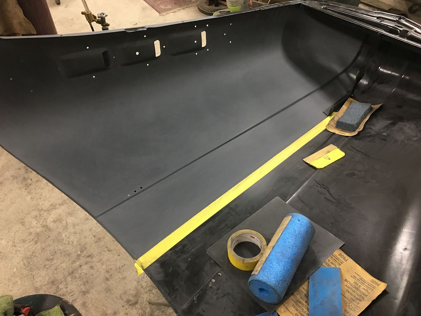
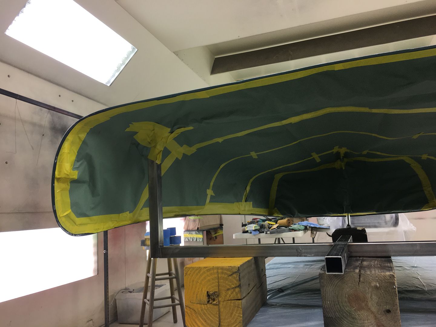
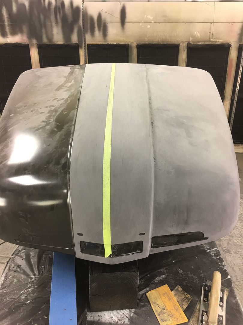
Playing catch-up here, the inside of the crease was blocked using tape to keep the center line sharp, then brace welded in place and some epoxy touch ups done..
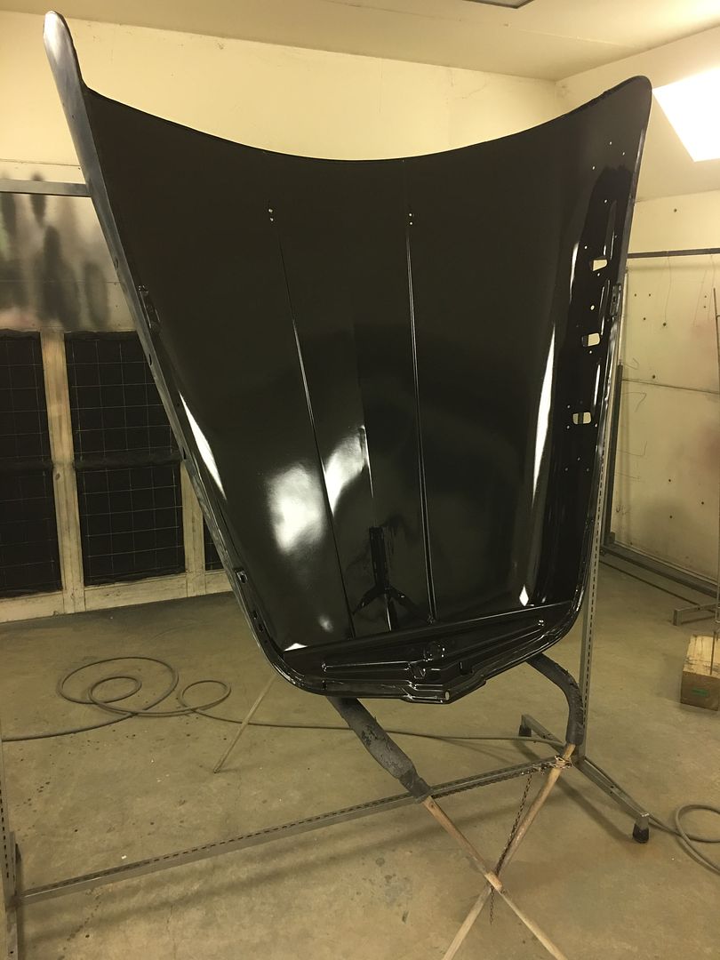
With the touch ups blocked, we're ready for some Epoxy/sealer, some PPG ESSS base, and my first time spraying SPI Universal... WooHoo! love this clear!!
These Ford truck hoods can be a pain to get good paint coverage inside the nose.. So a couple pieces of TIG wire from our rack to the hood brackets hold it up in the air so we can get into the nose with the spray gun..
Thread Starter
|
Tuned
Joined: Aug 2007
Posts: 457
Likes: 115
From: Maryland
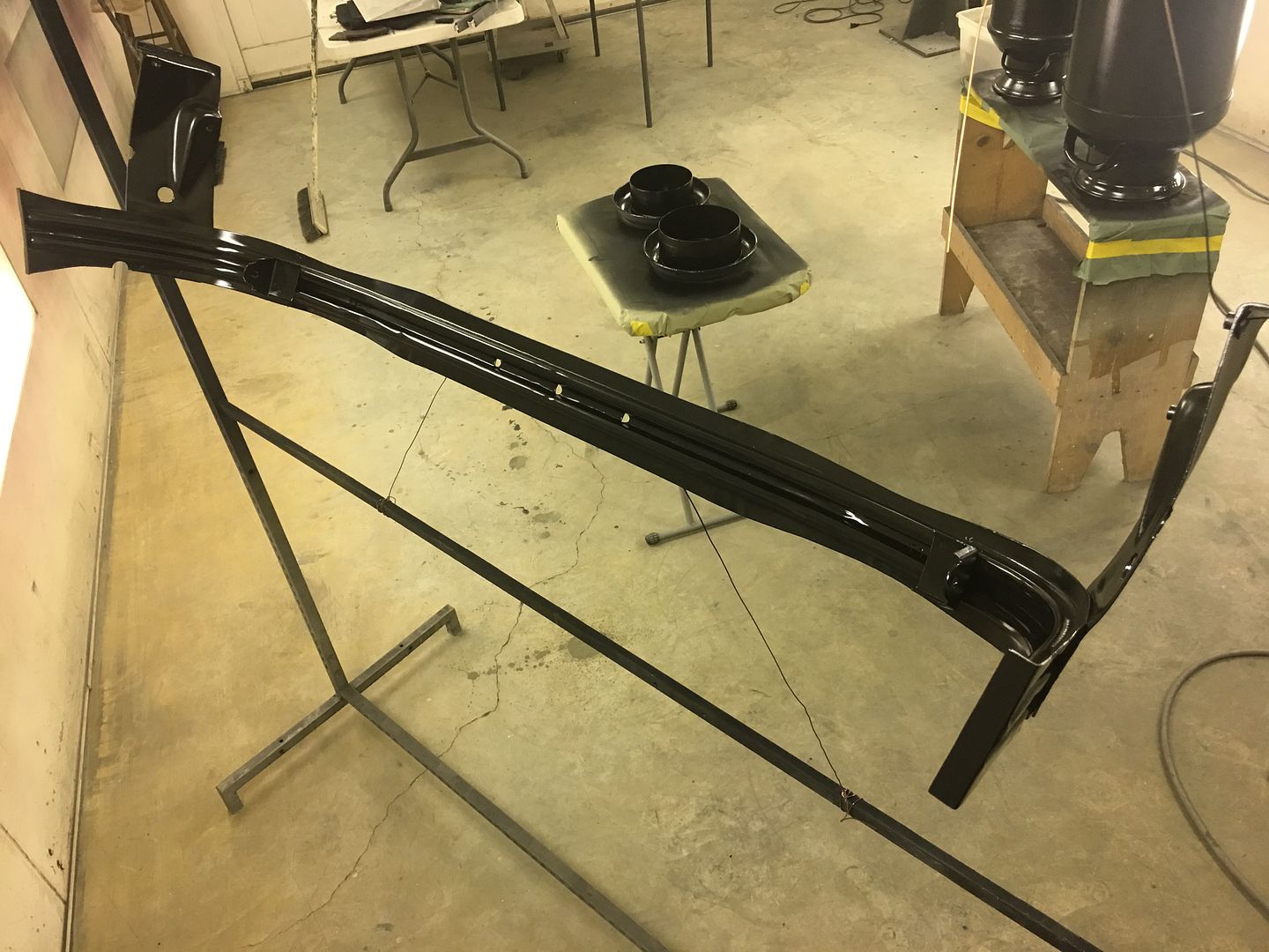
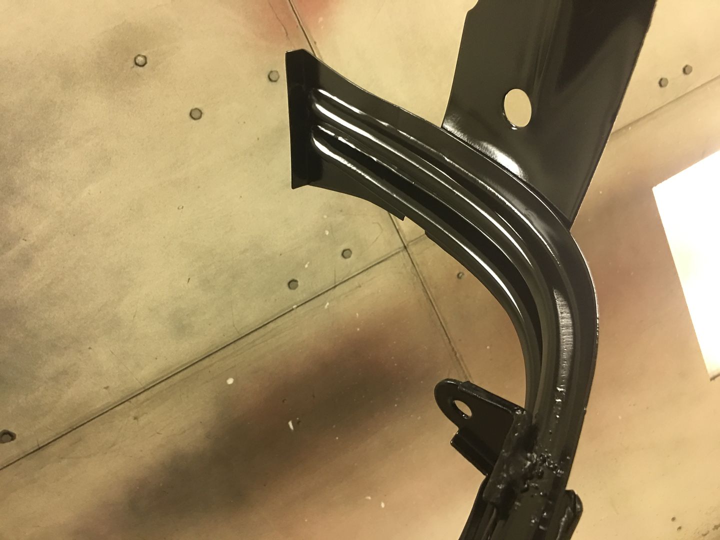
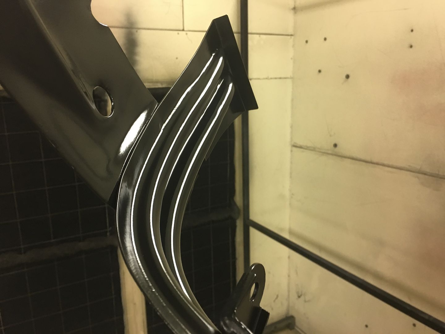
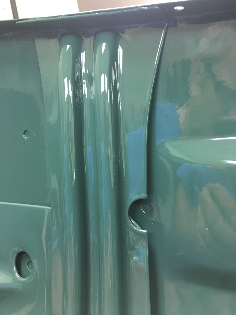
Thought I'd do a progression of pictures to show the carnage we started with on the hood brace to where it was painted this past weekend....

Note the wings left adjacent to the weld to act as heat sinks and prevent the edge from burning back...

No Body filler, just epoxy primer, basecoat, and clearcoat. Looks almost factory!!
Note the wings left adjacent to the weld to act as heat sinks and prevent the edge from burning back...
No Body filler, just epoxy primer, basecoat, and clearcoat. Looks almost factory!!
Thread Starter
|
Tuned
Joined: Aug 2007
Posts: 457
Likes: 115
From: Maryland
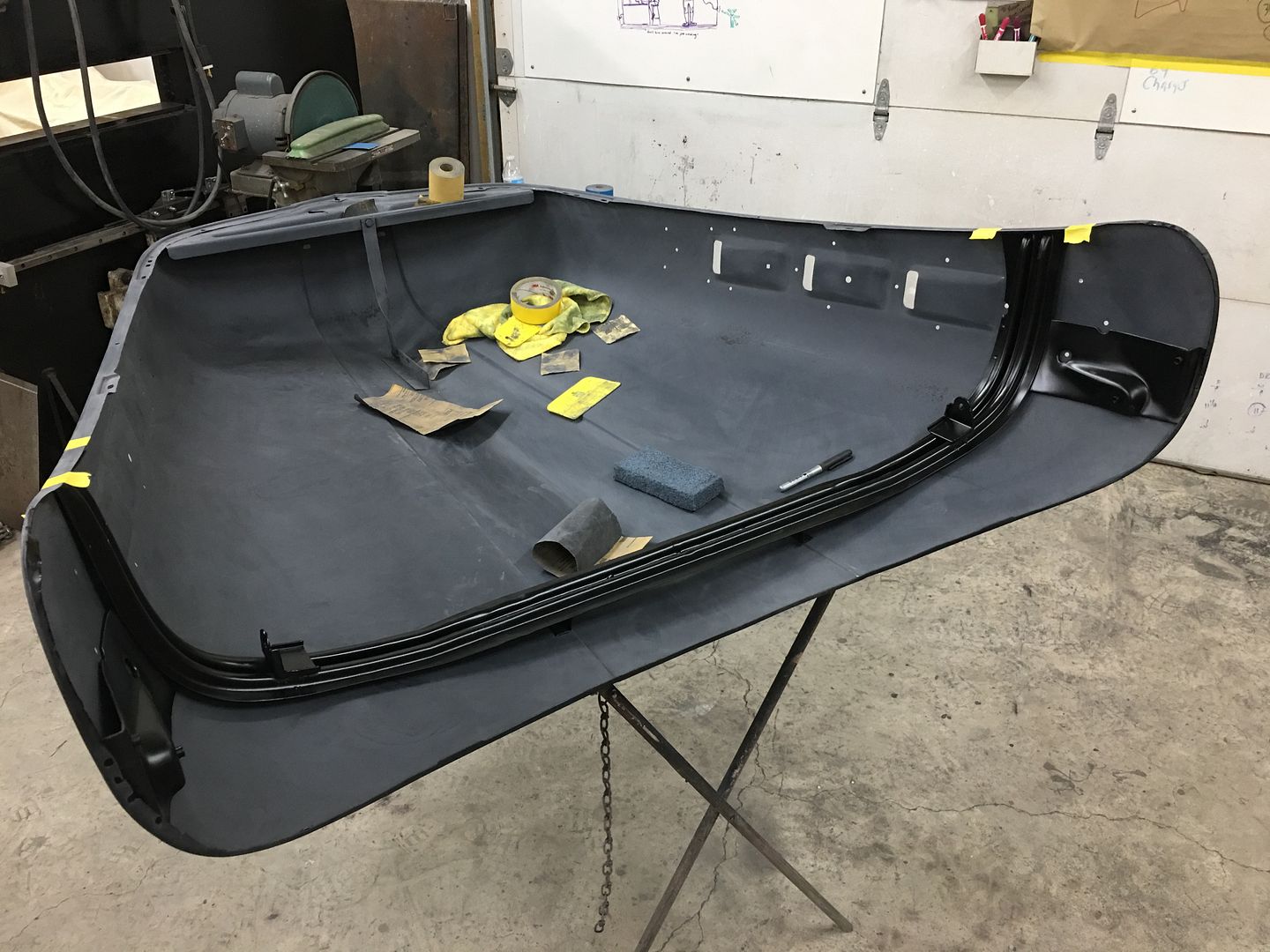
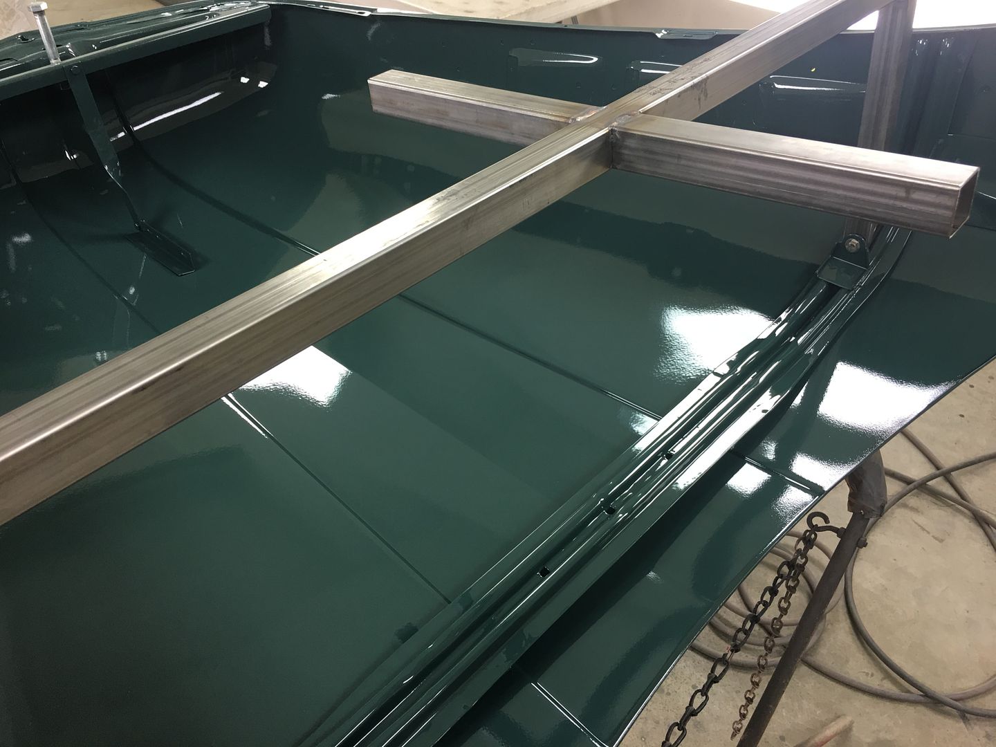
So every time we place the hood on my folding stand, the hood skin deflects upward at those pressure points (corners). Which means that won't work for blocking out the hood. So lets' use the same supports that the hood uses and make a blocking "stand".
Large 5/8" bolt through the hood latch hole for supporting the nose...
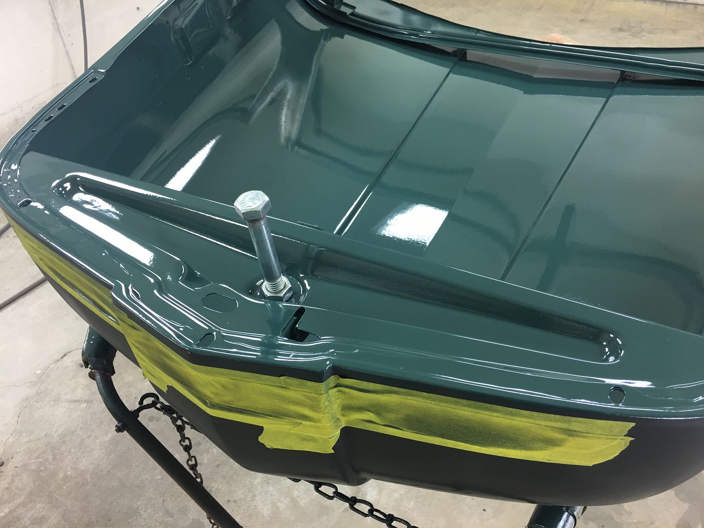
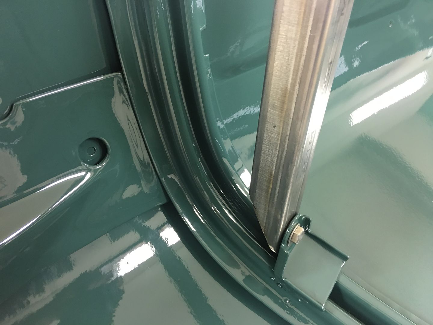
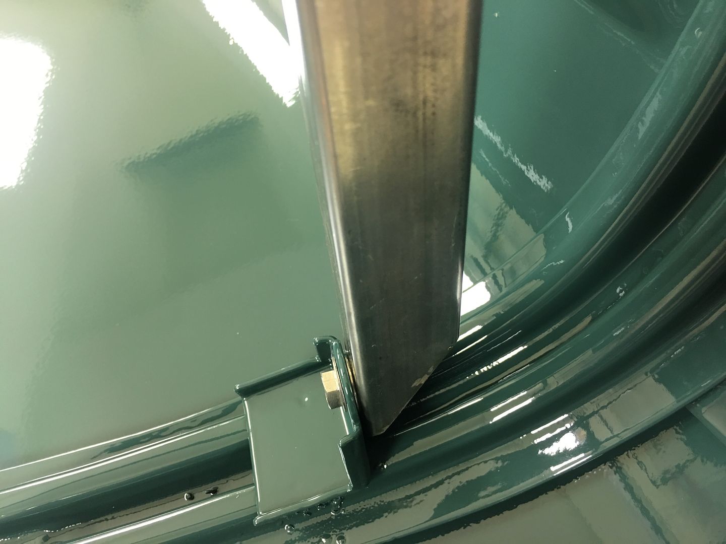
And going through our scrap inventory, here's some tubing we used for the back end, bolted into the hinge support. The extra "feet" help to stabilize it so the sanding effort won't try and flop it over...
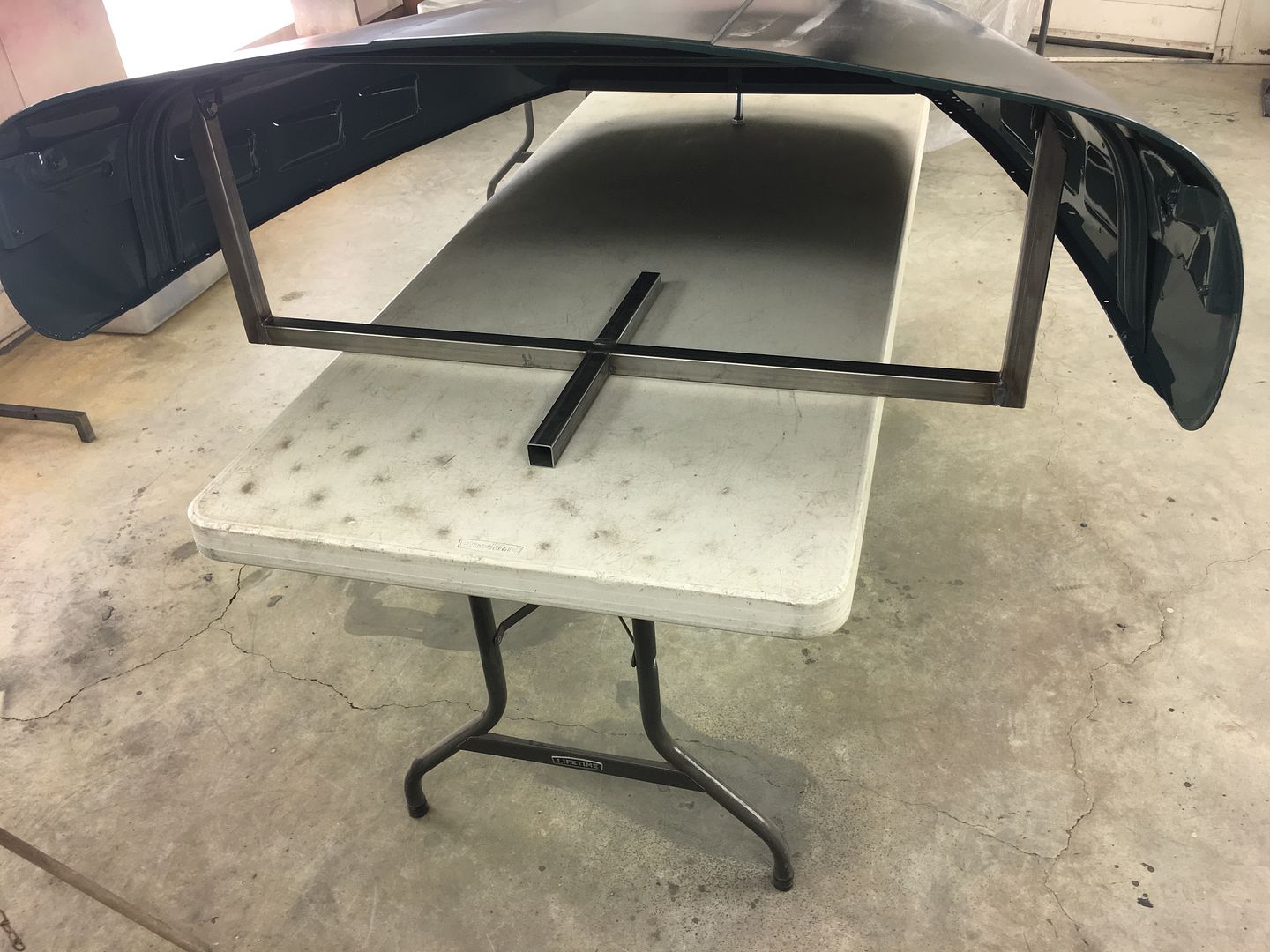
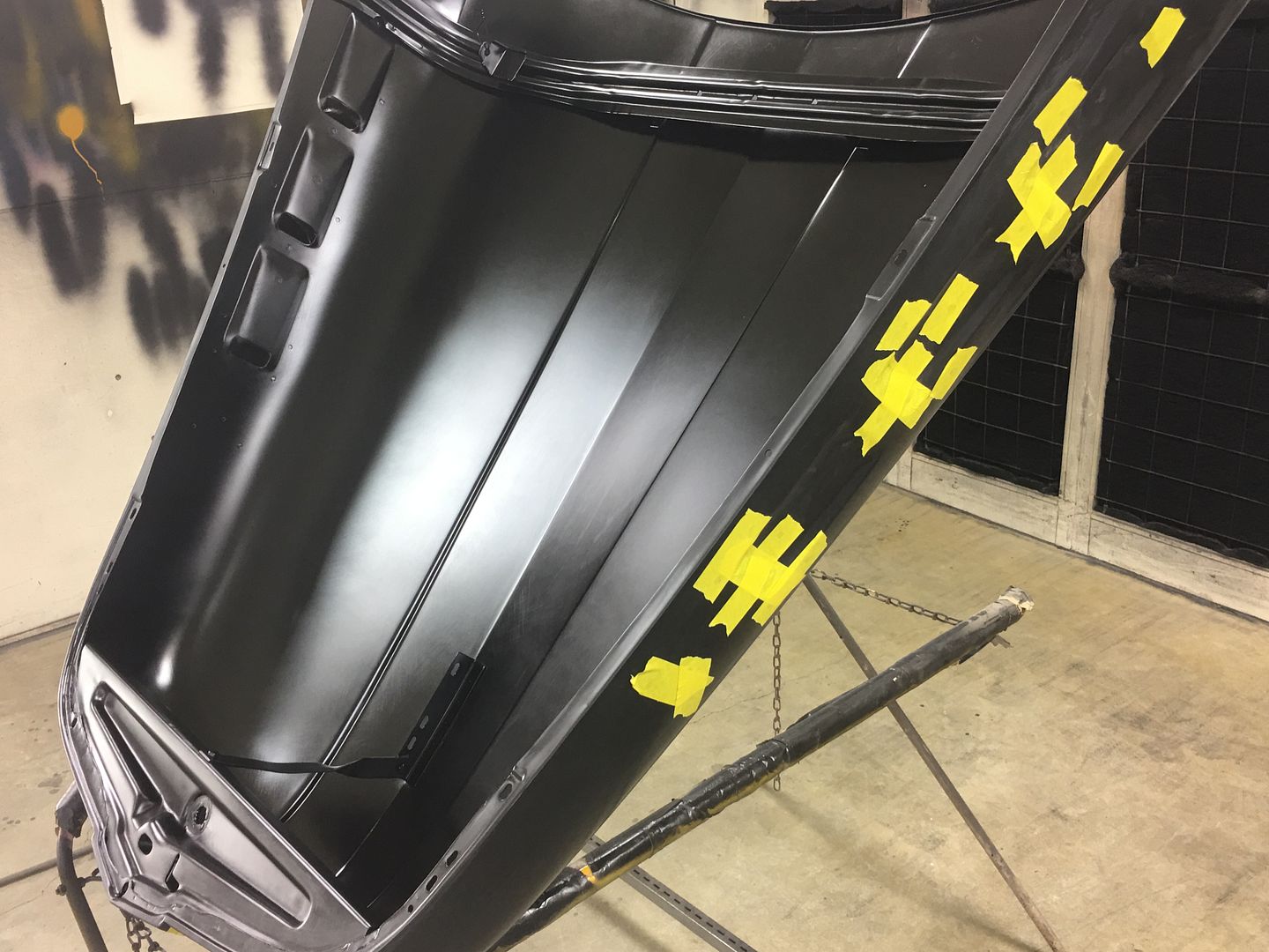
With that done, all our open holes are taped over and the entire bottom side masked off to protect the inside finish..

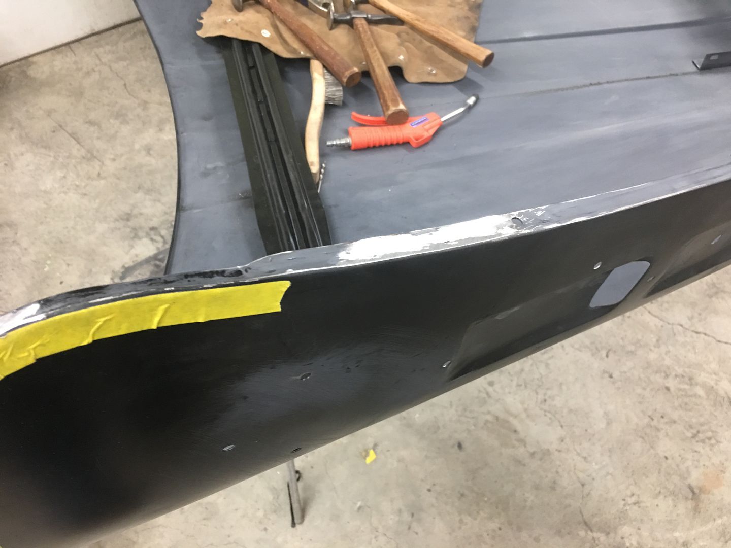
A bit of Evercoat 416 to address some lows, and 3 coats of SPI epoxy for the next round of blocking on the outside.
Blocking...
Some booth clean up and fresh masking on the table, hood pre-cleaned and tacked.....
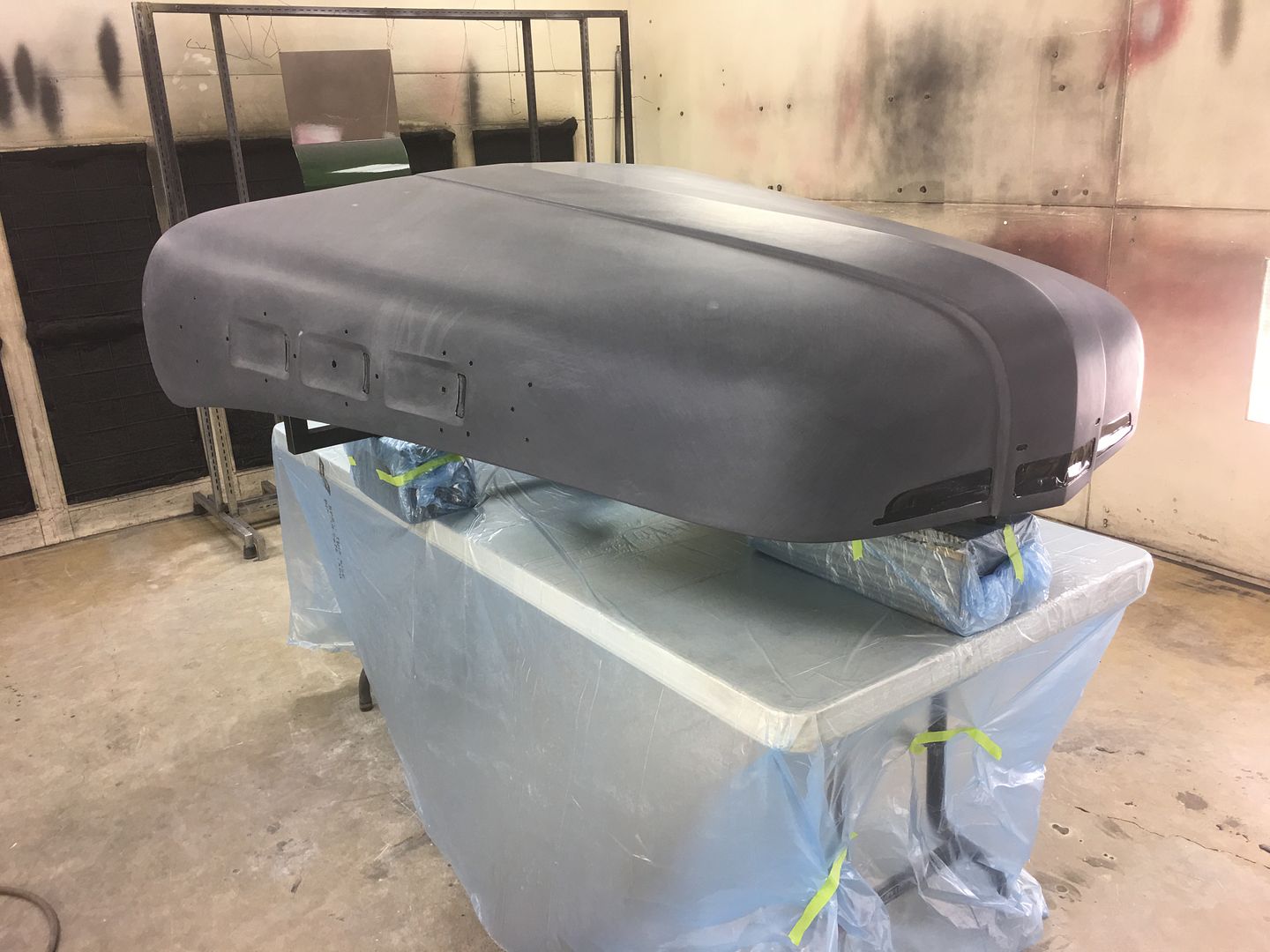
Sealed with SPI Epoxy thinned about 10%
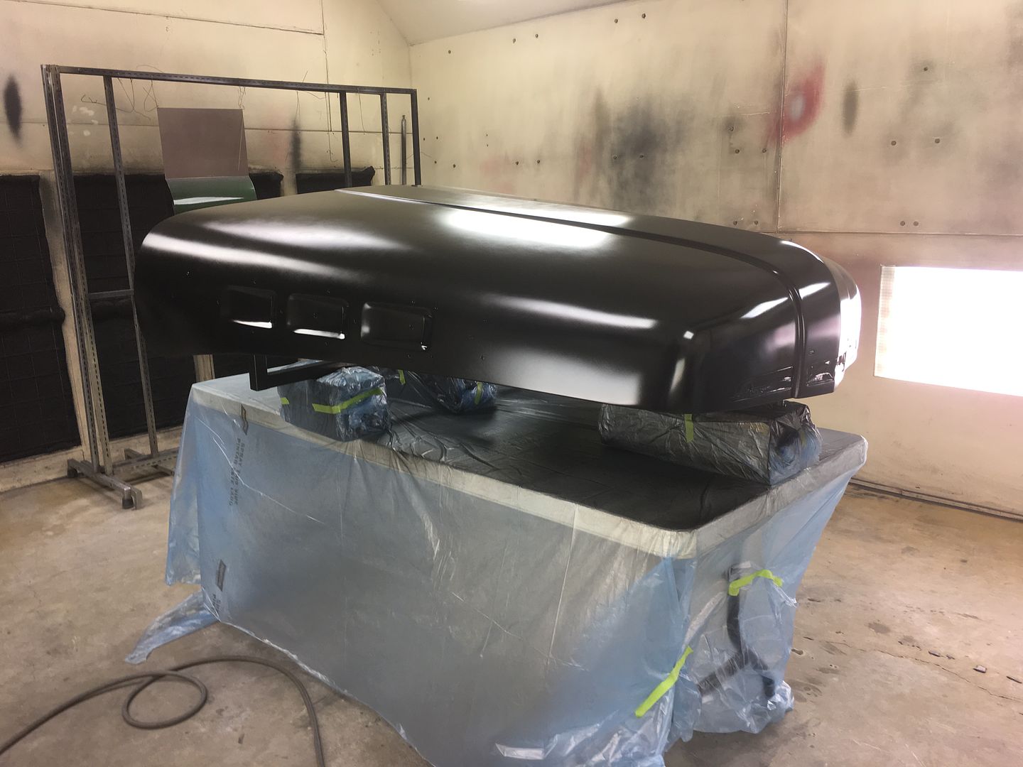
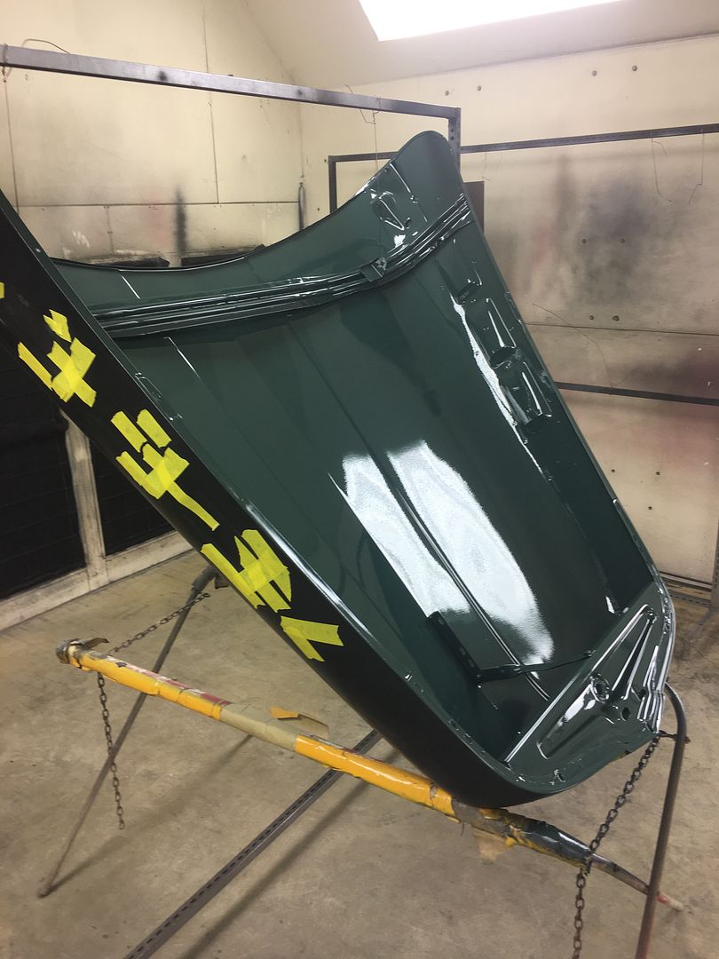
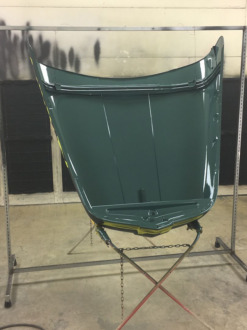
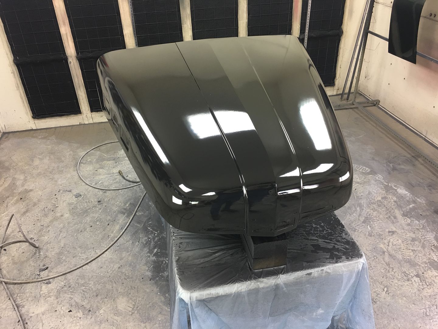
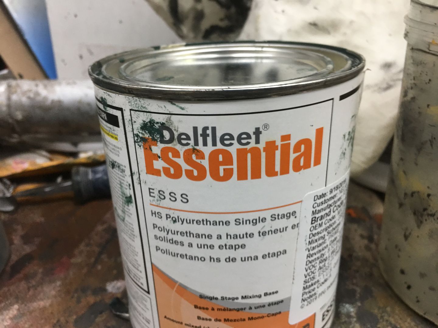
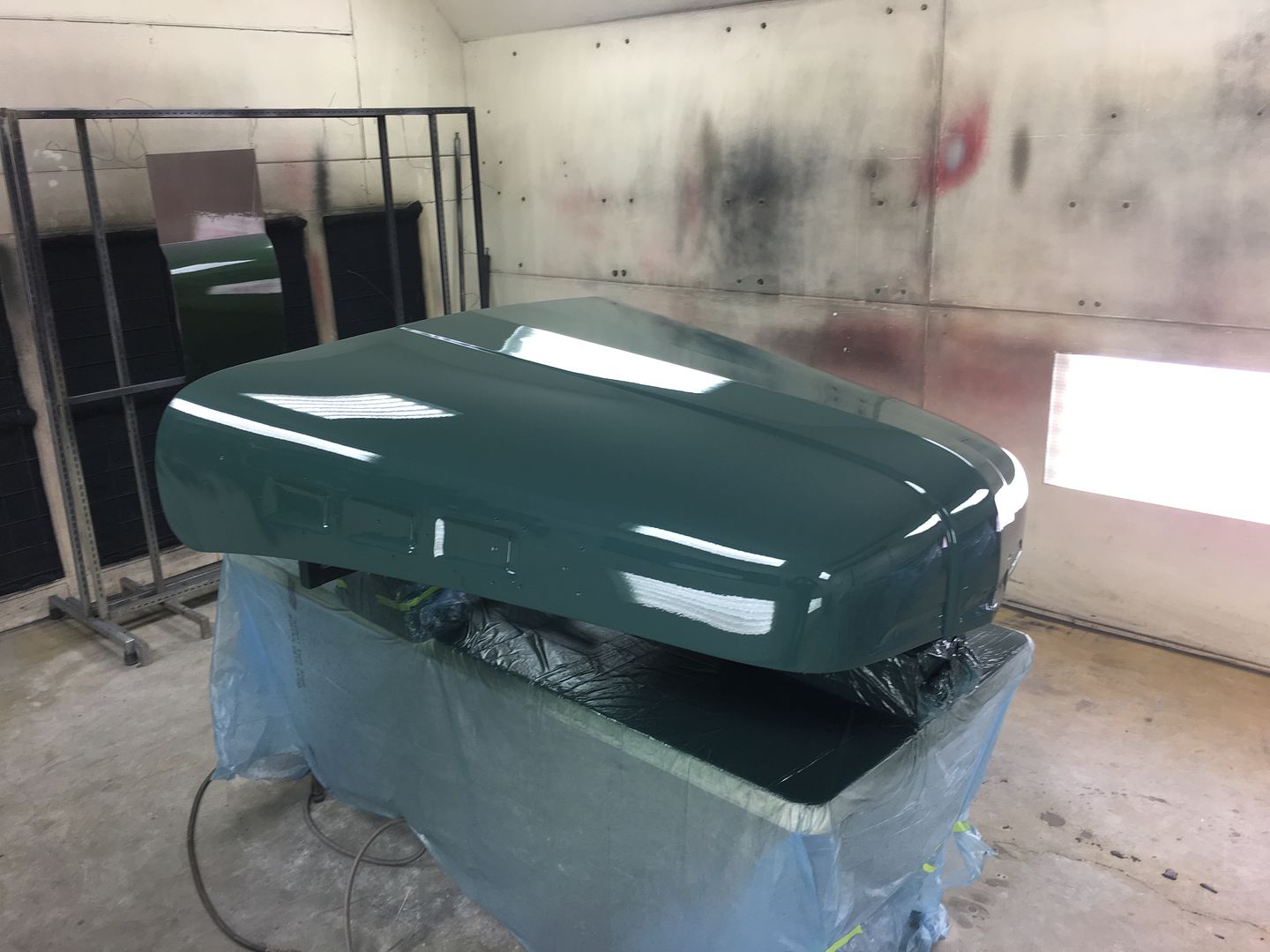
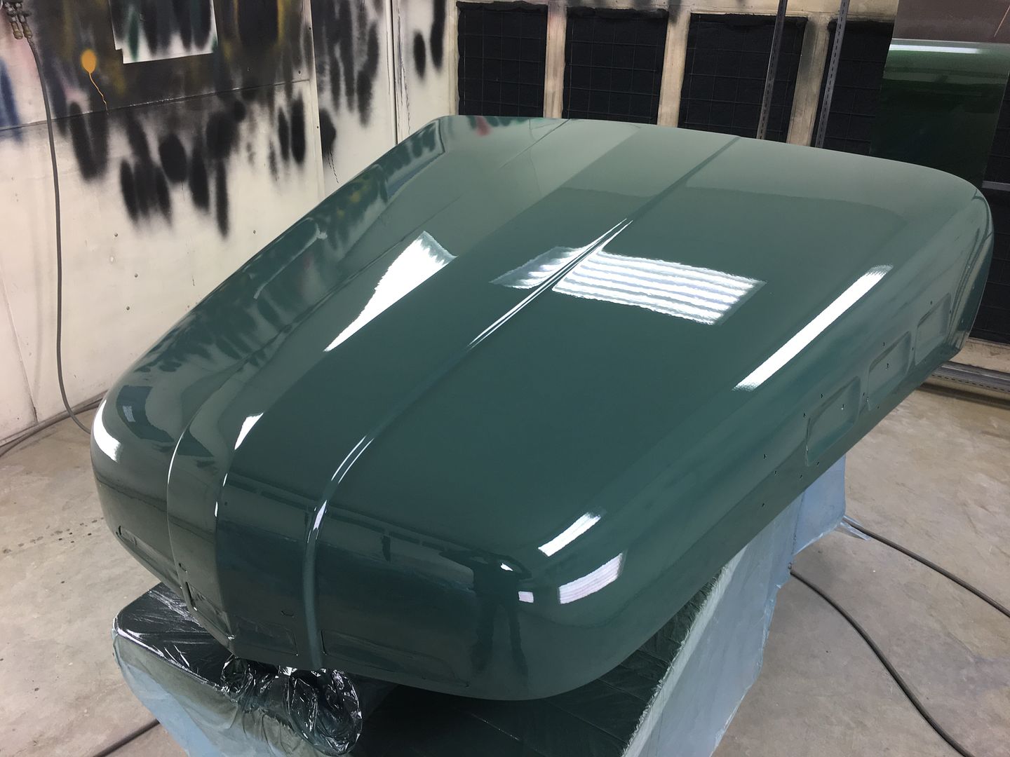
Fleet paint that was used originally on the truck, supplied by owner. Orange peel in a can..
2 coats of color, 2 coats of SPI Universal Clear...
Large 5/8" bolt through the hood latch hole for supporting the nose...
And going through our scrap inventory, here's some tubing we used for the back end, bolted into the hinge support. The extra "feet" help to stabilize it so the sanding effort won't try and flop it over...
With that done, all our open holes are taped over and the entire bottom side masked off to protect the inside finish..
A bit of Evercoat 416 to address some lows, and 3 coats of SPI epoxy for the next round of blocking on the outside.
Blocking...
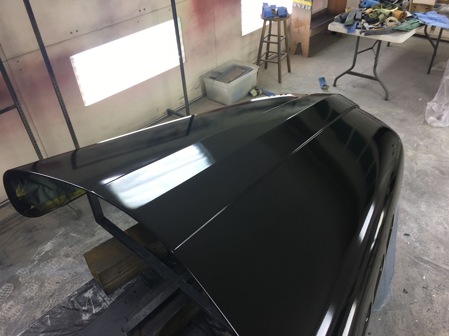
Some booth clean up and fresh masking on the table, hood pre-cleaned and tacked.....
Sealed with SPI Epoxy thinned about 10%
Fleet paint that was used originally on the truck, supplied by owner. Orange peel in a can..
2 coats of color, 2 coats of SPI Universal Clear...