When you click on links to various merchants on this site and make a purchase, this can result in this site earning a commission. Affiliate programs and affiliations include, but are not limited to, the eBay Partner Network.
I ordered dual alternators on my 7.3 F350. Probably more than I need. But I haul a truck camper, and the more power available, the better. Nice to have a backup too.
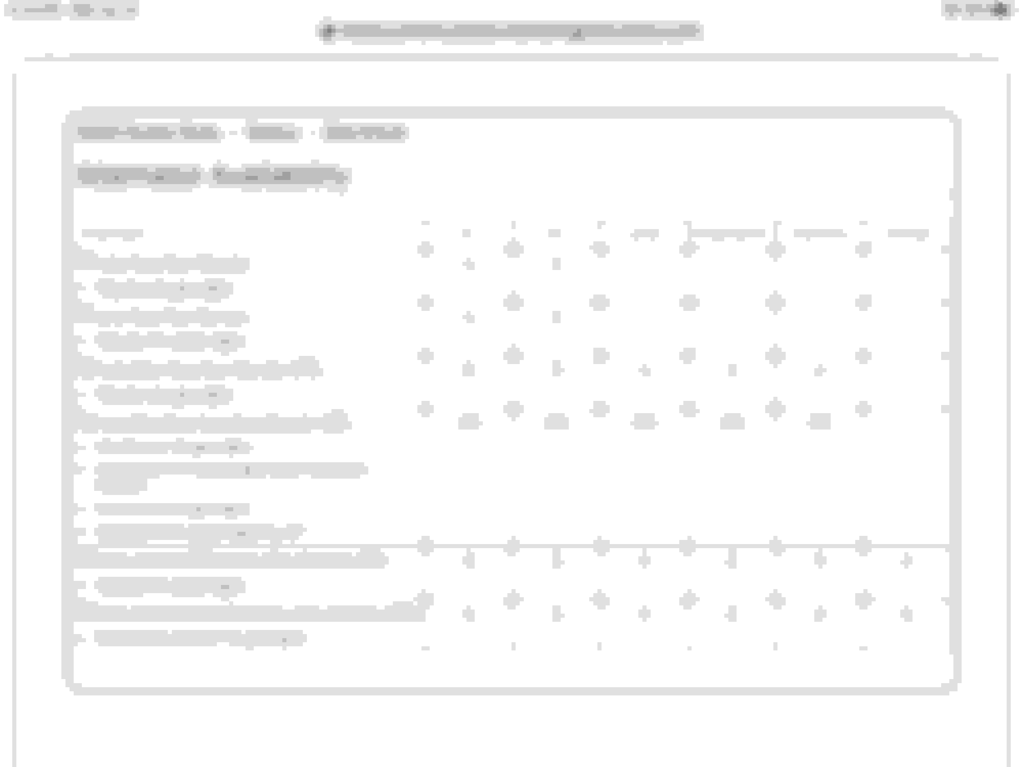
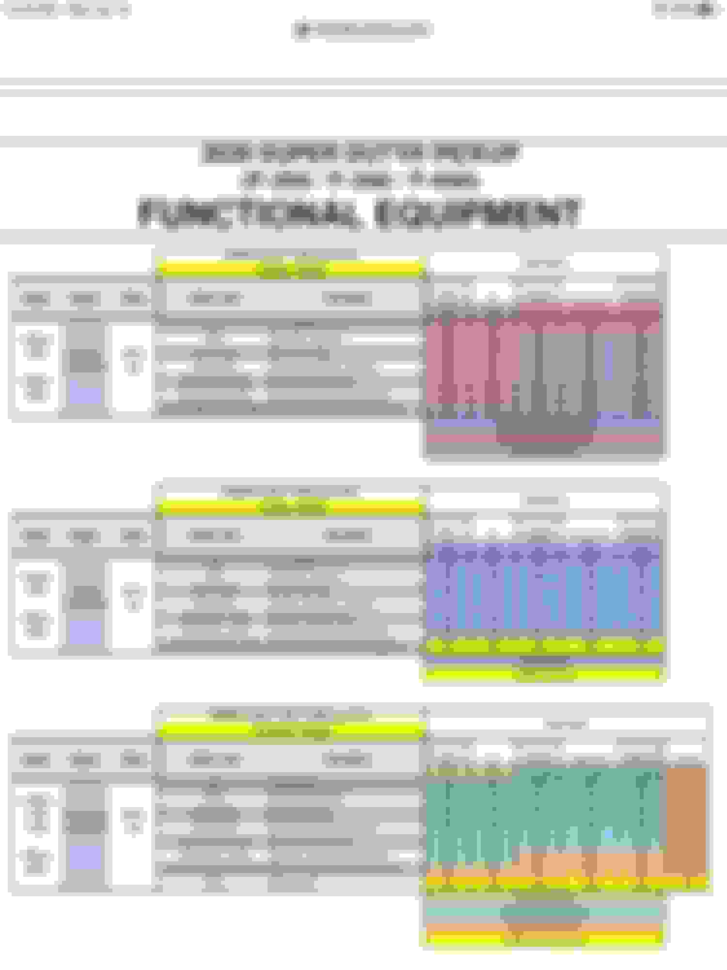
Here are charts describing MY2020 alternator availability and applications. The Dual 332 is a 175 + 157 combo, and the Dual 397 is a 220 + 157 combo.
Note that the alternator ratings are based on 80 F temperature and ~2,000 rpm engine speed. Output at higher temperatures (typical under-hood can be 200 F or more) or lower engine speed will be lower.
HTH,
Jim / crewzer
397 amp system = 240 + 157. I'm going to use your chart to help someone out. Thanks
1) you don't need up fitter switches. You can order it without them, as I did.
2) I have noticed no difference in mileage compared to with what others reported.
3) I have seen Dyno charts with the front end equipment both on and off the 7.3.... without the frontend the 7.3 runs just over 500hp. The water pump, alternator and such rob close to 78hp from that engine giving it a rating of 435hp. The drive train Robs another 17% to the rear wheels.
(1) 397 amp alternator. 2 batteries. I have this option. Not 2 alternators..... Just to be clear. Unless I'm missing something? If so, i'm going outside right now to look for that 2nd alternator!!
Put eyes on it for confirmation. I thought it was one alternator also when looking at the 2021 order guide.
I did not know there were 2 alternators..... Thought it was 1 huge 1.....
Now you know. Based on the discussions I've read here, you don't really have 397 amps available. While that would be cool for bragging rights, my understanding is that only one alternator operates at a time. The system "alternates" between them, allowing one to cool down.
Now you know. Based on the discussions I've read here, you don't really have 397 amps available. While that would be cool for bragging rights, my understanding is that only one alternator operates at a time. The system "alternates" between them, allowing one to cool down.
that�s what I thought as well
and does �operating� mean at smart voltage in
it gets more confusing when you try to follow which one is in smart mode and what that means and which one is in dumb mode and what that means.
Just to add some info, in a dual setup, they do not switch back and forth to rest one at a time. There is a main alternator that is always active and the other sits idle until the draw on the system is enough to activate it.
From Workshop Manual: Principles of Operation The PCM controlled single/dual charging system determines the optimal voltage setpoint for the charging system and communicates this information to the voltage regulator. This system is unique in that it has 2 communication lines between the PCM and the generator/regulator. Both of these communication lines are pulse-width modulated (PWM). The generator communication (GENCOM) line communicates the desired setpoint from the PCM to the voltage regulator. The generator monitor (GENMON) line communicates the generator load and error conditions to the PCM. The third pin on the voltage regulator, the A circuit pin, is a dedicated battery voltage sense line. The generator charges the battery and at the same time supplies power for all of the electrical loads that are required. The battery is more effectively charged with a higher voltage when the battery is cold and a lower voltage when the battery is warm. The PCM is able to adjust the charging voltage according to the battery temperature by using a signal from the intake air temperature (IAT) sensor. This means the voltage setpoint is calculated by the PCM and communicated to the regulator by the GENCOM circuit. The PCM simultaneously controls and monitors the output of the generator. When the current consumption is high or the battery is discharged the PCM raises engine speed to increase generator output. In dual generator systems, the PCM keeps the secondary generator in a standby state where it does not generate current unless the primary generator is generating full power and more current is needed to support the vehicle loads. The PCM monitors the output of the primary generator and adjusts the control setpoint of the secondary generator to cause it to provide additional current when needed. To minimize the engine drag when starting the engine, the PCM does not allow the generator to produce any output until the engine has started. The PCM turns off the generator during cranking to reduce the starter load and improve cranking speed. Once the engine starts, the PCM slowly increases generator output to help establish a stable engine speed. The PCM controls the charging system warning indicator by sending a message over the high speed CAN to the instrument cluster (IC). The PCM turns the charging system warning indicator off when generator output begins. The charging system warning indicator is also illuminated by the PCM whenever the key is ON with the engine OFF.
Thanks! That's good to know. I was operating under incorrect information.


 12-31-2020, 07:07 AM