Notices
1987 - 1996 F150 & Larger F-Series Trucks 1987 - 1996 Ford F-150, F-250, F-350 and larger pickups - including the 1997 heavy-duty F250/F350+ trucks
Sponsored by:
Sponsored by:

1988 F150 302 no timing advance

Thread Tools
 
Search this Thread
 
  #16  
Old 01-26-2019, 05:09 PM
vjsimone's Avatar
vjsimone
vjsimone is offline
Cargo Master
Join Date: Jun 2013
Location: Somewhere n North America
Posts: 3,168
Received 11 Likes on 9 Posts
Originally Posted by HungOverSheep
Do you have a pinout diagram to find pin 36? I managed to find it the fist time but I was guessing until I found it with the beep test on my DVM.
See attached;
 
Attached Images   
  #17  
Old 01-26-2019, 05:29 PM
vjsimone's Avatar
vjsimone
vjsimone is offline
Cargo Master
Join Date: Jun 2013
Location: Somewhere n North America
Posts: 3,168
Received 11 Likes on 9 Posts
Originally Posted by HungOverSheep
Originally Posted by vjsimone
Measure the dc voltage on the single (STI) Self-Test IN connector, you should have 5 volts dc.
okay, will do that once back to the truck Monday. Did I miss something about using a test light while hooking things up?
Grounding the STI 5v line is what initiates the Self-Test, if the 5v is not present, the wire is broken or the 5v power supply in the EECM has failed.

I suggest you try it this way if the 5v is present;
 
Attached Images  
  #18  
Old 01-26-2019, 06:00 PM
HungOverSheep's Avatar
HungOverSheep
HungOverSheep is offline
Junior User
Thread Starter
Join Date: Mar 2014
Posts: 91
Likes: 0
Received 0 Likes on 0 Posts
Originally Posted by vjsimone
Grounding the STI 5v line is what initiates the Self-Test, if the 5v is not present, the wire is broken or the 5v power supply in the EECM has failed.

I suggest you try it this way if the 5v is present;
I will do it this way, I am assuming I just count the meter bumbs? I do have an analog meter thankfully.
 
  #19  
Old 01-26-2019, 06:01 PM
HungOverSheep's Avatar
HungOverSheep
HungOverSheep is offline
Junior User
Thread Starter
Join Date: Mar 2014
Posts: 91
Likes: 0
Received 0 Likes on 0 Posts
Originally Posted by vjsimone
See attached;
Thank you very much, will report my findings soon.
 
  #20  
Old 01-26-2019, 06:02 PM
HungOverSheep's Avatar
HungOverSheep
HungOverSheep is offline
Junior User
Thread Starter
Join Date: Mar 2014
Posts: 91
Likes: 0
Received 0 Likes on 0 Posts
Originally Posted by Conanski
Given the year of the truck it is entirely possible some caps in the PCM have leaked and damaged "stuff" which means it needs to be replaced. Timing should advance to 16-20 degrees at idle for sure and will spike up into the 30 deg range with throttle.
Could the PCM still start the truck but not advance the timing? Like a partial failure.
 
  #21  
Old 01-26-2019, 06:11 PM
vjsimone's Avatar
vjsimone
vjsimone is offline
Cargo Master
Join Date: Jun 2013
Location: Somewhere n North America
Posts: 3,168
Received 11 Likes on 9 Posts
Originally Posted by HungOverSheep
Would it help any of you helpful members if I posted a video of what's going on while the truck is running?
Photos and video are always good, sometimes the lads will spot something.

If you remove your EECM, photo what you see inside, also photo all the numbers, letters and code on the outside. If you need to get another, that information will help, plus you want to capture in the case it is original. You will lose that info if you surrender your EECM as a core. There is the possibility that the EECM is not original to the truck, so there could be an issue there.

Take a look for a calibration code on the valve covers or driver’s door pillar for something like; 8-53F-R10
 
  #22  
Old 01-26-2019, 06:13 PM
vjsimone's Avatar
vjsimone
vjsimone is offline
Cargo Master
Join Date: Jun 2013
Location: Somewhere n North America
Posts: 3,168
Received 11 Likes on 9 Posts
Originally Posted by HungOverSheep
Could the PCM still start the truck but not advance the timing? Like a partial failure.
Yes. There is some design in the EECM to help you get home in some cases...
Like the Default 10deg the TFI/ICM uses if there is no SpOut present...

The truck starts using the 10 deg, then the Spout signal supplied by the EECM is modified depending on other sensor inputs to the EECM. Then the spout signal leading edge is compared to the PIP signal and the Timing adjustment is made as adjusted output to the coil switching.
 
  #23  
Old 01-26-2019, 06:31 PM
vjsimone's Avatar
vjsimone
vjsimone is offline
Cargo Master
Join Date: Jun 2013
Location: Somewhere n North America
Posts: 3,168
Received 11 Likes on 9 Posts
Originally Posted by HungOverSheep
I will do it this way, I am assuming I just count the meter bumbs? I do have an analog meter thankfully.
Yeah, meter bumps, select a low dcv setting.
You could use a 12 volt light as well.
Checking it at the ODB1 connector postpones troubleshooting the CEL path.

Seems, from memory, when that light stays lit, you have a failure in the EECM.
 
  #24  
Old 01-26-2019, 07:26 PM
HungOverSheep's Avatar
HungOverSheep
HungOverSheep is offline
Junior User
Thread Starter
Join Date: Mar 2014
Posts: 91
Likes: 0
Received 0 Likes on 0 Posts
Originally Posted by vjsimone
Photos and video are always good, sometimes the lads will spot something.

If you remove your EECM, photo what you see inside, also photo all the numbers, letters and code on the outside. If you need to get another, that information will help, plus you want to capture in the case it is original. You will lose that info if you surrender your EECM as a core. There is the possibility that the EECM is not original to the truck, so there could be an issue there.

Take a look for a calibration code on the valve covers or driver’s door pillar for something like; 8-53F-R10
I will take plenty of pictures Monday to help out, that's why I'm really suck. I took note (when I unbolted the EECM harness) that the EECM actually appeared loose, almost unbolted from the frame. I didn't bother looking any more though.
 
  #25  
Old 01-26-2019, 07:27 PM
HungOverSheep's Avatar
HungOverSheep
HungOverSheep is offline
Junior User
Thread Starter
Join Date: Mar 2014
Posts: 91
Likes: 0
Received 0 Likes on 0 Posts
Originally Posted by vjsimone
Yeah, meter bumps, select a low dcv setting.
You could use a 12 volt light as well.
Checking it at the ODB1 connector postpones troubleshooting the CEL path.

Seems, from memory, when that light stays lit, you have a failure in the EECM.
I will pull the codes on Monday and report back, thank you.
 
  #26  
Old 01-26-2019, 07:28 PM
HungOverSheep's Avatar
HungOverSheep
HungOverSheep is offline
Junior User
Thread Starter
Join Date: Mar 2014
Posts: 91
Likes: 0
Received 0 Likes on 0 Posts
Originally Posted by vjsimone
Yes. There is some design in the EECM to help you get home in some cases...
Like the Default 10deg the TFI/ICM uses if there is no SpOut present...

The truck starts using the 10 deg, then the Spout signal supplied by the EECM is modified depending on other sensor inputs to the EECM. Then the spout signal leading edge is compared to the PIP signal and the Timing adjustment is made as adjusted output to the coil switching.
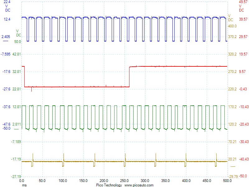
Is is there a method to test the spout output signal? I do have an old oscilloscope but I am not sure if it is functioning correctly. What should the spout output signal voltage be if anything? Also, is there a default voltage setting up the spout output connector that I should be looking for?
 
  #27  
Old 01-26-2019, 07:51 PM
vjsimone's Avatar
vjsimone
vjsimone is offline
Cargo Master
Join Date: Jun 2013
Location: Somewhere n North America
Posts: 3,168
Received 11 Likes on 9 Posts
Originally Posted by HungOverSheep
What should the spout output signal voltage be if anything?
Ideally a square wave shown in this attachment. Ignore the wire colors. follow the PIP from the TFI to the EECM, and the Spout from the EECM to the TFI.
 
Attached Images  
  #28  
Old 01-26-2019, 08:16 PM
vjsimone's Avatar
vjsimone
vjsimone is offline
Cargo Master
Join Date: Jun 2013
Location: Somewhere n North America
Posts: 3,168
Received 11 Likes on 9 Posts
Originally Posted by HungOverSheep
Is is there a method to test the spout output signal? I do have an old oscilloscope but I am not sure if it is functioning correctly.
I believe the Green Trace is the PIP and the Blue Trace is the Spout;


  #29  
Old 01-26-2019, 08:20 PM
HungOverSheep's Avatar
HungOverSheep
HungOverSheep is offline
Junior User
Thread Starter
Join Date: Mar 2014
Posts: 91
Likes: 0
Received 0 Likes on 0 Posts
Originally Posted by vjsimone
Ideally a square wave shown in this attachment.
Great information there, thank you. So essentially, if I can prove that the TFI is outputting a square wave to the EECM via the SPOUT connecter and the timing is not changing then that concludes something is wrong with the EECM?
 
  #30  
Old 01-26-2019, 08:33 PM
vjsimone's Avatar
vjsimone
vjsimone is offline
Cargo Master
Join Date: Jun 2013
Location: Somewhere n North America
Posts: 3,168
Received 11 Likes on 9 Posts
Originally Posted by HungOverSheep
Great information there, thank you. So essentially, if I can prove that the TFI is outputting a square wave to the EECM via the SPOUT connecter and the timing is not changing then that concludes something is wrong with the EECM?
Well the fact that your engine is running proves PIP output to the EECM, and you can see that on the Neg coil wire switching.
The TFI outputs the PIP square wave to the EECM pin 56.
The EECM pin 36 outputs the Spout square wave via the Spout Connector back to the TFI. If this is not happening, then it is usually an issue with the EECM. Most likely the 5v power supply capacitors.


Quick Reply: 1988 F150 302 no timing advance


All times are GMT -5. The time now is 06:18 AM.