
C6 to a ZF5--All the small stuff.
#61
 09-29-2018, 07:32 PM

I spent 4 hours rigging up a home-made puller on my slide hammer. Man, I hammered and hammered, and did not get that ... race to move one hair! Then I walked into AutoZone and found that they had the exact puller I needed, with a heavier slide on the slide hammer! And, it was FREE! I paid $125 that is refunded if I return it within 90 days. Sweet. I can't wait to try it.
#62
10-01-2018, 10:40 AM
You guys will laugh about my custom mods to the puller:
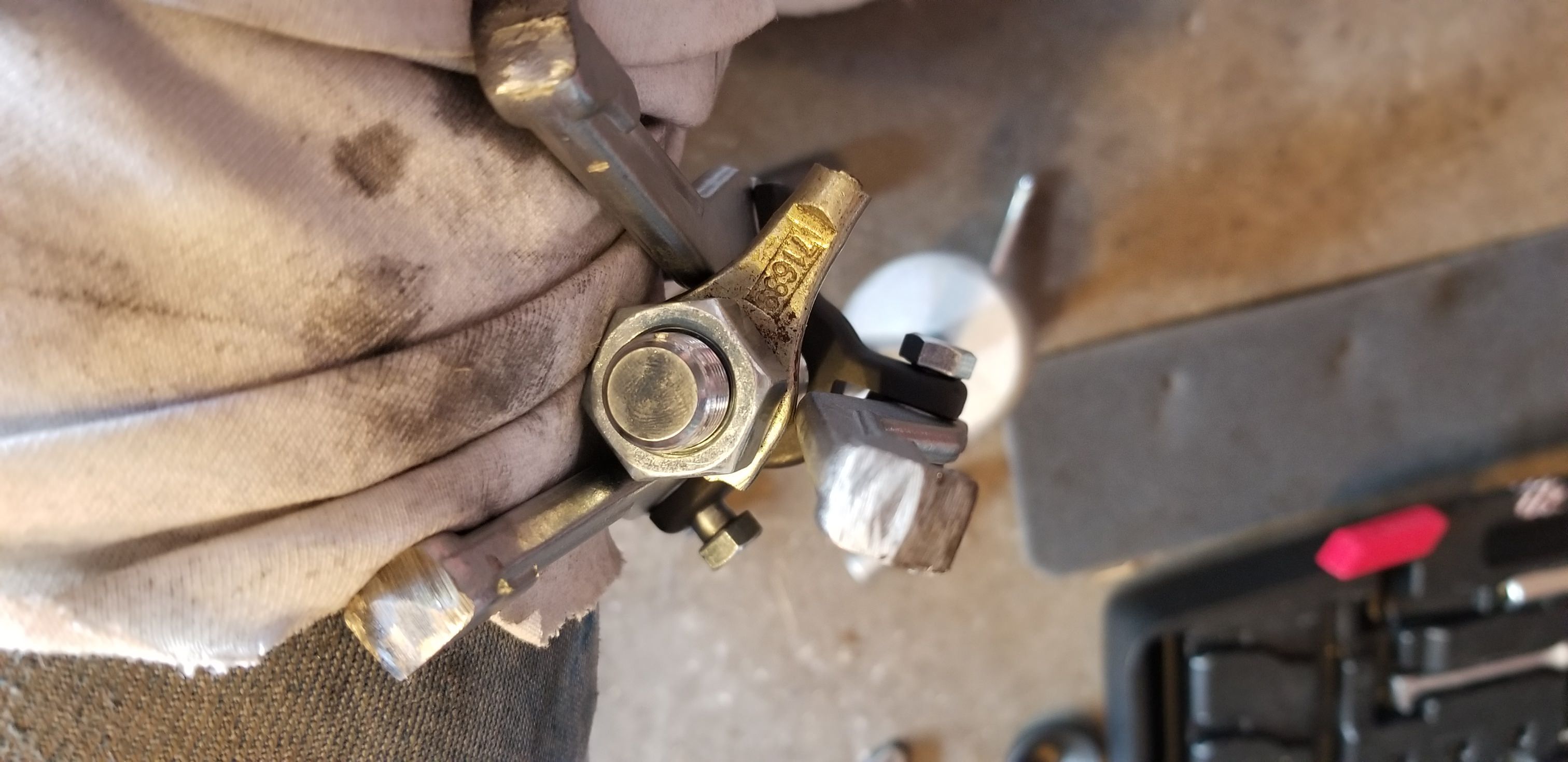
Yeah, that is the brake pushrod eye off a v. booster. You can also see that I had to grind down the tip of each arm to get it to hook the race. But man, what a difference having the proper tool makes. I had to sit on the case while using the slide hammer. To install the new race, which is actually different size than the existing Timken race, I first put in in the freezer for 20 minutes. I was glad to have the slide hammer because I took it apart and used the heave cylindrical slide weight as a hammer inside the zf case, and hammered the new race in place. It installs below the surface of the case. Use the old race atop the new one and hammer on it. You can tell when it has bottomed out from the sound and feel when you hammer. The first time you install the new race, put it in without the oil baffle or shim. Make sure it is seated, then put the case back on the trans. Measure how far either the pilot shaft or output shaft moves when you apply pressure on the other shaft. I had .058" movement. According to the book, I could have between .00079 and .00434. My oil baffle measured .012. Since I had .058, which is fifty-eight thousandths, and my oil baffle is twelve thousandths, I subtracted twelve from 58, and that left 46 thousandths of an inch of an inch play. I thought that if ended up with 2 thousandths play, that would put me in the required specs. So, I needed a shim, or shims, that totaled forty-four thousandths of an inch.
The one I removed was 58/1000's. On ebay I found a shim kit, part ## E7TZ-7029-A by Ford, for $30, and ordered it.
And, since the repair sleeve that I tried to install to make my p.shaft not leak around the seal tore up the seal, I believe I will order a new p. shaft. If I can find one not made in China. Beware: there are several length p.shafts, so get the proper one for your engine. Below you can see what sitting does to a trans:
Attachment 283346
In the photo below, you can see why you always order a new oil baffle when you change the bearing race. The baffle gets destroyed when you install the slide hammer puller.
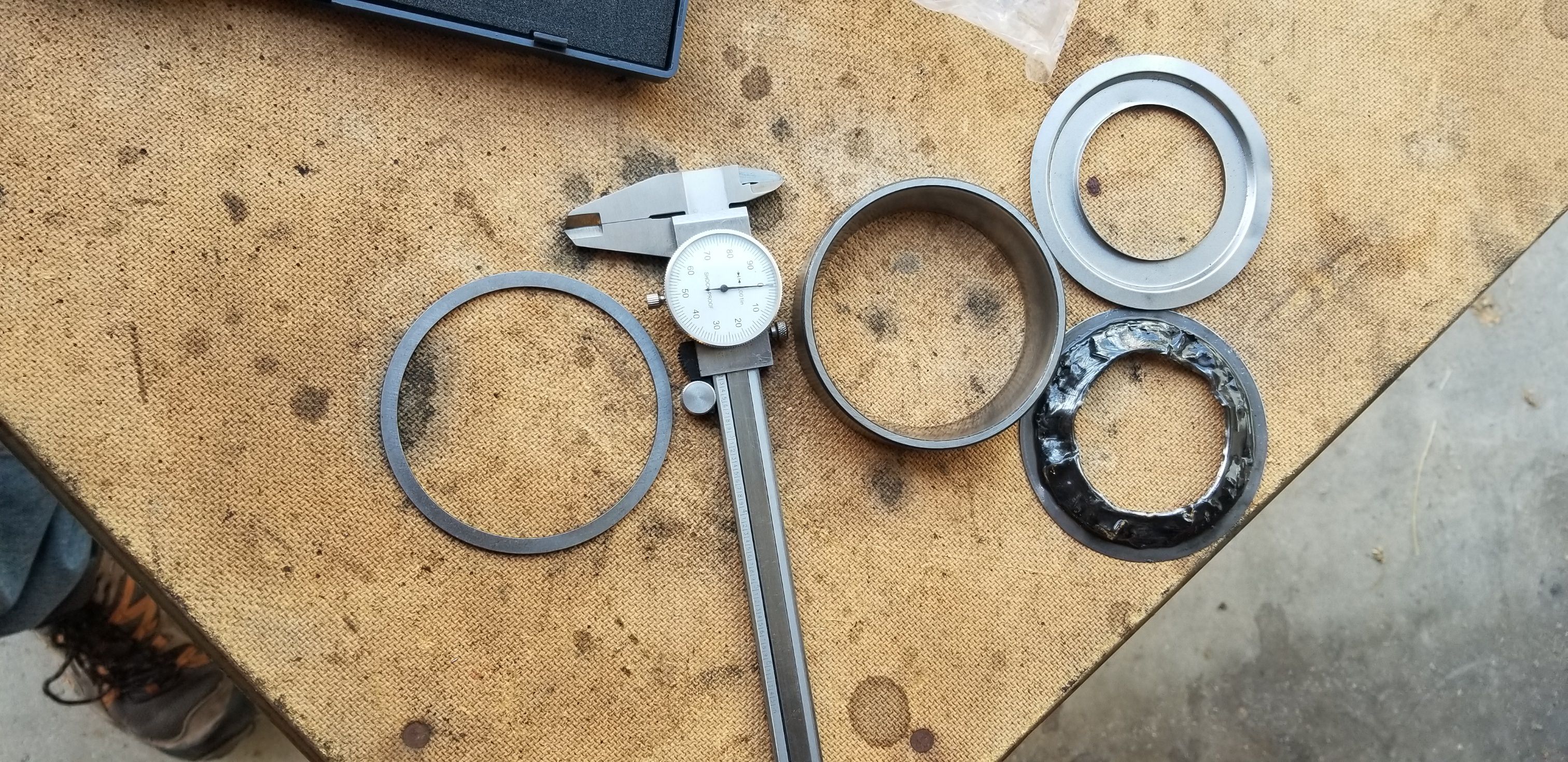
Above, on the right, one above the other, is the old and new oil baffle. They measure .012". Beside the two baffles is the old bearing race. Use it set on top of the new race, to hammer the new one in place. On the left is the .058" shim that was under the old race.
Yeah, that is the brake pushrod eye off a v. booster. You can also see that I had to grind down the tip of each arm to get it to hook the race. But man, what a difference having the proper tool makes. I had to sit on the case while using the slide hammer. To install the new race, which is actually different size than the existing Timken race, I first put in in the freezer for 20 minutes. I was glad to have the slide hammer because I took it apart and used the heave cylindrical slide weight as a hammer inside the zf case, and hammered the new race in place. It installs below the surface of the case. Use the old race atop the new one and hammer on it. You can tell when it has bottomed out from the sound and feel when you hammer. The first time you install the new race, put it in without the oil baffle or shim. Make sure it is seated, then put the case back on the trans. Measure how far either the pilot shaft or output shaft moves when you apply pressure on the other shaft. I had .058" movement. According to the book, I could have between .00079 and .00434. My oil baffle measured .012. Since I had .058, which is fifty-eight thousandths, and my oil baffle is twelve thousandths, I subtracted twelve from 58, and that left 46 thousandths of an inch of an inch play. I thought that if ended up with 2 thousandths play, that would put me in the required specs. So, I needed a shim, or shims, that totaled forty-four thousandths of an inch.
The one I removed was 58/1000's. On ebay I found a shim kit, part ## E7TZ-7029-A by Ford, for $30, and ordered it.
And, since the repair sleeve that I tried to install to make my p.shaft not leak around the seal tore up the seal, I believe I will order a new p. shaft. If I can find one not made in China. Beware: there are several length p.shafts, so get the proper one for your engine. Below you can see what sitting does to a trans:
Attachment 283346
In the photo below, you can see why you always order a new oil baffle when you change the bearing race. The baffle gets destroyed when you install the slide hammer puller.
Above, on the right, one above the other, is the old and new oil baffle. They measure .012". Beside the two baffles is the old bearing race. Use it set on top of the new race, to hammer the new one in place. On the left is the .058" shim that was under the old race.
#63
10-01-2018, 11:45 AM

#64
10-01-2018, 04:46 PM
#65
10-02-2018, 09:51 AM
HitmanX over on the OBS powerstroke section just did this same thing. You might see if you can track down his trans build thread to make sure everything is covered. He's got the factory ZF manual and I'm sure he would be willing to look something up for you if you had any questions.
#66
10-03-2018, 05:13 PM
#67
10-05-2018, 10:46 AM
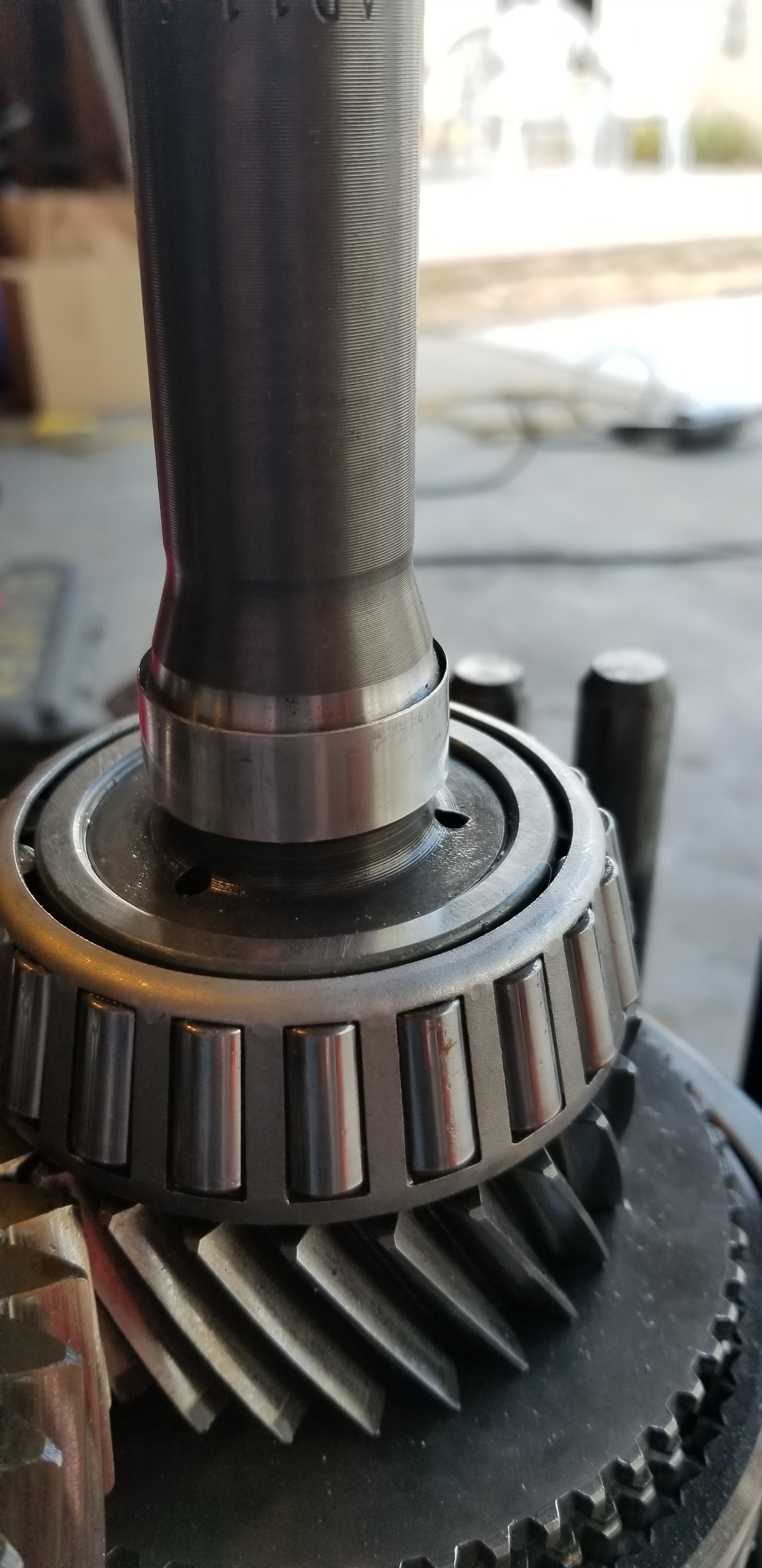
The shim kit arrived and I set to work. The zf, has .070 play without any shims between the bearing and the housing. The oil baffle that goes in there is .012. So, I just had to find a shim that was a couple of thousandths thinner than .058. Luckily, a .056 shim came in the kit, so I installed that one and ended with .002 play, which is right in the middle of the book tolerances or specs. In the photo below you can see the counter shaft race and the seat where the mail shaft race sits. It is removed in the photo.
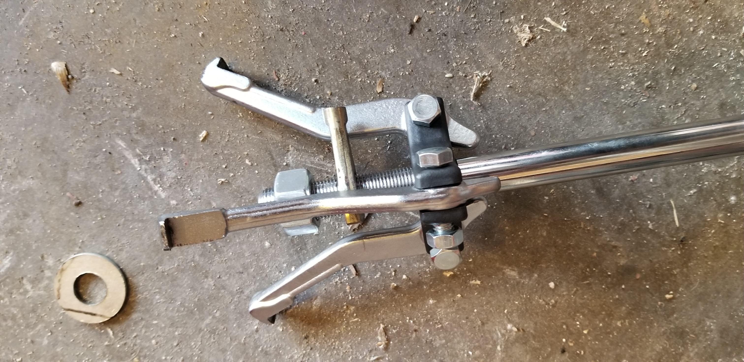
Autozone has a bearing puller kit that works to pull the main shaft race. You have to grind down the tip of each of the three legs of the puller for them to get under the race. I did that, and there was no problem returning it. Use the old race, on top of the new one, and use the slide hammer weight from the puller, to hammer the race into place. It has to bottom out. You can tell when it hits bottom. It sounds and feels different when you hit it with the weight. In the photo below you can see how I ground down the tip of each leg of the puller. They were pointed before, and the part that goes beneath the race was thicker and would not get under the race. I also had to use a flat blade screw driver and hammer and tap down the oil baffle beneath the race to allow the puller to get beneath the race.
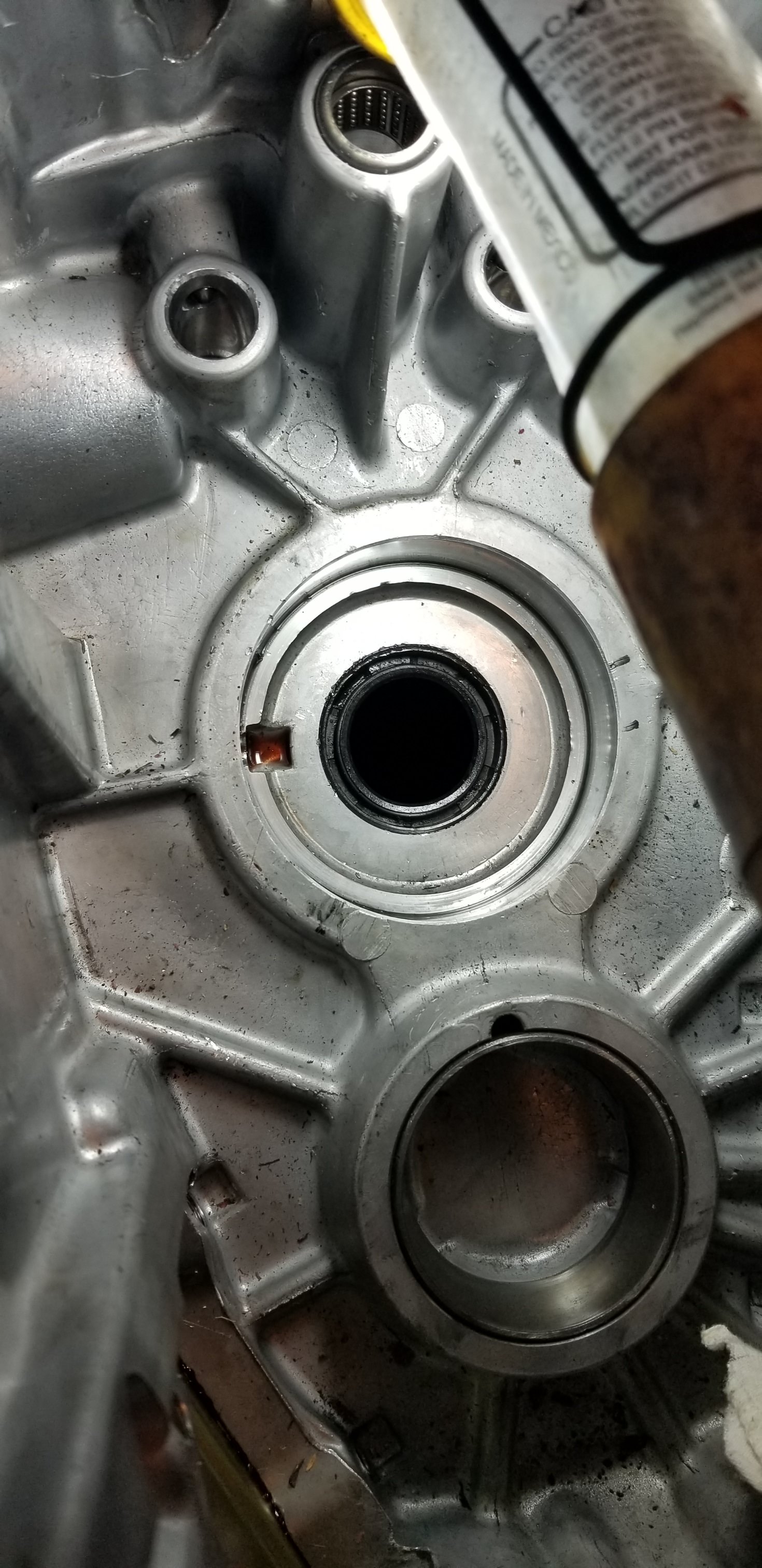
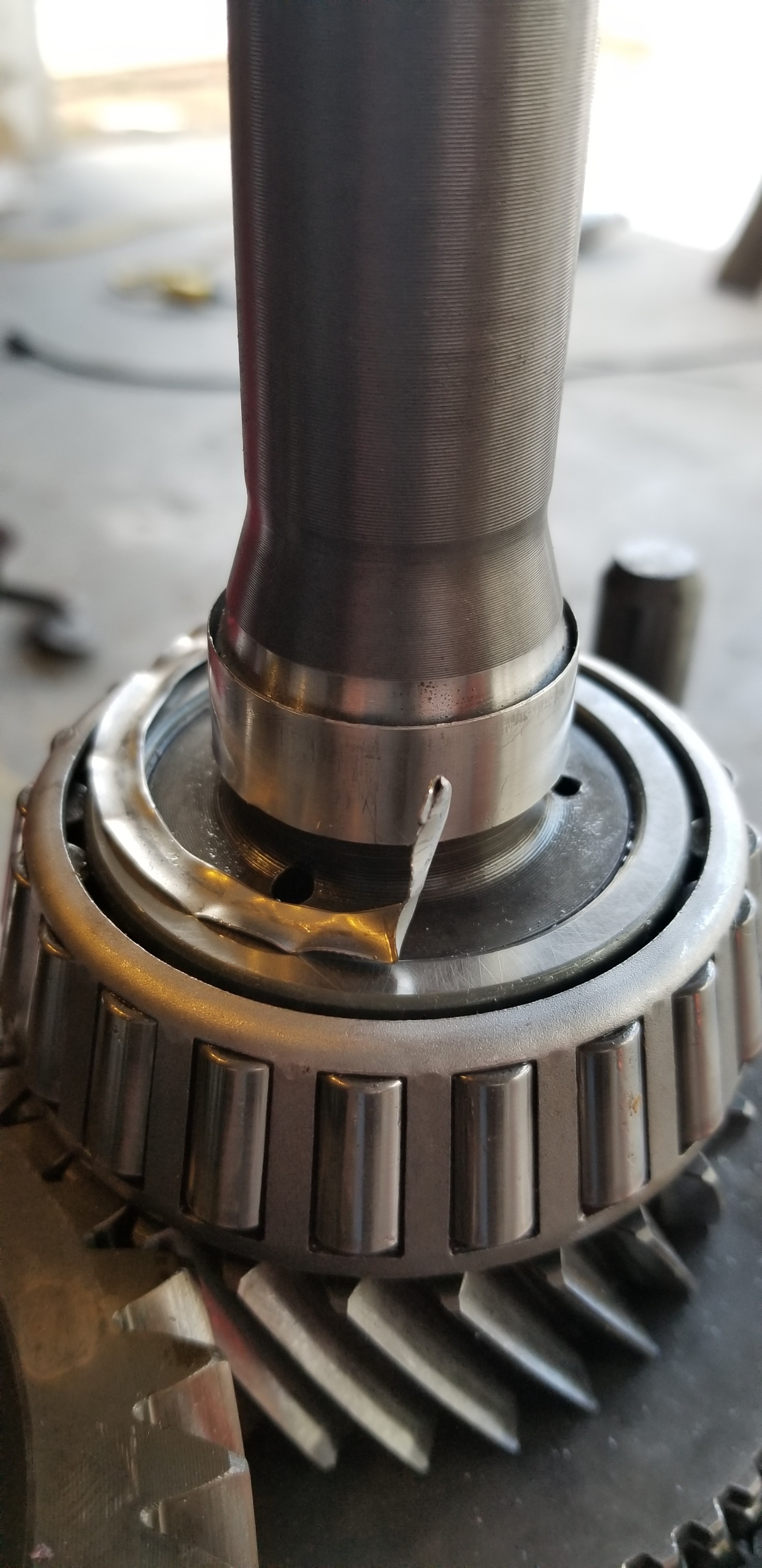
In the photo below, you can see the blemish I'll be covering with a spedi-sleeve. Talk about a witness mark, right? I was going to replace the input shaft, but none of the places selling them would divulge where the hell their 'after market' shaft was made. That mean China. And of course, that means inferior. So I chose to keep my ZF stamped shaft. I had to find a tube long enough to go over the spline so I could hammer the sleeve into place. I used sleeve (a National part) #99139, from Rockauto for $19 plus postage.
Attachment 283346
And below is the spedi-sleeve. You slip it over the shaft, slip something over it that rests on the flange, and tap it into place. I took a file and beveled the top edge so it would slide right through the seal. Before it is put on, you have to snip the flange to the indented line. Then, when it is in place, you take a pair of needle-nose pliers and roll the flage back from the snip, and peal it off, leaving a band around the input shaft where the seal sits. Be sure you get/order the sleeve for a zf. For the cost of an $18 repair, I was able to save $100--$260 for a new shaft. Plus, I know my shaft is quality.
Attachment 284512
Autozone has a bearing puller kit that works to pull the main shaft race. You have to grind down the tip of each of the three legs of the puller for them to get under the race. I did that, and there was no problem returning it. Use the old race, on top of the new one, and use the slide hammer weight from the puller, to hammer the race into place. It has to bottom out. You can tell when it hits bottom. It sounds and feels different when you hit it with the weight. In the photo below you can see how I ground down the tip of each leg of the puller. They were pointed before, and the part that goes beneath the race was thicker and would not get under the race. I also had to use a flat blade screw driver and hammer and tap down the oil baffle beneath the race to allow the puller to get beneath the race.
In the photo below, you can see the blemish I'll be covering with a spedi-sleeve. Talk about a witness mark, right? I was going to replace the input shaft, but none of the places selling them would divulge where the hell their 'after market' shaft was made. That mean China. And of course, that means inferior. So I chose to keep my ZF stamped shaft. I had to find a tube long enough to go over the spline so I could hammer the sleeve into place. I used sleeve (a National part) #99139, from Rockauto for $19 plus postage.
Attachment 283346
And below is the spedi-sleeve. You slip it over the shaft, slip something over it that rests on the flange, and tap it into place. I took a file and beveled the top edge so it would slide right through the seal. Before it is put on, you have to snip the flange to the indented line. Then, when it is in place, you take a pair of needle-nose pliers and roll the flage back from the snip, and peal it off, leaving a band around the input shaft where the seal sits. Be sure you get/order the sleeve for a zf. For the cost of an $18 repair, I was able to save $100--$260 for a new shaft. Plus, I know my shaft is quality.
Attachment 284512
#68
10-11-2018, 07:35 PM
I finally got some time to work on the zf. I installed the new sleeve. You have to snip through the flange with dykes or tin snips prior to installation. Once the sleeve is in position, you grab the flange and pull it off with a pair of needle nose or standard pliers.
Note that the sleeve rides above the taper of the pilot shaft. Some seals have two lips, one smaller than the other. The smaller ID lip of the seal is supposed to be pushed into the taper or bevel of the pilot shaft like a wedge. However, with the sleeve, it rides too high for that wedge effect to happen. But, it has a nice, slick, new surface to spin on. Hopefully that is the last time I have to change that seal. Having a seal r&r'ed from inside the case is idiocy. IMO. *Note: the Duralast seals from autozone looked to of higher quality than the National seals that cost more.
Above is a shot with the flange already pealed off and lying beside the redi-sleave.
#70
10-13-2018, 12:01 PM
When I got it all back together, I found there was zero vertical play in the pilot shaft as there was before the bearing change. So, I guess the procedure served a purpose. And, it was FUN.
Now, on to the other aspects of the install. Next, I plan to work on the pedal bracket mods that are needed for the hydro clutch. Below is a photo of what I'm going to weld up.
Attachment 284491
I'll be welding a bolt onto the clutch pedal as seen below. But before I do that, I have to make sure ABSOLUTELY SURE, that the pedal or clutch plunger will have 2.5" of travel. It MUST have that to work correctly.
Attachment 278266
So far, after changing out the oem bushings and installing bearings from mustangSteve dot com, for a much smoother pedal, below is what my assembly looks like so far.
Attachment 278412
Below is what I removed.
Attachment 278417
And here is what I installed for the clutch pedal to pivot from/on.
Attachment 278413
Where I can, I'm replacing the oem plastic eyes and plastic bushings with bearing. However, the brake pedal hangs on a tube through which the clutch pedal rod slides through. At each end of that tube, Ford installed plastic bushings. I wanted to replace those with a better alternative to plastic, but I was surprised when I pulled my 40+ year old pedal assembly from the junkyard, and found that those plastic oem bushings were still good. That told me everything, and I decided to stay with them. Below is a shot of the brake tube and the oem plastic bushings.
Attachment 278416
Above, the pedal on the right is the brake pedal. Below it you see a brass and plastic bushing. For the brass one to fit I'd have to take it to a machine shop and have it turned down. I can buy the plastic ones for $3.00 a pop, and they last 40 years. What would you do? This is an IQ test, ha ha.
#72
10-13-2018, 11:09 PM
I wanted to mention something that will save others a few bucks. When you go to take apart the zf5, before you remove the housing there are three small factory plugs in front of the shift tower that have to be taken out. All the other threads say to punch a hole in them or drill a hole and screw a screw or something through them, and yank them out. But you don't have to ruin them. Just tap them down with a punch, but put on eye protection first. Don't ask. These plugs look like 1/4 size freeze plugs, and they hold strong springs beneath them. Tap them down and they will begin to flip as you tap. Suddenly they shoot out. Rig up a towel above to stop/catch them. Remove the spring. When you go to reinstall them, grap each with a needle-nosed plier, and just roughen up the outside edge a bit to help them hold before reuse. Then reinstall with a nut driver, and tap in with the spring in place. That will save you $13, plus a wait for the new ones to arrive.Below is a photo of one of the plugs beside a spark plug.
Attachment 284470
#73
11-21-2018, 10:12 PM
I took a break from the trans stuff to work on the new engine. I'm building a bench to sit at when I finish porting the head. This year 300 head had odd ridges in the Combustion chambers that are shrouding my over-size valves badly, not to mention bumping the compression ratio and putting me into the expensive gas regions.
Attachment 284315
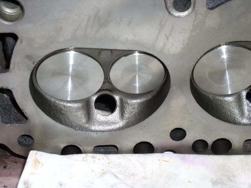
And below is the before and after pic.
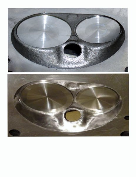
But the engine, 77 block, 96 crank, 65 rods, 351w pistons, 82 head, chebby over-size valves, one of a kind cam, DS2 dizzy through an msd box, summit tfi coil, shorty headers 6 into two, into 6' of 3" tube, into a FM 50 series, out the back with one 2.5" tube, so it doesn't sound ricey, and a Quadrajet custom carb, not to mention the ZF 5 speed.
The trans work should begin anew soon.
Attachment 284315
And below is the before and after pic.
But the engine, 77 block, 96 crank, 65 rods, 351w pistons, 82 head, chebby over-size valves, one of a kind cam, DS2 dizzy through an msd box, summit tfi coil, shorty headers 6 into two, into 6' of 3" tube, into a FM 50 series, out the back with one 2.5" tube, so it doesn't sound ricey, and a Quadrajet custom carb, not to mention the ZF 5 speed.
The trans work should begin anew soon.
#74
12-11-2018, 09:24 PM
I'm back, believe it or not! I have a week or so to swap the trans and do a few other projects. Today I stripped the interior. I removed the seat and belts and carpet and pads. Tomorrow I'll pull the S. column and pedal/column brace, and swap in the new pedal assembly for a manual with a clutch! A clutch! It's been a long time. Come to me. Dump the clutch, and oh yeah, I got it. Anyway, after changing the pilot shaft bearing and the pocket bearing, and all the seals, front and rear, the trans is tight. There is no play in the p.shaft, up and down. I like that. I have to install some dynamat for sound proofing. I think I'll go right up the back wall too, and do under the door panels too.
I should have several pix tomorrow.
Does anyone know if the spacer between the block and trans is universal? I only have the one for an auto trans, and plan to use that? Is that possible?
I should have several pix tomorrow.
Does anyone know if the spacer between the block and trans is universal? I only have the one for an auto trans, and plan to use that? Is that possible?
#75
12-13-2018, 09:51 AM
I removed the column, seat, carpet, and auto pedal assembly.
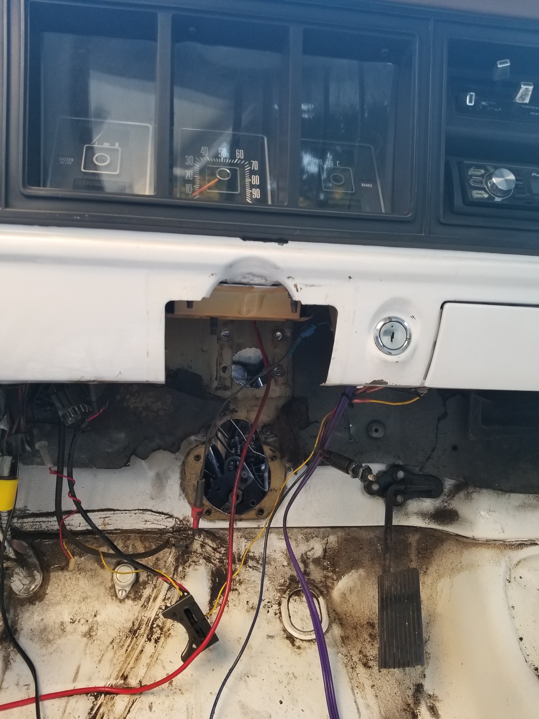
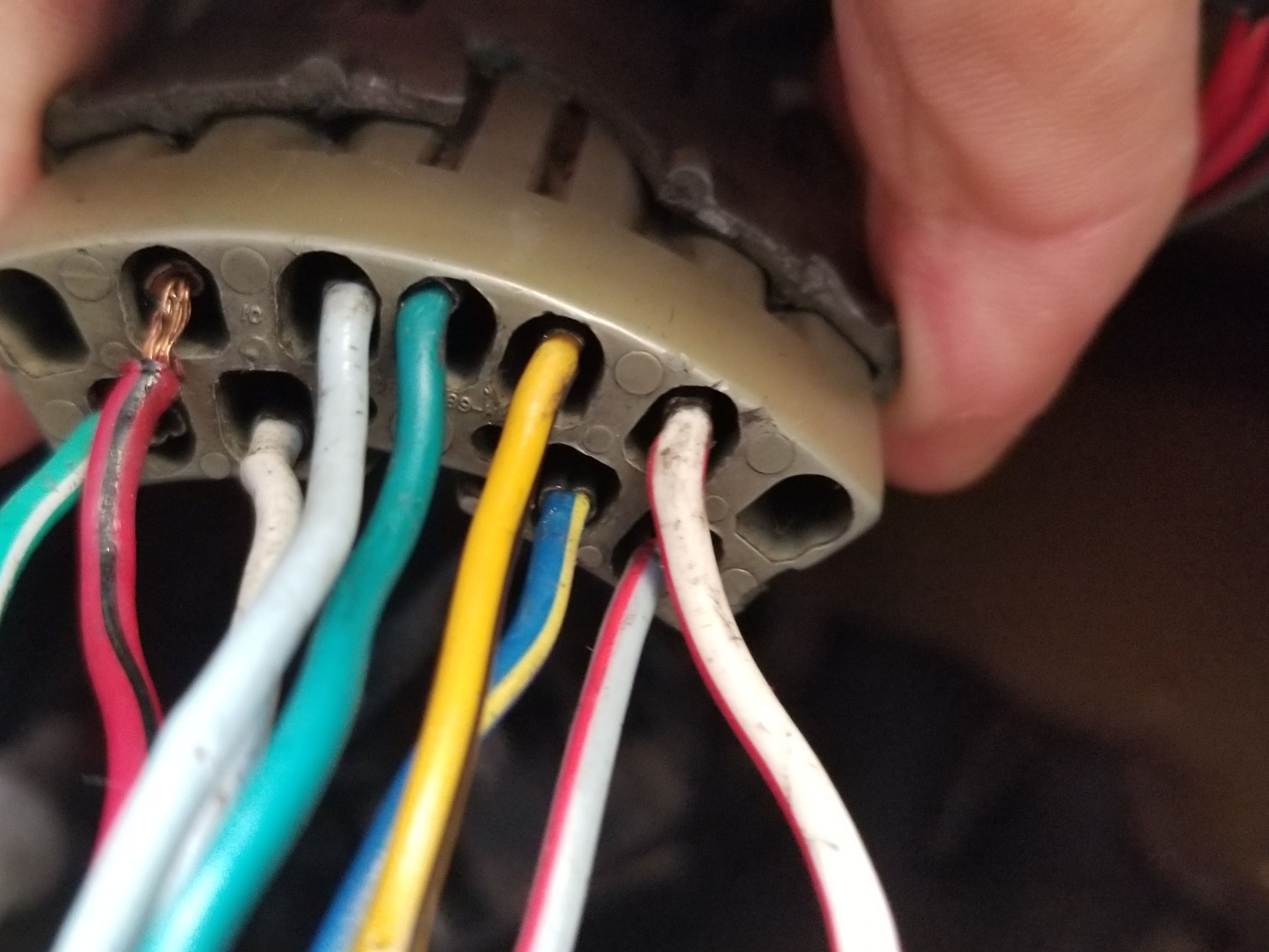
The plug from the column into the electrical is a bear to separate, and I broke it. LMC, here I come. I'll be sure to use some electrical grease before I put it back together.
I also found that my hydroboost unit was leaking, so I pulled it. It lasted 8 years. I used a hydro from a 94 Astro Van, and have decided to step up to one from a 99 F250 Super Duty with 7.3 Turbo Diesel. That will give me the Ford attachment. I'll only have to move the attachment bracket a bit from the firewall, to get the 5.65" oem length of the rod, so the pedal maintains its oem position. I'm going with the master for that model. With hydroboost, it is important that the master and the hydro mate correctly, or you might end up placing a rod in between to take up the slack, and with braking, I want to be confident every time I hit the pedal that all is well.
*Another point I'll make about hydroboost: It is very important that you have dual return lines, with dual returns into the pump, or you hinder flow and that will affect steering. You'll feel it in parking lots when on the brake and cranking the wheel. It will feel as though your p/s cuts out 75%. I got my Saginaw pump off a 78 LTD with a 460. The brackets can be taken off Econoline vans with your engine.
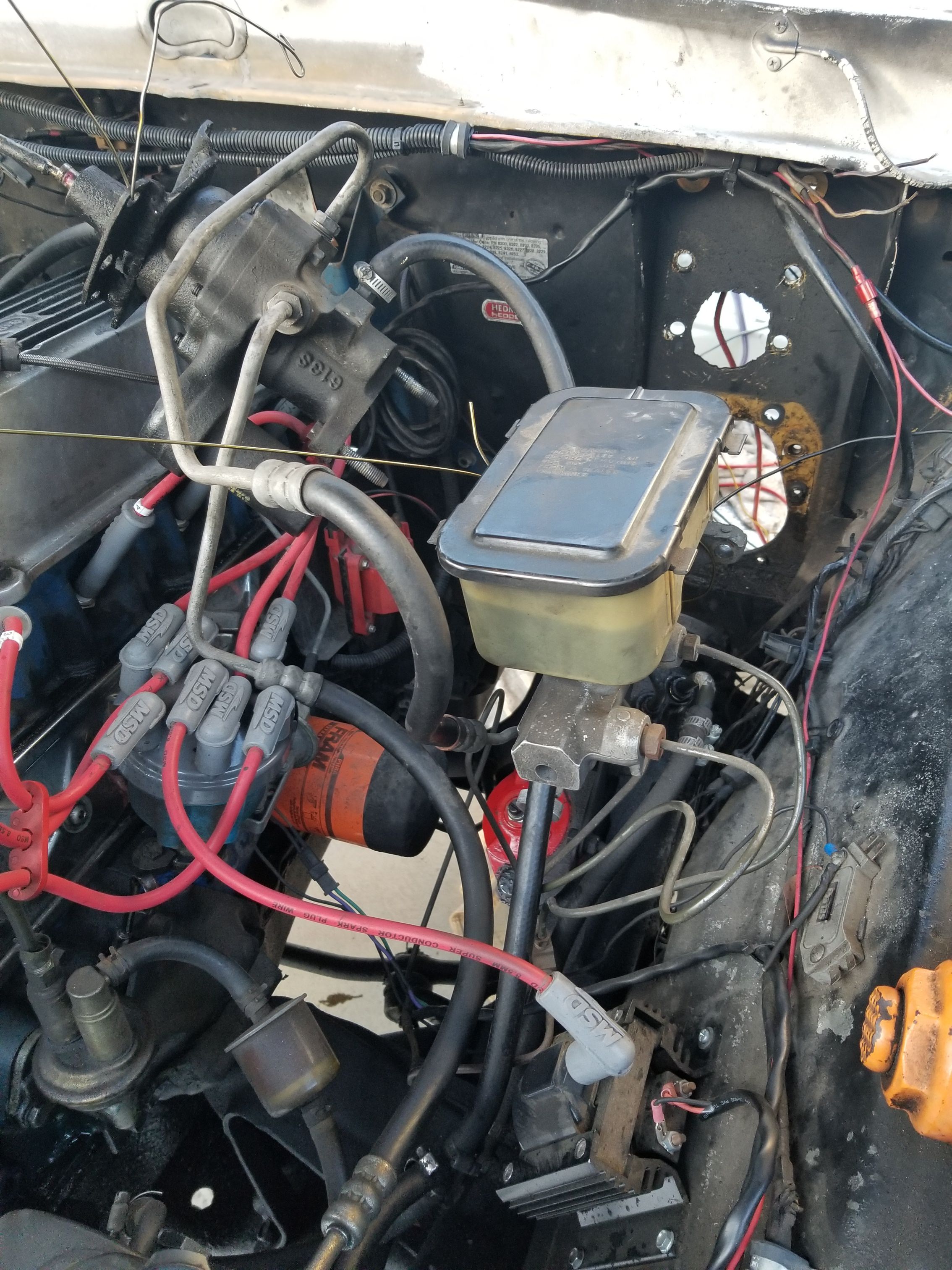
There is the HB unit and master. Both are about to be changed.
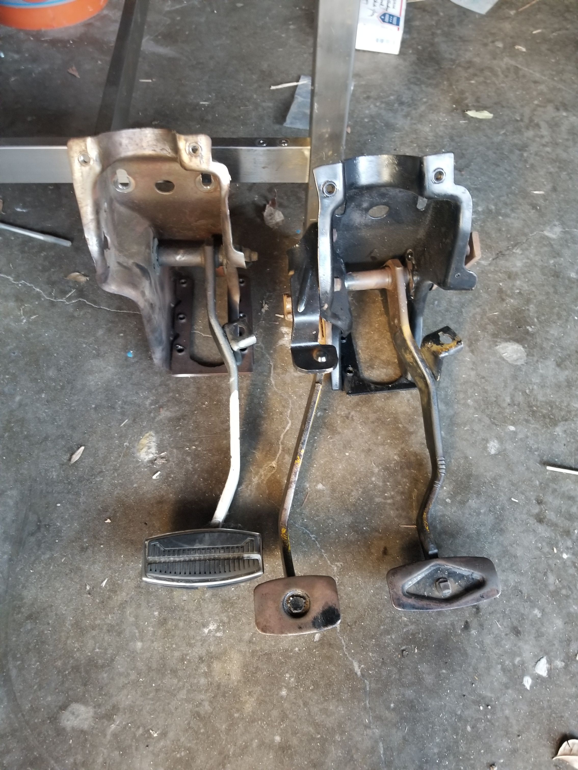
You can see the auto pedal assembly beside the manual unit that I added bearings to. Now I have to add the clutch master brace to the bracket. Some guys simply add a piece of sheet metal to their firewall to cope with the flexing caused by the hydro clutch master. I opted to attach the brace to my pedal bracket as you can see below. Today I will be fabricating the bracket and welding it together. I have read that people can see on the firewall divots created in the factory as a guide to show where the clutch master goes on the firewall. Mine, however, does not have those marks, so, I have to come straight across from the brake plunger, in alignment with the clutch pedal connection. Fun.
Attachment 278266
The plug from the column into the electrical is a bear to separate, and I broke it. LMC, here I come. I'll be sure to use some electrical grease before I put it back together.
I also found that my hydroboost unit was leaking, so I pulled it. It lasted 8 years. I used a hydro from a 94 Astro Van, and have decided to step up to one from a 99 F250 Super Duty with 7.3 Turbo Diesel. That will give me the Ford attachment. I'll only have to move the attachment bracket a bit from the firewall, to get the 5.65" oem length of the rod, so the pedal maintains its oem position. I'm going with the master for that model. With hydroboost, it is important that the master and the hydro mate correctly, or you might end up placing a rod in between to take up the slack, and with braking, I want to be confident every time I hit the pedal that all is well.
*Another point I'll make about hydroboost: It is very important that you have dual return lines, with dual returns into the pump, or you hinder flow and that will affect steering. You'll feel it in parking lots when on the brake and cranking the wheel. It will feel as though your p/s cuts out 75%. I got my Saginaw pump off a 78 LTD with a 460. The brackets can be taken off Econoline vans with your engine.
There is the HB unit and master. Both are about to be changed.
You can see the auto pedal assembly beside the manual unit that I added bearings to. Now I have to add the clutch master brace to the bracket. Some guys simply add a piece of sheet metal to their firewall to cope with the flexing caused by the hydro clutch master. I opted to attach the brace to my pedal bracket as you can see below. Today I will be fabricating the bracket and welding it together. I have read that people can see on the firewall divots created in the factory as a guide to show where the clutch master goes on the firewall. Mine, however, does not have those marks, so, I have to come straight across from the brake plunger, in alignment with the clutch pedal connection. Fun.
Attachment 278266