


1982 Ford e150 HEI swap wiring question

Thread Starter
|
New User
Joined: Mar 2017
Posts: 22
Likes: 0
1982 Ford e150 HEI swap wiring question
Hello, my 82 Ford econoline camper van has a 302 5.0 I just finished rebuilding top end.. wiring issues with distributor made me decide to just purchase an HEI from summit racing. They said all I need is to find a 12v turn key power source, does anyone know if I tapped into the accy terminal on the fuse box under the dash if that would work?? (See pic). I also have the I terminal on the solenoid, but I've heard not to do that, but same say it's ok. Any thoughts out there?
Thread Starter
|
New User
Joined: Mar 2017
Posts: 22
Likes: 0
Tap into the accy with a 12gauge wire with an inline fuse
And plug into Bat+ on cap of HEI... that it? Then I can discard
Ballast resistor, old coil, and then the I terminal on my solenoid wouldn't
Be hooked up? I just don't wanna F anything up
And plug into Bat+ on cap of HEI... that it? Then I can discard
Ballast resistor, old coil, and then the I terminal on my solenoid wouldn't
Be hooked up? I just don't wanna F anything up
Tuned

Joined: Mar 2010
Posts: 425
Likes: 1
From: Fayetteville, TN
You need 12v when the key is in the run and start positions. Accessory voltage typically doesn't have power when in the start position. I'm not familiar with an 82 so just make sure you have power in both positions and your good to go.
Logistics Pro


Joined: Oct 2014
Posts: 3,677
Likes: 172
You could use part of the existing DSll wiring supply if you add a normally open/normally closed 5 pin relay.
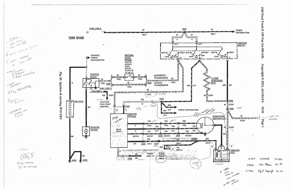
You should have a 2 plug socket with a white and a red with blue stripe that connects to the Duraspark ignition control module. The white wire coming from the ignition switch has constant power when the ignition switch is in the run position. The red with blue stripe has power only when the ignition switch is in the start position.
That plug is already in the general area..
relay wiring.
Terminal 30 - Common- will feed the HEI module.
Terminal 85 will be your ground.
Treminal 87a NC will be fed with the white wire that has power when in run.
Terminal 86 relay coil, and 87 NO, will be fed with the red/blue stripe wire. When the ignition switch is in the start position. You could mount the relay along with its ground screw right there on the fender well.
Now you have a single wire (common on the relay) that will have 12v on start and in run with no feed back issues.
The other connector that connects to the DSll ICM has wires in it that already run over to the distributor and coil so you shouldn't have to run any new wires to get over to the engine.


Thread Starter
|
New User
Joined: Mar 2017
Posts: 22
Likes: 0
Thanks Annaleigh, I'll look into that, I'm only concerned because that plug was never plugged in, the module had 2 plugs coming off it and only 1 was being used, I think you were right in previous post that a PO switched ignition systems, I got a test light today so I'm gonna dig some. Just so I'm clear run on the key is 1 click and start is 2 clicks and a full turn is cranking, but I'm not cranking yet cause I don't have the HEI yet, it'll be here Friday. Thanks so much for the help everyone
Thread Starter
|
New User
Joined: Mar 2017
Posts: 22
Likes: 0
Trending Topics
Thread Starter
|
New User
Joined: Mar 2017
Posts: 22
Likes: 0
Also I just saw if I only use those two wires, the I terminal from the solenoid wont be hooked up cause that wire was hooked up to the 12v constant white wire, so now where does the I terminal from the solenoid hook up?
FTE Stories
Ford Trucks for Ford Truck Enthusiasts

10 Fords to Drive Before You Die
Joe Kucinski
3 Best / Worst Features Of The 2025+ Ford Expedition
Brett Foote
10 Ways Ford is LOSING to the Competition
Joe Kucinski
Top 6 Best Deals Available on New Fords & Lincolns Right Now
Brett Foote
This Hennessey Takes the Expedition Tremor's Off-Roading Capability to the Next Level
Verdad Gallardo
Top 10 Fords at 2026 Carlisle Ford Nationals
Joe Kucinski
3 Best / 3 Worst Parts of Modern Ford Ownership
Brett Foote
10 Amazing Upgrades That Solve Common Ford Truck Owner Headaches
Pouria Savadkouei
Every 2026 Ford Engine Explained
Brett Foote
Thread Starter
|
New User
Joined: Mar 2017
Posts: 22
Likes: 0
Sorry for the posts, I hope I'm not confusing you. (See pics) This was how it was wired up, the bottom white wire which we found has a constant 12v hooked up to the bottom of the ballast resistor, then the top white wire ran all the way to the solenoid and in the middle of it was spliced and ran to the + terminal of the coil cap. Soooo if I take that 12v constant white wire and run it all the way to the solenoid and in the middle splice it and connect it to the the bat+ of HEI, would that make sense? I still not sure what to do with red blue stripe wire. Thanks for baring with me, I'm not the greatest with wiring
Tuned
Joined: Mar 2010
Posts: 425
Likes: 1
From: Fayetteville, TN
The I terminal should only have power when in the start position. However, your white wire will have power because it is spliced into another wire that most likely provides power when in the run position.
This is how it's supposed to work on the stock system. When the key is turned to START, power goes to the S terminal to energize the solenoid and power passes through to the I terminal to give the coil full 12+v at start. Once the engine is started and the key is returned to the RUN position, power is ran through a resistor wire or ballast resistor to limit the voltage to the coil to 8 volts, if I recall.
This is how it's supposed to work on the stock system. When the key is turned to START, power goes to the S terminal to energize the solenoid and power passes through to the I terminal to give the coil full 12+v at start. Once the engine is started and the key is returned to the RUN position, power is ran through a resistor wire or ballast resistor to limit the voltage to the coil to 8 volts, if I recall.
Logistics Pro
Joined: Oct 2014
Posts: 3,677
Likes: 172
On my key switch, turning it counter clockwise will put it in acc mode for the radio and all. turning clockwise to the first click should be the run position. from there, the second is the spring loaded start /crank position. Yours should be the same.
NO you cant just connect those two wires (white and red/blue stripe) to the HEI. If you just connect the two wires together at the HEI, when the ignition switch is in the run position, power will backfeed from the white wire through the red/blue stripe wire, to the ignition switch, neutral safety switch and then the starter solenoid keeping it engaged. That is why you need the relay so it will open the circuit on the red/blue stripe wire and stop the backfeed to the solenoid during the run position.
YES, you will not need it. It runs the stock ignition the van came with from Ford.
You have allot of wiring problems and hooking up the solenoid will be a separate part of this. The starter solenoid should be a red/blue stripe wire. IT is the same circuit as the red/blue stripe going to the 2 wire connector for the ignition control module.
Looking at your last set of pictures: At the top of the first picture, in the middle is the plug with the red and white wire you will be connecting to the relay. Does that red wire on that connector have a blue stripe?
The second pic with the ballast resistor, that is not the stock ballast resistor. The stock resistor is built into the wiring harness.
The third pic, that white wire was added to the solenoid and is not part of the stock wiring harness.
The forth pic, all those extra wires on the battery terminal probably need to come off as I imagine they are not fused... What do they go to? My van is a conversion van and has 2 fused wires from the positive terminal going to the inside accessories..
This is going to be hard to do over the internet.. I think what you need to do first before cutting or changing any wires is to trace out the original factory wiring and see what is there and usable.
You have other parts that are going to need to be working and are part of the harness going to the engine that was connected to the harness going to the engine and ignition. .. oil pressure sending unit, tempature sending unit, carburetor choke heater, ect.. The starter solenoid is a separate harness that runs across the top of the firewall in that plastic cable holder.
Who ever did the wiring before must have gotten lost and just started connecting wires to make it run.. or try to..
Can you take a pic of the inside of the distrubitor so I can see what type of pickup is in there
Logistics Pro
Joined: Oct 2014
Posts: 3,677
Likes: 172
It looks like the red/blue stripe wire is still connected to the starter solenoid on the solenoid S terminal, where does that wire go from there?
EagleFreek is correct that the coil needs full 12 volts during start and then after the engine is started, the coil is fed from the ballast resistor. If the round coil has full 12 volts all the time, it will overheat and burn up.
EagleFreek is correct that the coil needs full 12 volts during start and then after the engine is started, the coil is fed from the ballast resistor. If the round coil has full 12 volts all the time, it will overheat and burn up.
Thread Starter
|
New User
Joined: Mar 2017
Posts: 22
Likes: 0
I'll look at stock distributor in the morning, the pic were I'm holding the 2 wires in my fingers, the white one is the one I had power to in run position, how can I find the wire that has power in the start position without cranking engine? I might have to take it in. Summit racing said all I needed was a wire with 12v in run and start position, seemed too good to be true but hooking up relays and junk sounds confusing 
Logistics Pro
Joined: Oct 2014
Posts: 3,677
Likes: 172
Because the wiring is so chopped up, if it were my van, the first thing I would do would be to see how much of the original wiring is still in tact and try to hook it back up the way it came from the factory. If you don’t then you will probably have continuing problems that will be hard to solve because no one will know how it is wired.
The pic below is all there is to the original Duraspark ignition harness going from the plugs at the firewall to the engine. Very simple and it covers the oil, temp, dist, and coil. Again the starter circuit is separate from the ignition. If you go with the HEI ignition, you are going to need the oil and temperature senders hooked back up and those wires are in the original ignition harness and connect to the harness plugs coming out of the firewall.

This pick here, ignore the top round connector that you can only see part of, it is part of the starting system and does not connect to the engine. The square and round connector you do clearly see, those come from the firewall and connect to the ignition harness seen in the top pic.

The relay is really simple. here is what it look like and is only 5 bucks..
The red and white that you would use for the relay are clearly shown in your top picture. They are the 2 wires connected to the female socket right by the steering gear box. That female socket with the red and white wire is supposed to feed “start” and “run “ power to the ignition box that is supposed to be mounted on the fender well. That white has power when the key is in the “run” position and the red has power only in the “start” position.
Here is how the relay would wire up.
Relay connectors
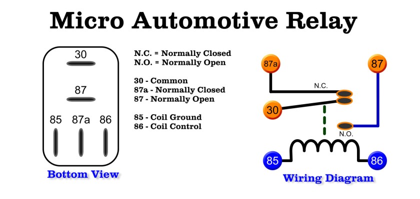
You will only be connecting 4 wires to the relay. A Ground, Red/Blue Stripe, White, and the Green (or what ever color you choose) wire to the HEI module. Red and White are there in that socket. The ground wire will screw to the fender well beside the socket and relay. You will run one wire to the HEI

Start/Crank circuit

The run circuit

The pic below is all there is to the original Duraspark ignition harness going from the plugs at the firewall to the engine. Very simple and it covers the oil, temp, dist, and coil. Again the starter circuit is separate from the ignition. If you go with the HEI ignition, you are going to need the oil and temperature senders hooked back up and those wires are in the original ignition harness and connect to the harness plugs coming out of the firewall.

This pick here, ignore the top round connector that you can only see part of, it is part of the starting system and does not connect to the engine. The square and round connector you do clearly see, those come from the firewall and connect to the ignition harness seen in the top pic.

The relay is really simple. here is what it look like and is only 5 bucks..
The red and white that you would use for the relay are clearly shown in your top picture. They are the 2 wires connected to the female socket right by the steering gear box. That female socket with the red and white wire is supposed to feed “start” and “run “ power to the ignition box that is supposed to be mounted on the fender well. That white has power when the key is in the “run” position and the red has power only in the “start” position.
Here is how the relay would wire up.
Relay connectors
You will only be connecting 4 wires to the relay. A Ground, Red/Blue Stripe, White, and the Green (or what ever color you choose) wire to the HEI module. Red and White are there in that socket. The ground wire will screw to the fender well beside the socket and relay. You will run one wire to the HEI

Start/Crank circuit

The run circuit
