Resistor Wire Bypass
#1
Resistor Wire Bypass
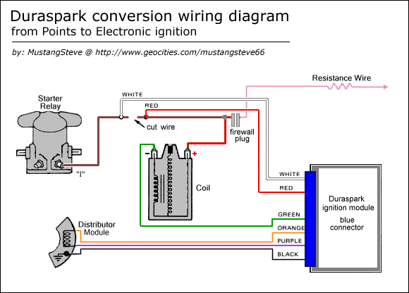
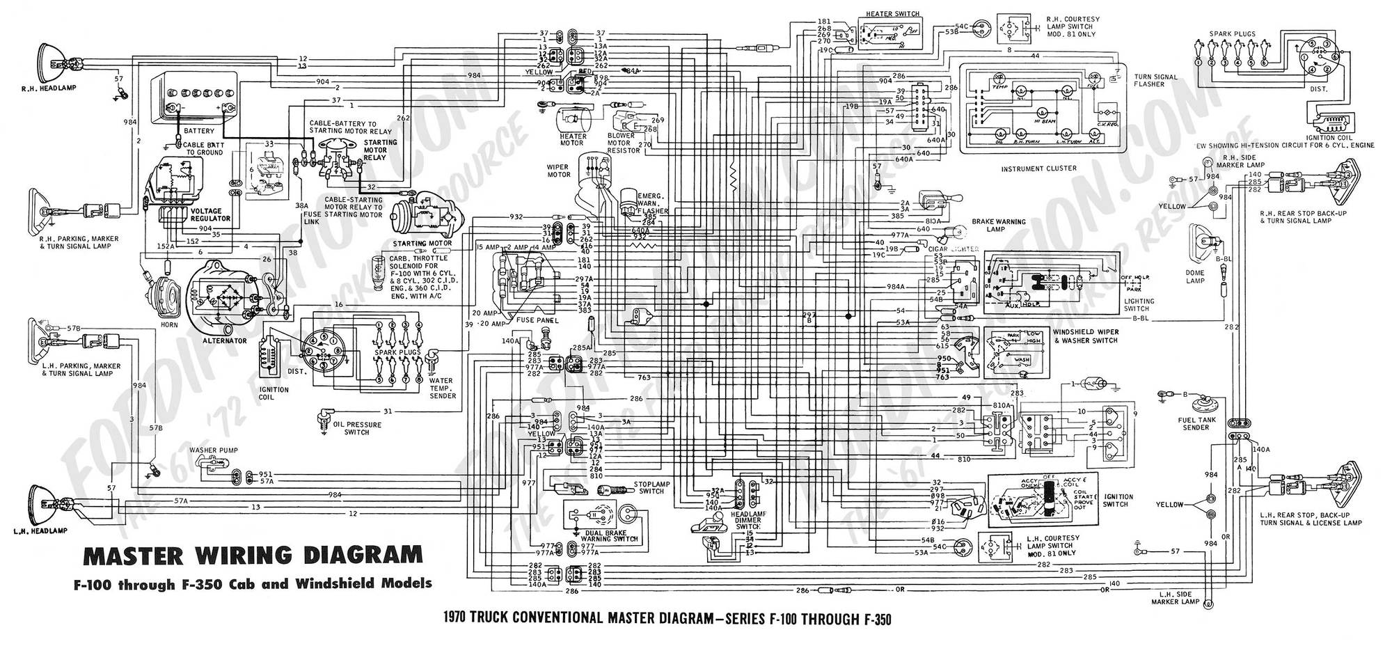
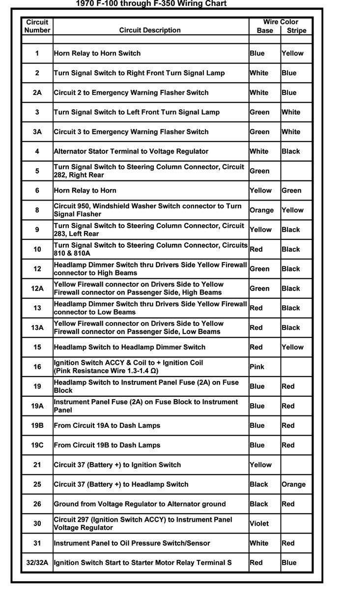
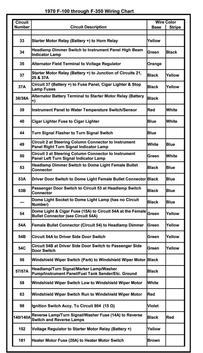
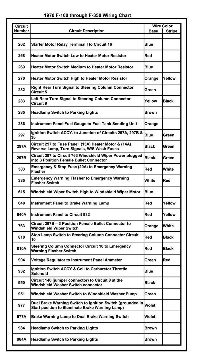
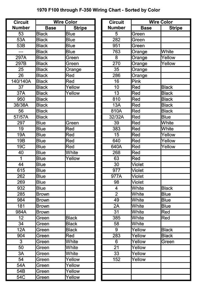
I am installing a new engine in my 1972 Ford F100 with MSD ignition which requires full 12 volts. I know there is a resistor wire under the dash and I have found it. It appears to go directly into the ignitor switch from the plug. I just can't figure out where it goes after that. The wiring on this thing was a mess from whoever added the Duraspark 2. I'm really not good with wiring yet and I know this has been discussed multiple times but I have some questions. Where does the pink wire go out of the plug? Was it supposed to go directly to the coil or does it turn into another color wire before going through the firewall? What can I do to ensure I have full 12V during cranking and running? Maybe there's another wire that comes off the harness that has that? I'm confused as to what all 6 terminals do on the switch. Sorry for all the questions. Like I said, I'm not good with wiring so I'm having a hard time with it. Any help is appreciated. Thanks.
#7
Trending Topics
#8
I just did this to install an HEI dist.
I pulled the plug off the ignition switch, cut the pink wire but left enough to graft to.
Soldered and shring wrapped that connection then went to the plug in the engine bay where that wire terminates with the start 12v. Cut it again leaving enough to connect, soldered and shrink wrapped.
Leaving small sections of the resistor wire does not affect the 12v you're looking for.
I now have full battery power at the coil in run mode.
#10
Join Date: Aug 2003
Location: **** hole San Jose ca.
Posts: 7,592
Likes: 0
Received 9 Likes
on
9 Posts
I just did this to install an HEI dist.
I pulled the plug off the ignition switch, cut the pink wire but left enough to graft to.
Soldered and shring wrapped that connection then went to the plug in the engine bay where that wire terminates with the start 12v. Cut it again leaving enough to connect, soldered and shrink wrapped.
Leaving small sections of the resistor wire does not affect the 12v you're looking for.
I now have full battery power at the coil in run mode.
I pulled the plug off the ignition switch, cut the pink wire but left enough to graft to.
Soldered and shring wrapped that connection then went to the plug in the engine bay where that wire terminates with the start 12v. Cut it again leaving enough to connect, soldered and shrink wrapped.
Leaving small sections of the resistor wire does not affect the 12v you're looking for.
I now have full battery power at the coil in run mode.
Bet, I could guess it's age.

Orich
#13
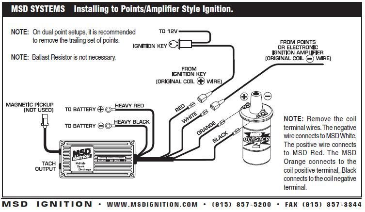
The way that others have showed is right. However, I used my resistor wire to plug into the MSD. Works fine. I visit the FE engine forum and was enlightened on this subject over there. All the small red wire does is turn the MSD on. The stock resistor wire will not drop the voltage enough to know. It is far more important that your big red wire has good 12v right from battery and that the big black wire has a good ground. I have been running mine with the resistor wire for all summer and no problems.
#14
So I have another question. I understand there is another brown wire that provided a full 12 volts while cranking only. Does the resistor wire not get anything while cranking? What I'm wondering is if I can just splice in a wire to the resistor wire (taking away the resistance) like someone above did and only use that wire? Or do I still have to run another wire to the coil to get power while cranking also?


