Looking for wiring diagram
#1
Looking for wiring diagram
Hi guys,
I just picked up a 03 Navigator for my wife. Nice car, just needs a couple of small things.
One thing that I'm having a problem with is the Drivers side heated seat. The switch also has AC in it. Neither heat or AC is turning on so I took it apart and did read 12 volts at the connector, I'm making the assumption that this is the power to the switch since I don't actually have a diagram.
The passenger side switch is working fine.
Anyways, assuming the switch wasn't working correctly I purchased a new one. Of course it didn't work.
So my question is one, does anyone have a diagram of the heated seat circuit? and two, is there an common issue with others and the heated seats?
Thanks guys
#2
#3
#4
Not really, the 30-amp circuit is the power for the seat pads while the 10-amp circuit is for the controls. But with either circuit they both go to both seats. So if one seat is working and the other is not, then the portion of the circuit that goes from the fuses to the first splice is good.
#5
#6
Well, per the diagram should have power at the switch location on both the blue and red wire to ground. None there, so that is leading me to the CCM. I'm trying test the wires there for power now.
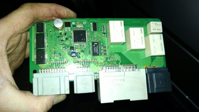
If I could figure out how to get those modules out of there I will swap them out to see if that's the problem. Google is not cooperating with me though...haha. I was hoping to find a video to show me how they come out. No luck
If I could figure out how to get those modules out of there I will swap them out to see if that's the problem. Google is not cooperating with me though...haha. I was hoping to find a video to show me how they come out. No luck
#7
Trending Topics
#8
#9
Alright, so I think I have actually found the CCM, very tight. I removed the 4 pin connector.
Red/Black strip and White/blue stripe should be my 12 volts
I assume the black/Green stripe is the ground
Using the DVM, I get 0 volts from power to ground, Hook ground to seat metal as well and got nothing. Fuses are good
Red/Black strip and White/blue stripe should be my 12 volts
I assume the black/Green stripe is the ground
Using the DVM, I get 0 volts from power to ground, Hook ground to seat metal as well and got nothing. Fuses are good
#10
Definetly need to walk away... Decided to take the connector off the passengers side off as well to compare the voltage. That is a working seat... same thing, 0 volts between Red and Ground and White and Ground. Checked DVM, even used another DVM, same readings.
Been on this all day and feel like I've made no progress...ugh!
Been on this all day and feel like I've made no progress...ugh!
#11
#12
That's right, However according to that print, if I have no power where I stated below, I wont have any power at the switch harness.
BTW.. I did try a brand new switch in the beginning and that didn't work either.
Alright, so I think I have actually found the CCM, very tight. I removed the 4 pin connector.
Red/Black strip and White/blue stripe should be my 12 volts
I assume the black/Green stripe is the ground
Using the DVM, I get 0 volts from power to ground, Hook ground to seat metal as well and got nothing. Fuses are good
Red/Black strip and White/blue stripe should be my 12 volts
I assume the black/Green stripe is the ground
Using the DVM, I get 0 volts from power to ground, Hook ground to seat metal as well and got nothing. Fuses are good
#13
From the RD/BK wire to the BK wire should be 12 volts all the time. From the WH/BL to the BK wire should be 12 volts only when the key is on.
#14
That's how I tested it, actually had the truck running. Whats strange is both seats had no voltage. Yet the passengers seat works. I tried 2 different DVM's and had the same reading. Doesn't make sense.
#15


