When you click on links to various merchants on this site and make a purchase, this can result in this site earning a commission. Affiliate programs and affiliations include, but are not limited to, the eBay Partner Network.
I know there are a couple of these threads out there, but thought instead of asking, I'd try to contribute a bit. I found the information in a couple of spots, and figured I'd consolidate it. My conversion was inspired by Killforfood on this thread. Made my life pretty easy. THANKS!
I inspected my set of Dorman Gasket sets. I really do believe in the quality of the Ford parts, but I picked my Dorman set up for under $150, compared to the $400 I was about to spend at Ford. At this time, that was money I just could not spend. Also reading around, it seems Dorman has updated their design to eliminate the connection on the inside of the valve cover. They are lifetime warrantied, so the only loss is labor, and with no connections on the inside, the plug should be easy enough to keep an eye on.
Everything needed, except heat shrink. Quality seems ok.
Wires could be a little heavier.
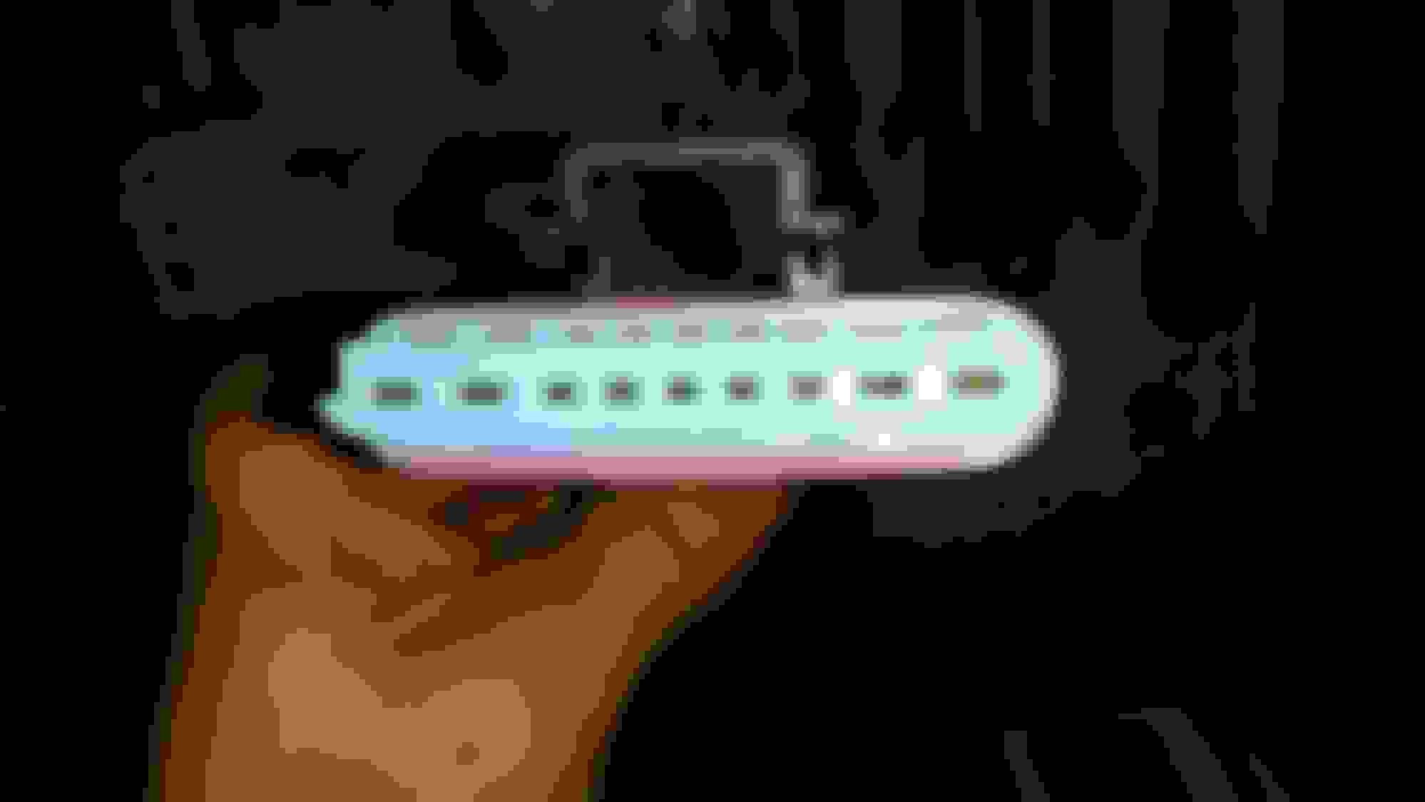
I test fit the connector to the gasket, and had fits getting it back off, on the bench with pliers and screw drivers. I don't see it coming loose at all.
Not gold plated contacts, but the glow plug pins are sufficient size.
I REALLY like that the connector is molded into the gasket. NO connector on the inside of the valve cover to come loose
I had 3 connectors melted on the outside, and at least 2 on the inside, and one missing the clip. I honestly don't see how the glow plugs were functioning at all
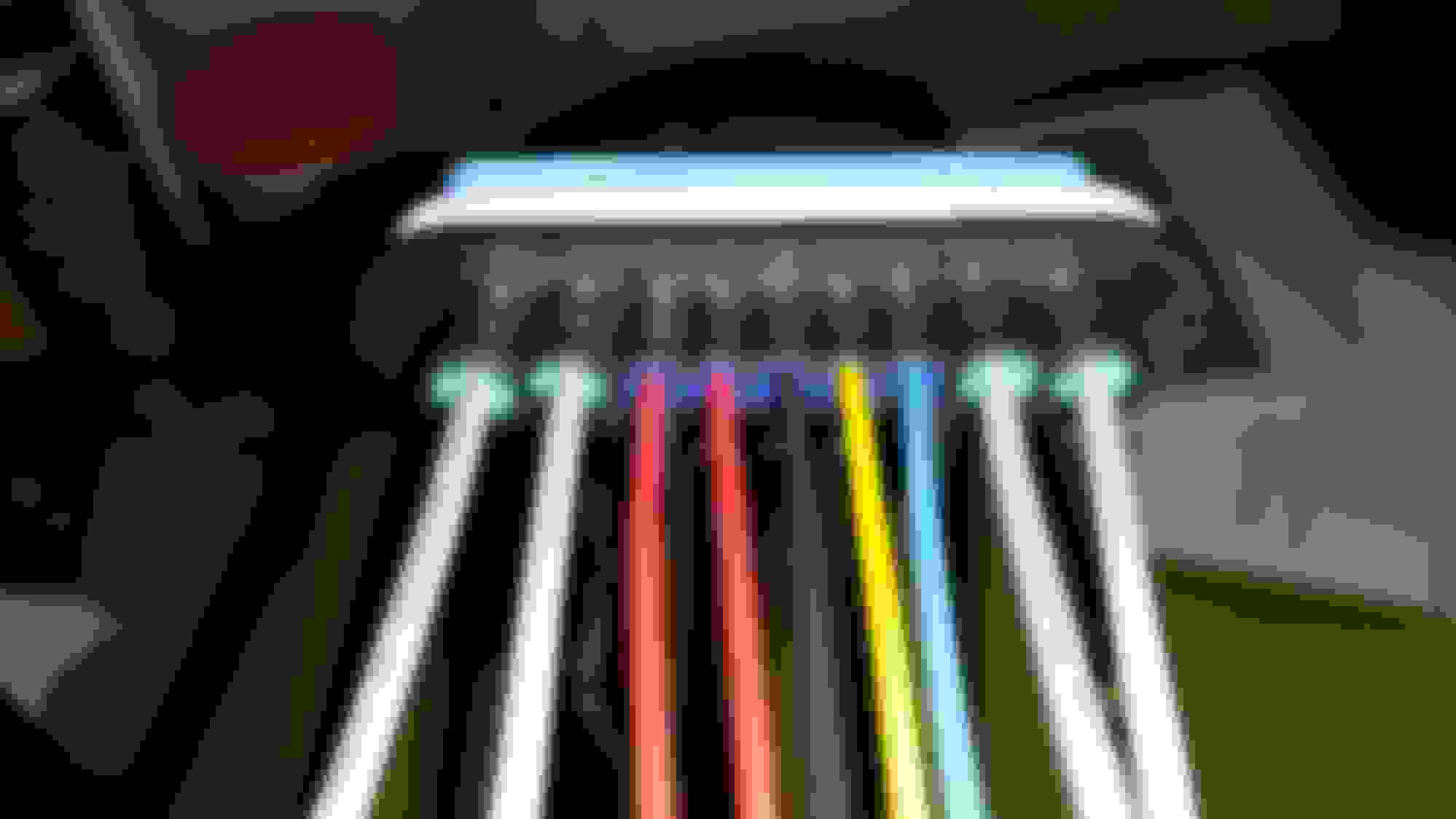
I used the wiring diagram that came with the gaskets, and two diagrams found on the thread that I linked, to associate the SD connector, my 42 pin numbers and colors to the cylinder numbers. I did this the night before I started, then rang everything out before I cut any connectors, and again, after soldering the new connectors.
Right side 1996 OEM to Dorman Colors
Left side 1996 OEM to Dorman Colors
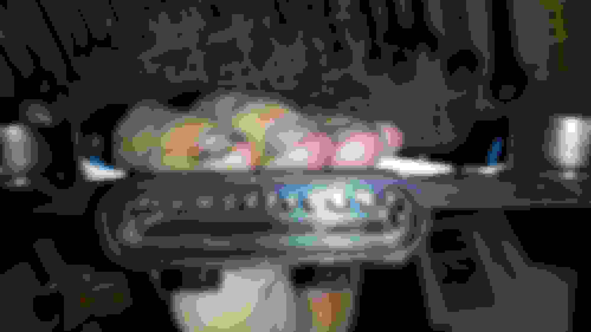
I soldered and put heat shrink on each of the connections
Then I put heat shrink over the whole injector bundle. Make sure to put your heat shrink on before soldering.
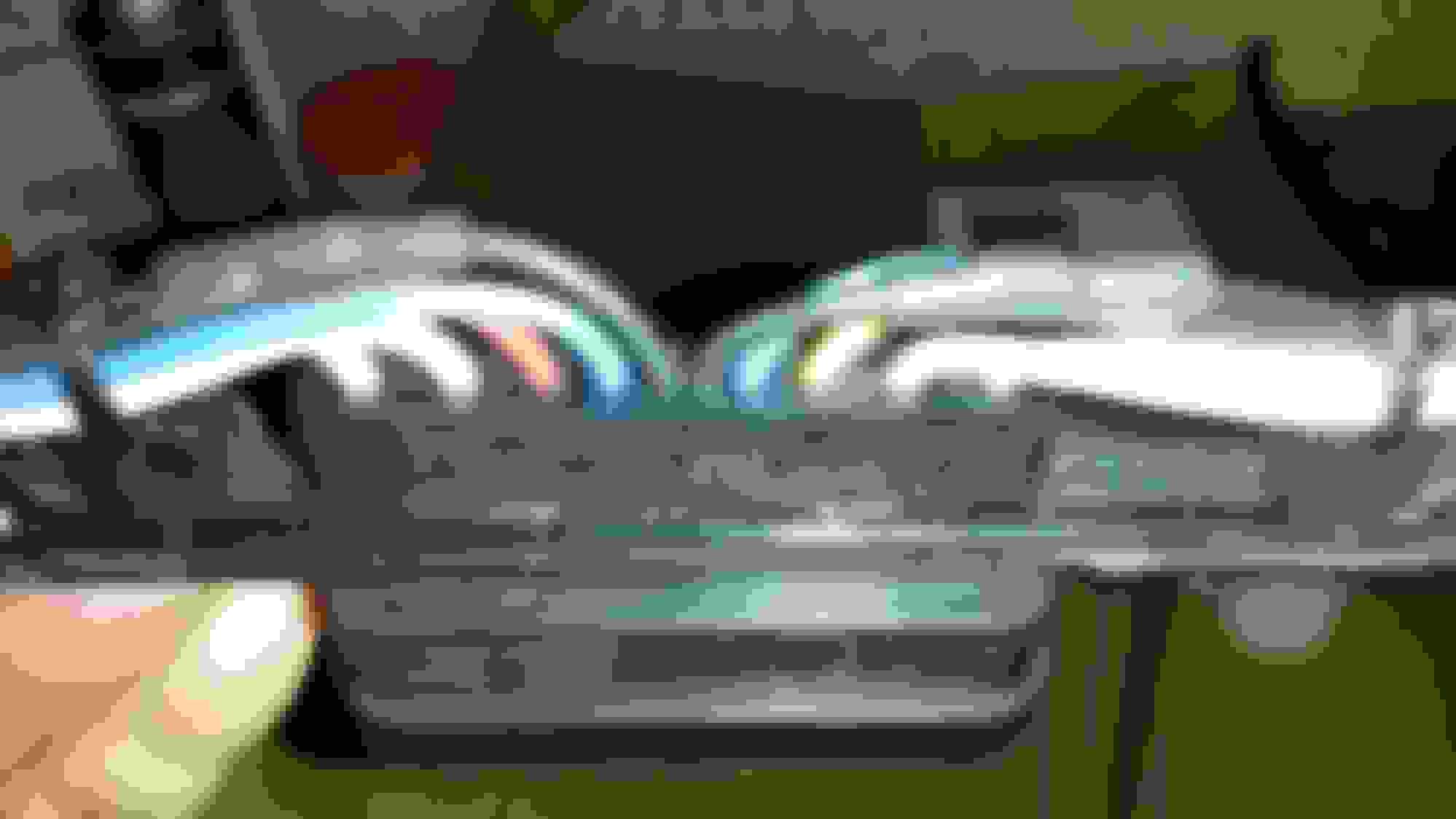
I wrapped the shield wire up to this heat shrink, then ran it though and wound the shield up the rest of the way. I used a clove hitch at the end to secure it.
I did the same thing with the foil, then used the heat shrink to secure it all in place
Finished assembly, ringing each wire from the 42 pin to the injector, and relay to each glow plug.
The pin numbers hidden by the wire in this pic, from top to bottom, are 10(INJ #8), 8(INJ #6), 6(INJ #4), and 3(INJ #2).
This is an SD pin out I found floating around. Note, on this one pin 16 is the left side HV. On another diagram I found, and on my OBS, the left side HV is pin 11.
The harness is still sitting on my bench, so hopefully I didn't get ahead of myself posting this..haha. My iron crapped out on me about 4 wires in, so I finished using a pencil torch with solder tip. OHH JOY.
I had a bad connection at the glow plug relay I had to fix (corrosion). The starts seem to be a little be longer than I remember too. Before the work I had an uneven idle at start, that persists, and it took 2-3 minutes of high idle before it evened out. But all in all it runs like it did, and no excessive heat on the connectors. I'm going to call it success.
I had a bad connection at the glow plug relay I had to fix (corrosion). The starts seem to be a little be longer than I remember too. Before the work I had an uneven idle at start, that persists, and it took 2-3 minutes of high idle before it evened out. But all in all it runs like it did, and no excessive heat on the connectors. I'm going to call it success.
Good job man this is starting to look atractive, I have a complete sd harness that I might use, from the looks of it I just need to splice some of the sensors wires
Thanks guys. Replaced the radiator last night and this morning sprung a leak on one of the metal cooling lines for the trans. Got the open element filter installed, and the down pipe, but the pipe is against the cab. Wow that's loud, so gotta pull the DP and make some room. I'll follow up with those in another thread maybe.
So I am starting on this project. I am looking for this diagram, can anyone direct me to a full page? Also, a PIN diagram for the harness connector..? Thanks
The pin numbers hidden by the wire in this pic, from top to bottom, are 10(INJ #8), 8(INJ #6), 6(INJ #4), and 3(INJ #2).
welp I found this one. I have a 94.5 7.3 My High voltage wire is crossed. So on the PIN Injector 2, 4, 6, 8 are connected to the PIN #12. Oposite of what all my diagrams I have found. Is this just a constant current wire??? or ground? It says High Voltage, but what is it??? Constant? for what?
I remeber finding this 2000 excursion print, and I remember there being a difference. I am offshore and do not have access to all my information, but this may help. https://www.ford-trucks.com/forums/1...o-links-4.html Page 4 post 52.
This Hennessey Takes the Expedition Tremor's Off-Roading Capability to the Next Level
Slideshow: The VelociRaptor Expedition gains a lift, upgraded suspension, Brembo brakes, and trail-ready equipment while retaining the stock 440-horsepower EcoBoost V6.
Rezvani's Latest Post-Apocalyptic Monster Is a Ford F-150 Raptor Underneath
Slideshow: Called the Fortress, the 850-horsepower pickup combines Raptor underpinnings with military-inspired features, survival equipment, and a starting price of $285,000.


 .
.