When you click on links to various merchants on this site and make a purchase, this can result in this site earning a commission. Affiliate programs and affiliations include, but are not limited to, the eBay Partner Network.
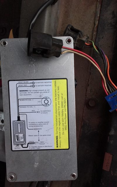
The igntion module died and am repacing it with an MSD 6A. If you click the picture it gets huge. The 5th wire down on the instructions on the back of the MSD 6A is red and it says to connect it "to switched 12 volts."
Does that mean the it connects to the ignition switch? The next one down says to connect it "to points or amplifier output (connects to yellow wire of timing accessories)." I have no idea what that could mean.
I cut the wires from the ignition module and I would like to use the OEM connector to the ignition switch. I think if I splice the "to switched 12 volts" wire to the red wire of that OEM connector that might work. Is that correct? Meanwhile, one set of instructions I downloaded says the white wire on the MSD 6A is not used. Do I gnore that and send this wire need to the accesssories switch on the ignition? Should it be connected to that white wire?
Also, from the wiring diagram I saw here, that red wire out of the ignition module shoud be red/blue, I think. Am I missing something?
Colors varied a bit by year ... wouldn't worry about the lack of a blue tracer, but yeah the red wire on the original DuraSpark ICM is what you'd want for the switched 12V. The orange and purple wires are the ones that go to the pickup in the distributor: looks like that would be green & purple on your new module. You're using that and don't have points, so you'd ignore the white wire on the new module.
I'm a little confused on which wire goes to the distributor, but I have taken a shower for the night and I will look at it tomorrow with your post in hand so maybe it will make more sense.
There's a 3-wire connector coming off the distributor: it has black (ground), purple, and orange wires. The purple and orange wires are the magnetic pickup - look at the bottom of the wiring diagram on your new ICM.
If you're having this much trouble with it, why didn't you just get a new Motorcraft DuraSpark module? Would've been plug and play without having to re-wire anything, and the Motorcraft brand modules are very reliable. Anyhow, I'm sure we'll get you sorted out on this one.
Cool. Not sure you'll see much difference unless you're running lean or boosting or doing something else where the OEM spark would be too weak, but it should be a good reliable module and leave you well-positioned for whatever future upgrades you may have planned.
8 on the msd box violet wire is + and on the ford harness the orange wire is positive coming from the dizzy. If you pull up MSD's install instructions page 18 has a diagram.
That red wire (with the supposed blue tracer that's missing) supply voltage when the ignition switch is in the start position?
According to the '79 schematics I have, it shows that it only supplies power when the ignition is in the run position and not start. Maybe stuff a voltmeter on the wires to confirm power during start?
I ran into this problem when I used wire 32(Red/Blue) and 732(White) to power on my EFI. I eventually used some diodes to a relay which powers the EFI. Maybe you could use some diodes to directly power the MSD box?
Hadn't thought of that ... Zark-eh is right about the likely need for diodes. The red wire would have ~7-9 V on it during cranking, backfed through the resistor wire via the "I" wire powering the coil, but that may not be enough; if there are problems during cranking, additional work would be needed to bring it up to 12V using a diode-isolated circuit.
Know those 5 spade 30-ish AMP relays? The kind people use for everything, like headlight relay kits and off-road lights and stuff...
They are labeled 85, 86 solenoid windings, and 30, 87a, and 87 for the Switch.
Spade 86 is wired negative, or Ground. Spade 85 is positive and in this application (MSD Box) the Diodes will attach here and from those diodes, will go to those two wires I described above.
Spade 30 goes to a Fused Power feed, and Spade 87 Goes to the MSD Box.
Diodes allow electrical current flow in only one direction, and have a band that indicates which end is which. In This Circuit, the Band goes towards the relay, and the other goes to that Ford Ignition Module wires, One Diode for each wire. The Band side of both diodes are then attached and wired to the relay spade 85.
A 1N4007 Diode should do, and are what I used for this and for cutting out flyback currents from relays. I'll try and draw something to make this easy to see...
Rezvani's Latest Post-Apocalyptic Monster Is a Ford F-150 Raptor Underneath
Slideshow: Called the Fortress, the 850-horsepower pickup combines Raptor underpinnings with military-inspired features, survival equipment, and a starting price of $285,000.


 Would've been plug and play without having to re-wire anything, and the Motorcraft brand modules are very reliable. Anyhow, I'm sure we'll get you sorted out on this one.


