When you click on links to various merchants on this site and make a purchase, this can result in this site earning a commission. Affiliate programs and affiliations include, but are not limited to, the eBay Partner Network.
Forgive my ignorance if this sounds stupid but wouldnt moving the cross member forward effect the positioning of the engine mounts and engine? or do you plan on taking the engine mounts straight from the frame?
I have no experience in this but am trying to pick up a few things before starting a project of my own.
I just received the identical front end as yours from TCI. They had to notch the back side of the cross member in order for the coyote motor to fit. Yours doesn't look notched but maybe its because you are pulling it so far forward.
nicholas,
Might I suggest you go into the control panel (click user cp left end of the blue band at the top of the page) and add your location, create a siggy with your year and model truck in it (plus any other info and a picture if you'd like) that will appear at the end of each of your posts, and also turn on receive private messages and email.
Once done, your location will appear at the top right of each of your posts, and the truck info will be at the bottom. Turning on PM and Email will allow other members to contact you privately and/or offline. To send another member a PM or Email left click their user name in any of their posts and select send PM or send email from the drop down menu.
I am installing my TCi front end and the instructions say to put the thread end of the shocks toward the bottom but it isn't fitting in the lower control arm, are those shocks ok to run inverted like you are showing? Maybe those instruction were written while they were using another type of shock.
Originally Posted by Nicholas+
Thanks for the welcome. The Aluminator should be a fun motor and make for a challenging build. Building 'em is most of the fun anyhow? The Aluminator is an upgrage from the basic modern 5.0 Coyote found in the '11-15 Mustangs. The Aluminator has all forged internals, Mahle forged pistons, Manley H beam forged rods and ARP bolts. It good for 1000 HP. All those forged internals bump up the RPM redline to 8000+RPM. Should be a fun ride. But I'm not even close to all that....
Ive been working on the plan for about a month now and making sure the budget matched the ambition. Working on the chassis now. I have a TCI Custom IFS. It seems like a real nice set up. I like how it is a one piece unit and just drops in. It actually created an idea and changed the plan a bit.
Because the TCI unit drops in and rests on the frame rails it got me sliding it all around. After some thought I decided I want to move the axle center line considerably forward. I'm moving the wheel arches 3 3/4" forward and moving the axle C-line to match.
A little mock up. This is what I was going to go with... "Centered to my taste".
Then some thinking over frosties...
I think this will really impact the look favorably IMO. Got my new fenders mocked up and ready to cut. I'll post some pics of the completed augmentation in a few days if all goes well .
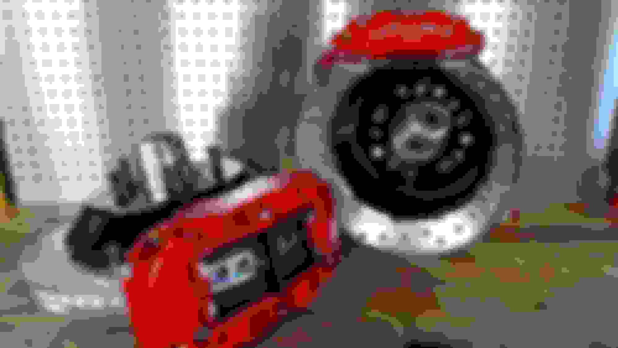
It's gotta stop too right? 13" Wildwood rotors and 6 piston pots will be up front.
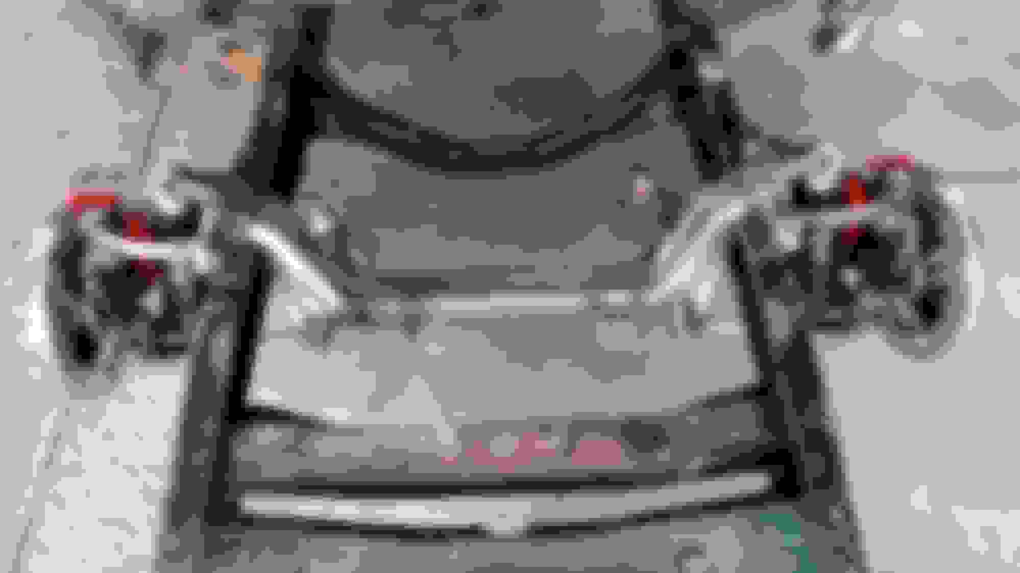
Also went with upgraded Ride Tech Coil overs. Here how the sweet TCI Custom looks set on the frame rails...
also, not to hijack but the TCI instuctions say that the axle center is 21'' from center of front shackle hole but I found some older TCI instructions online and they said 20.5" I thought it would just be to measure my bump stop hole which is also 20.5'' but i read somewhere that those weren't exactly centered because the arc of travel on the original suspension. 1/2'' doesn't sound like much but i want to make sure i get those wheels centered, anybody know?
also, not to hijack but the TCI instuctions say that the axle center is 21'' from center of front shackle hole but I found some older TCI instructions online and they said 20.5" I thought it would just be to measure my bump stop hole which is also 20.5'' but i read somewhere that those weren't exactly centered because the arc of travel on the original suspension. 1/2'' doesn't sound like much but i want to make sure i get those wheels centered, anybody know?
Hey bud. The shocks are okay to run either way. They are nitrogen filled. You can contact Ride tech and get it direct from them as well.
As for the wheel centering...I take it you don't have the cab on? I played around endlessly finding the perfect "centered look". The measurement TCI gives puts it in the factory location and your actual wheel centerline will be right around the bump stop hole. On the TCI unit (at least mine) the centerline of the wheel is not the centerline of the cross member. So keep that in mind. I took the measurement off different locations for ease.
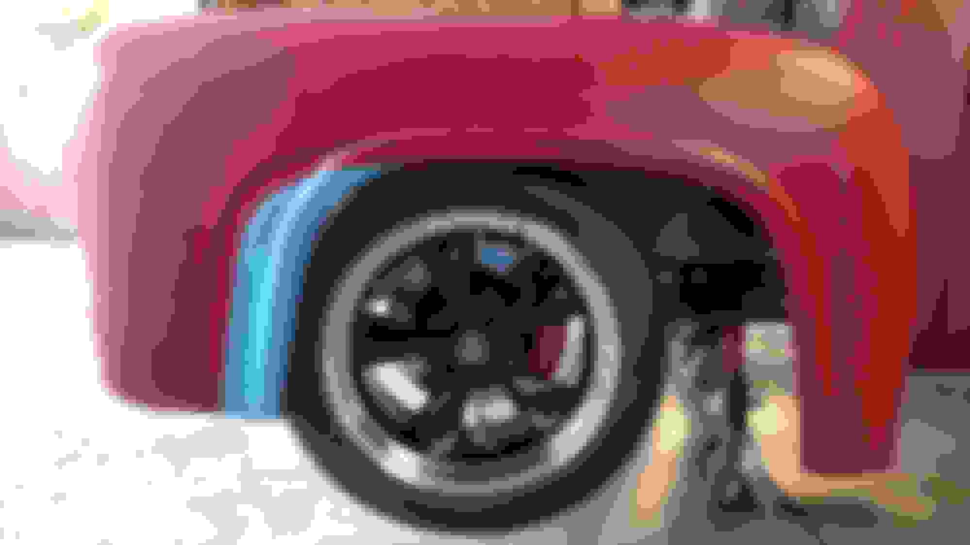
On top of the frame there are three rivets just above the old front spring riviet triangle. I measured from the center of the center rivet on top of the frame rail to the front edge of the cross member and had 20 5/8". That is what I was going to go with until I decided move it farther. I'd check for your self thought. Feel free to PM me with any questions.
In the picture you will see a few things. Notice the three rivets I was talking about. Also the silver line on the side of the frame rail is where I marked the existing centerline of the axle before I removed it. The silver line on top of the frame just behind the blue tape by the 20 5/8" mark is where the front edge of the TCI cross member would sit if I were going for centered. The blue tape is where my cross member will sit.
I'll have some updates up soon. Almost done with the fenders. Spent a while trenching to run a new 50 amp service to the garage. Bought a bigger welder and didn't have 240 in the garage.
thanks, for the info. i just went out and measured where i had the crossmember centered and it was exactly 20-5/8'' like you r measurement. Guess ill go with that.
keep us updated, I like your build.
did you mount your rack and pinion yet? TCI sent me 5'' rack, i put it on and it is a couple inches closer to the passenger side than the drivers side when I have the steering centered. The drivers rod end isn't long enough to bolt to the spindle with the wheel pointed straight down the road, just wondering what the best solution is.
Nah. Haven't got to that yet. Still working on the fenders. Holy crap is it a lot of work. Getting there though. I don't know what you mean by 5" rack? Did you do like it mentions in the instructions?
If you did that and still have an issue just give em a call. They seem like cool dudes. I talked to the guy for a while about the difference between tru track lockers and friction type. Seemed very willing to help and knowledgeable. I also called to ask if the uppers control arms were the same left and right just to be sure. They are, and again they were cool to answer.
when you bolt up the rack and pinion, you will see that the cross member mounts locate the rack about 2'' closer to the passenger side for some reason. When i told them I wanted to do a coyote they said my cross member had to be notched and my sway bar had to move to the front instead of the rear so it wouldn't hit the oil pan. Their standard kit comes with a 6'' rack and pinion but they said it would hit the front mounted sway bar so the 5'' is the one they sent. because the cross member isn't centered, the one rod end fits easy, the other barely catches 2 threads and thats with the spindle tweaked in a little. I will call them tomorrow, they are pretty cool guys.
The wheel arches are in. Now i need to make patch panels to fill in the void left from moving them forward. Here are some pics making the filler piece.
I cleaned up the fenders good with some acetone so the tape would stick well. Then tape on a piece of drawing paper. I took my time and taped it up so it was nice and taunt like a drum skin.
I use a pencil lead from one of those retractable construction pencils. I rub it on tracing the outline. This system works good for lots of different things..
Then I like to put a backer on the fragile paper and use some more blue painters tape. I cover the entire backside with it, then flip it over and cut it out with a fresh and xacto place.
Now I have a solid template.
I trace it out with a fresh xacto blade and cut it out with a 4" wheel. Here's my patch panel. Repeat for the other side.
Here's a suggestion: If you read thru my F1 fender rust repair tutorial https://www.ford-trucks.com/forums/1...g-try-2-a.html you'll see pix on how I make my patterns using inexpensive lightweight posterboard from the school supply section at most big box and grocery stores, and hold it in place while tracing etc with 1/2" diameter x 1/8" rare earth magnets. I bought my magnets in a pack of 6 at my local northern tool store for a couple bucks. Also available from Harbor freight and on ebay. They are very strong, not only to hold the board, but even strong enough to hold the sheet metal in place. I like the poster board because it is durable enough to withstand handling and multiple uses but light enough to easily cut with scissors or knife. It can also be folded and curved. If the posterboard won't lay flat, then neither will the sheetmetal, the area is likely a compound curve that will need to be dealt with. Are you Mig or Tig welding?
Rezvani's Latest Post-Apocalytic Monster Is a Ford F-150 Raptor Underneath
Slideshow: Called the Fortress, the 850-horsepower pickup combines Raptor underpinnings with military-inspired features, survival equipment, and a starting price of $285,000.


 .
.