


missing hose?
Thread Starter
|
Cross-Country
Joined: Aug 2006
Posts: 85
Likes: 0
missing hose?
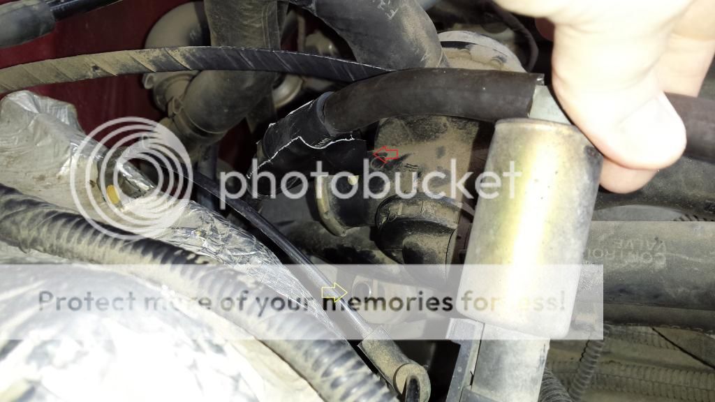
Hi was was hoping someone can help me out, I was hearing a sucking noise coming from the engine of my 1996 ford f250 7.5 V8 460 truck and i finally found out that it was coming from the pcv valve hose and a guy from Napa told me to just tape the end up because it was just a "t" connector that carries away fumes from the oil. so i taped it up and after taping it the noise was gone but i did notice a port on the engine that has nothing going to it so i was wondering is a hose from the pcv "T" suppose to go to the port on the engine the yellow arrow on the pic is the port and the red arrow is the "T" that's taped. is that right?

Thread Starter
|
Cross-Country
Joined: Aug 2006
Posts: 85
Likes: 0
Thanks a lot of the replies, SO the open port on the engine is the smog pump and that's suppose to be open like that right? Do you know anything about the pcv "t" Ive tried looking online and even had oreillys and Napa look and they cant seem to find anything that will work. so for now its just taped to stop the sucking. Thanks again I just want to make sure i understand it.
Fleet Owner


Joined: Oct 2005
Posts: 20,789
Likes: 1,753
From: Kentucky
The photo above is not showing the PCV valve, that is the Canister Purge Valve (CANP).
One end goes to the intake manifold near the throttle body, perhaps on the throttle body I do not recall. And the other end goes to the charcoal canister. It's part of the evaporative emission system. The fuel tank vents to this canister most of the time. The computer commands the valve to open so the stored vapors are pulled into the engine.
One end goes to the intake manifold near the throttle body, perhaps on the throttle body I do not recall. And the other end goes to the charcoal canister. It's part of the evaporative emission system. The fuel tank vents to this canister most of the time. The computer commands the valve to open so the stored vapors are pulled into the engine.
Fleet Owner
Joined: Oct 2005
Posts: 20,789
Likes: 1,753
From: Kentucky
Someone is feeding you false information.
Trending Topics
Thread Starter
|
Cross-Country
Joined: Aug 2006
Posts: 85
Likes: 0
so everything in the picture looks normal and suppose to be that way? thanks again for the help.
FTE Stories
Ford Trucks for Ford Truck Enthusiasts

3 Best / 3 Worst Parts of Modern Ford Ownership
Brett Foote
10 Amazing Upgrades That Solve Common Ford Truck Owner Headaches
Pouria Savadkouei
Every 2026 Ford Engine Explained
Brett Foote
10 Ugly Ford Trucks That We Still Kinda Love
Joe Kucinski
10 Things Every Truck Owner NEEDS (2026 Edition)
Michael S. Palmer
Rezvani's Latest Post-Apocalyptic Monster Is a Ford F-150 Raptor Underneath
Verdad Gallardo
Top 10 Most Expensive Ford Trucks Ever Sold on Bring a Trailer
Joe Kucinski
2027 Ford Super Duty Buyer's Guide (Every Model, Engine, & Package)
Brett Foote
Top 10 Ford Truck Tragedies
Joe KucinskiFleet Owner
Joined: Oct 2005
Posts: 20,789
Likes: 1,753
From: Kentucky
No, that photo is not showing a normal installation. One end goes to the throttle body the other goes to the charcoal canister. The CANP sits in the middle.

Lead Driver


Joined: Aug 2006
Posts: 5,670
Likes: 13
From: Sand Lake, MI
You really should show us what each end of those hoses are connected to, you're saying PCV but as pointed out that system shouldn't have anything to do with it they are two separate systems.
Didn't even notice the red arrow at first, not clear what's going on there perhaps a picture at another angle and or one with the tape removed for clarity.
There should also be a sticker on the radiator support showing all vac line routing.
A simple google search for each item will provide a picture so you can verify any device you're not sure about, use the diagram to verify the vac system is as it should be. Any gray area just ask, don't know the name can't figure it out include a picture.
Lead Driver
Joined: Aug 2006
Posts: 5,670
Likes: 13
From: Sand Lake, MI
Ok have a frame of reference now, that tee your red arrow points to goes to the pcv valve your yellow arrow points to and yes evap is connected to it.
My first impression that was the secondary air purge muffler too but it is not, image to up close to get solid bearing at first, took a minute to figure out what was what. The insulation first clue but at first didn't add up.. thought huh? and was thinking 302/351 but you did state 460!!
Vac to PVC from intake, vac passes beyond PVC valve to evap canister.
Get that tee down on there and you should be all set far as that goes.
Fleet Owner
Joined: Oct 2005
Posts: 20,789
Likes: 1,753
From: Kentucky
A little late on my part but I would say no, do not take it to a shop. We can help....need some photos.
Thread Starter
|
Cross-Country
Joined: Aug 2006
Posts: 85
Likes: 0
here are some pics i took the first one is a pic of the tee without the tape on it and the second is on the port and the third is with the tee connected to the port. So is that the way it going?


