



3 ported vacuum switch set up

Thread Starter
|
New User
Joined: Nov 2012
Posts: 17
Likes: 0
From: Indiana
3 ported vacuum switch set up
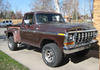
Truck: '78 F150 Ranger Lariat; 351m; calibration: (?) 72 11
Found vacuum diagram on forum. The green copied diagram that's difficult to see. It appears the yellow 3 ported switch on thermostat housing is set up: hot port going directly to vacuum amplifier; center port to distributor advance; cold port to 4 way tee, then to manifold vacuum.
QUESTION: Is this right? If so, understand why Vacuum amp/EGR would be hooked to hot port (EGR should open at higher temp) But if vacuum advance is on cold port, how would I get manifold vacuum on hot day at idle when cold port is closed?
Understand basic theory of 3 ported switch is to have hot port on manifold vacuum, center to advance and cold port to ported vacuum. What am I missing here?
Thanks for help.
Found vacuum diagram on forum. The green copied diagram that's difficult to see. It appears the yellow 3 ported switch on thermostat housing is set up: hot port going directly to vacuum amplifier; center port to distributor advance; cold port to 4 way tee, then to manifold vacuum.
QUESTION: Is this right? If so, understand why Vacuum amp/EGR would be hooked to hot port (EGR should open at higher temp) But if vacuum advance is on cold port, how would I get manifold vacuum on hot day at idle when cold port is closed?
Understand basic theory of 3 ported switch is to have hot port on manifold vacuum, center to advance and cold port to ported vacuum. What am I missing here?
Thanks for help.

MSEE
Joined: Apr 2004
Posts: 10,386
Likes: 35
From: Austin, TX

You are correct that a 3-port PVS transfers one common port to one of the two others based on temperature, but I don't recall which port is which. They are most commonly used on vacuum advances. For an EGR system, the only real essential piece you need is a 2-port PVS to keep vacuum from going to it before the engine warms up.
Can you send a link to the diagram in question?
Can you send a link to the diagram in question?
Thread Starter
|
New User
Joined: Nov 2012
Posts: 17
Likes: 0
From: Indiana
https://www.google.com/search?q=351m...qq_ZdNjFapyBM:
fmc400, here is link, I hope. If you can't see this, I'll try to add link to MilLion pic from his gallery.
fmc400, here is link, I hope. If you can't see this, I'll try to add link to MilLion pic from his gallery.
Thread Starter
|
New User
Joined: Nov 2012
Posts: 17
Likes: 0
From: Indiana
Senior User
Joined: Jan 2010
Posts: 147
Likes: 0
From: Phoenix, AZ
Look at the diagram again - hot port (passenger side of pvs) there is a T at the front of the carb and connects to the S port on the carb. Then continues to the vac amplifier. Center port to the distributor. Cold port (drivers side of pvs) to manifold vacuum - 4 way T if you are using the stock air cleaner.
If you have photoshop you can sharpen the image.
Mark
If you have photoshop you can sharpen the image.
Mark
Trending Topics
Thread Starter
|
New User
Joined: Nov 2012
Posts: 17
Likes: 0
From: Indiana
D24X4, thanks so much for the help. On diagram, there is a short vacuum line coming from carb spark port. At the end of that line there is an engineer note that says "cap". Are you saying that's a three way splitter with a cap on the end; the other ends intercepting the line coming from hot PVS port to vacuum amplifier?
Also, regarding the cold/passenger side port on PVS, I thought you always wanted vacuum advance on dist. coming from ported vacuum when cold and manifold vacuum when hot? With this set up, vacuum advance always comes from manifold vacuum.
Lastly, I noticed a reference in the diagram to a "blue" vacuum restrictor at the top of the 3 ported PVS we're talking about. What's up with that?
Also, regarding the cold/passenger side port on PVS, I thought you always wanted vacuum advance on dist. coming from ported vacuum when cold and manifold vacuum when hot? With this set up, vacuum advance always comes from manifold vacuum.
Lastly, I noticed a reference in the diagram to a "blue" vacuum restrictor at the top of the 3 ported PVS we're talking about. What's up with that?
FTE Stories
Ford Trucks for Ford Truck Enthusiasts

Top 6 Best Deals Available on New Fords & Lincolns Right Now
Brett Foote
This Hennessey Takes the Expedition Tremor's Off-Roading Capability to the Next Level
Verdad Gallardo
Top 10 Fords at 2026 Carlisle Ford Nationals
Joe Kucinski
3 Best / 3 Worst Parts of Modern Ford Ownership
Brett Foote
10 Amazing Upgrades That Solve Common Ford Truck Owner Headaches
Pouria Savadkouei
Every 2026 Ford Engine Explained
Brett Foote
10 Ugly Ford Trucks That We Still Kinda Love
Joe Kucinski
10 Things Every Truck Owner NEEDS (2026 Edition)
Michael S. Palmer
Rezvani's Latest Post-Apocalyptic Monster Is a Ford F-150 Raptor Underneath
Verdad Gallardo
Senior User
Joined: Jan 2010
Posts: 147
Likes: 0
From: Phoenix, AZ
For the T at the S port on the carb - I don't know why it says cap. Just use a regular 3 way T.
The pvs works off of temp and controls the vacuum source. I can't tell you exactly how it does this. Maybe FMC400 can explain it. Just run your lines the same as the diagram.
On my pvs - drivers side port is blue - restrictor is built in.
You should take the time to run all new vac lines too.
Mark
The pvs works off of temp and controls the vacuum source. I can't tell you exactly how it does this. Maybe FMC400 can explain it. Just run your lines the same as the diagram.
On my pvs - drivers side port is blue - restrictor is built in.
You should take the time to run all new vac lines too.
Mark

Thread
Thread Starter
Forum
Replies
Last Post
Ford59galaxie
1973 - 1979 F-100 & Larger F-Series Trucks
21
Feb 12, 2016 05:29 PM
Micheal78
1973 - 1979 F-100 & Larger F-Series Trucks
4
Feb 14, 2013 11:41 PM
bghnkinf250
1980 - 1986 Bullnose F100, F150 & Larger F-Series Trucks
11
May 30, 2009 05:30 AM
LARIAT 85
1980 - 1986 Bullnose F100, F150 & Larger F-Series Trucks
4
Aug 23, 2008 09:14 AM