1986 Ford F150 4WD - My First Truck
#61
 10-30-2012, 09:19 AM

Posting Legend
I realize your carb position will be quite different than mine, but here's what I did to the throttle bracket to accomodate the revised carb location on a Performer manifold:

To get there I cut the bracket in half and bolted the bottom on the manifold and the cable to the other half, and then put a piece of plate below them. I moved it around until I thought it was right and locked everything into place with c-clamps or vise grips. I then tested for slack in the throttle, wanting only a teeny bit, and kept testing until I got a straight shot with just a bit of slack as I'd already determined that slack translates to lost motion and crams the throttle action into whatever range is left. But you want a bit of slack to ensure the throttle returns to idle.
To get there I cut the bracket in half and bolted the bottom on the manifold and the cable to the other half, and then put a piece of plate below them. I moved it around until I thought it was right and locked everything into place with c-clamps or vise grips. I then tested for slack in the throttle, wanting only a teeny bit, and kept testing until I got a straight shot with just a bit of slack as I'd already determined that slack translates to lost motion and crams the throttle action into whatever range is left. But you want a bit of slack to ensure the throttle returns to idle.
#62
10-30-2012, 09:23 AM

Thanks again for the detail write-up on your progress and the pics along the way. The throttle cable is one item I'm still working on in my head as to how to route and keep my cruise control. I'm not entirely sure how that will work yet.
Regarding your carb, how did you plan on having it oriented? That will definitely play a factor in how your throttle linkage will work. (For some reason, your throttle linkage and stud location just doesn't look right, but that's coming from someone who hasn't mounted their Edelbrock yet.)
Regarding your carb, how did you plan on having it oriented? That will definitely play a factor in how your throttle linkage will work. (For some reason, your throttle linkage and stud location just doesn't look right, but that's coming from someone who hasn't mounted their Edelbrock yet.)
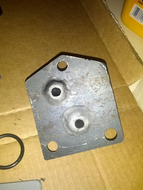
You can see in this picture what's going on with the carb ball-stud. The reason it's mounted down low is so the throttle cable can "pull" the carb throttle open. If the ball stud was in the upper hole (which, for all intents and purposes, looks like the right one), the throttle cable would have to "push" the carb throttle open.

#63
10-30-2012, 09:27 AM
I realize your carb position will be quite different than mine, but here's what I did to the throttle bracket to accomodate the revised carb location on a Performer manifold:
To get there I cut the bracket in half and bolted the bottom on the manifold and the cable to the other half, and then put a piece of plate below them. I moved it around until I thought it was right and locked everything into place with c-clamps or vise grips. I then tested for slack in the throttle, wanting only a teeny bit, and kept testing until I got a straight shot with just a bit of slack as I'd already determined that slack translates to lost motion and crams the throttle action into whatever range is left. But you want a bit of slack to ensure the throttle returns to idle.
To get there I cut the bracket in half and bolted the bottom on the manifold and the cable to the other half, and then put a piece of plate below them. I moved it around until I thought it was right and locked everything into place with c-clamps or vise grips. I then tested for slack in the throttle, wanting only a teeny bit, and kept testing until I got a straight shot with just a bit of slack as I'd already determined that slack translates to lost motion and crams the throttle action into whatever range is left. But you want a bit of slack to ensure the throttle returns to idle.
#64
10-30-2012, 09:36 AM

#65
10-30-2012, 09:37 AM
Posting Legend
I am going to have the carb oriented with the primaries on the engine-side of the intake manifold and the secondaries on the "passenger" side. The Offy dual plane manifold has smaller runners on the bottom and these runners are on top of the heater plate. Positioning the carb in this way will put the throttle linkage on the firewall side.
You can see in this picture what's going on with the carb ball-stud. The reason it's mounted down low is so the throttle cable can "pull" the carb throttle open. If the ball stud was in the upper hole (which, for all intents and purposes, looks like the right one), the throttle cable would have to "push" the carb throttle open.
You can see in this picture what's going on with the carb ball-stud. The reason it's mounted down low is so the throttle cable can "pull" the carb throttle open. If the ball stud was in the upper hole (which, for all intents and purposes, looks like the right one), the throttle cable would have to "push" the carb throttle open.
Awesome, thanks for the picture! I think I have an idea of how I'm going to do it... gonna try and test some of it out tonight. Does the throttle cable need to basically be a straight shot from the stop-nut on the bracket to the ball-stud on the carb? Specifcally, does the stop-nut need to be perpendicular to where the cable connects to the carb?
But, I'm not sure I understand "
#66
10-30-2012, 09:40 AM
Yes, given your application you do need the stud down low and the spring up high - exactly the opposite of what the V8's run.
I'm not sure what you mean by "stop-nut". But the throttle cable should be a straight shot, as much as is possible, to the ball stud and hit it at right angles to the throttle shaft in the carb. It doesn't have to be perfect but you don't want it pulling the throttle shaft to the side much or you'll be wearing where the butterflies hit the bore.
But, I'm not sure I understand "
 . But you've answered my question - keep the throttle cable as straight as possible. Thanks!
#67
10-30-2012, 12:36 PM

I took the double pulley off of my original alternator and put it on the new one. One of the pulleys was used to drive the AIR pump, but I am thinking of trying to use two belts from the crank pulley to drive the alternator. I've read a few times that a single v-belt is only good for about 90 amps, and my alternator is considerably bigger. The only issue I can see is that the double-pulley on the alternator seems to be a bit smaller for the original AIR pump drive. I need to do a little more research on this.
for alternator wiring, i don't remember what alt you're putting on there, and don't feel like digging way back to find out. in short, the 3 wires you found going back to the firewall are the alternator output wire and the 2 small wires send the alternator a signal to start up. i remember one of those should be always hot, and the other is a switched hot. if you're running a 3g alternator, it has a 3-pin connector on the side, with the pins labeled A, S, I. A = always hot. S = stator - pin an inch away, your harness should make that connection without you having to think about it. I = indicator light. i took the switched wire from the OEM alternator harness, ran it back up to the dash, mounted a light, and ran it back to this terminal of the alternator. works great.
and if you want to see how i did my idiot light, click on the van forum and do a search for threads i started, think i titled it "oil idiot light add-on" or something like that
#68
10-30-2012, 12:54 PM
for the pulley, you need the same diameter for both belts, or else it will be forced to slip constantly. IIRC the crank pulley works perfectly for that, and alternator pulleys are readily available from any junkyard that allows you to take your impact wrench inside. many old fords have the right one, and the ones on older volvos appear to be a perfect fit as well, but i haven't tested them yet.
for alternator wiring, i don't remember what alt you're putting on there, and don't feel like digging way back to find out. in short, the 3 wires you found going back to the firewall are the alternator output wire and the 2 small wires send the alternator a signal to start up. i remember one of those should be always hot, and the other is a switched hot. if you're running a 3g alternator, it has a 3-pin connector on the side, with the pins labeled A, S, I. A = always hot. S = stator - pin an inch away, your harness should make that connection without you having to think about it. I = indicator light. i took the switched wire from the OEM alternator harness, ran it back up to the dash, mounted a light, and ran it back to this terminal of the alternator. works great.
and if you want to see how i did my idiot light, click on the van forum and do a search for threads i started, think i titled it "oil idiot light add-on" or something like that
#69
10-30-2012, 08:34 PM
I got the pulley installed on the power steering pump and mounted it in its bracket. Question though... does the power steering pulley "bottom out" onto the pump itself? I installed mine like that, and there is clearance with the bracket bolts, and it turns freely, but I just want to make sure.
Actually... I just looked at the picture posted by AbandonedBronco here: https://www.ford-trucks.com/forums/1...-p-pulley.html
I think I installed my PS pump pulley backwards. It looks like it uses the forward groove on the crank pulley... and the way mine is lined up - it will use the center groove (three-groove crank pulley BTW). So it looks like I will get to pull it off tomorrow and put it back on the right way. I'm so excited... putting the pulley on with the installer is definitely a decent arm/hand workout because the dang pulley wants to spin and unscrew the jack bolt. Just kidding about the excited... it will probably take three beers (or more?) to get the initiative to redo it.
I should have taken pictures of the original yesterday before I disassembled it. I'm pretty sure that the rear bracket that the PS pump bracket bolts to goes on the "second set" of bosses from the front of the engine - i.e., they go in the bosses closest to the fuel pump.
Ran into an issue with the water pump. The one that the machine shop ordered for me has a much smaller "flange" where the pulley bolts to. As in the bolt pattern on my pulley is larger in diameter than the flange on the water pump. After a little research, it looks like I need this water pump: A1 Cardone Remanufactured Water Pumps 100-58338 - SummitRacing.com
Plus Summit says that water pump is for 1983-86 trucks. It looks like they ordered me a pump for a 1971-82 truck. Ahhhh... there's always something!
A few more bolt sizes for people who are interested:
(a) the three bolts that hold the PS pump to the bracket are M10x1.5x30mm
(b)the long bolt that the PS bracket pivot to the rear bracket is a 7/16xNC14 6 inches long
(c)the nuts to hold the PS tension bracket to the timing cover studs are M8x1.25
(d)the bolt to tighten down the PS bracket to the tension bar = 7/16xNC14 1 inch long
Gotta love the mixing and matching of standard and metric sizes... makes no sense to me. But then again, I wasn't even born when Ford built my truck. LOL
Last edited by mark1986F150; 10-30-2012 at 08:40 PM. Reason: clarification on PS bracket pivot
#70
10-30-2012, 09:05 PM
Okay, so I just went back out and checked and I did, in fact, install the PS pulley the right way. Doing some research on what's needed to run a double-pulley on the alternator... the way everything is right now, it looks like the PS pump will run off the center groove on the crank pulley and I need the rear and center groove to run the water pump / alternator with a double-pulley setup.
#71
10-31-2012, 02:38 AM
then it sounds like the only way to get what you want is to move the PS pulley forward to the forward-most groove. since i doubt your shaft is long enough for that, that means you get to play with mounting brackets to move the pump forward. from what i remember of the 6cyl mounting bracket, that'll be a pretty easy thing to do: space out the one little bracket from the timing cover, and put spacers in front of the vertical bracket piece that bolts onto those 2 holes in the block - not at those 2 holes but up where it mounts to the pump. add a couple longer bolts, and you're done.
#72
10-31-2012, 07:08 AM
then it sounds like the only way to get what you want is to move the PS pulley forward to the forward-most groove. since i doubt your shaft is long enough for that, that means you get to play with mounting brackets to move the pump forward. from what i remember of the 6cyl mounting bracket, that'll be a pretty easy thing to do: space out the one little bracket from the timing cover, and put spacers in front of the vertical bracket piece that bolts onto those 2 holes in the block - not at those 2 holes but up where it mounts to the pump. add a couple longer bolts, and you're done.
Edit: I just reread your post and it seems like I could pull the power steering pulley forward, but I will be limited by the length of the input shaft and might have to adjust the bracket also.
#73
10-31-2012, 08:17 AM

You can't pull the PS pump pulley too far forward, as it relies on a press-fit to hold it onto the shaft. Though, I imagine you could get a bolt with the right thread pattern that is short enough to hold the pulley on, there would still be the risk of it spinning.
On my 300, the PS pump uses the forward most crankshaft groove. The alternator and water pump run off of the back two grooves. Though, mine is an 80 to 83 model, and your valve cover shows an 84 to 86 model. I doubt it makes much of a difference though.
I see you're on the right track with the carburetor and the intake. Have you fabbed up your heating plate yet? Also, consider wrapping your headers with header wrap so they don't radiate as much heat if you're worried about your starter.
How are you going to run your exhaust? I see a lot of people step down from the 2.5'' collector size and run them 2'' or 2 1/4'' true duals out the back. My plan is a set of Purple Horny header mufflers and having a shop do me up true 2 1/2'' mandrel bent duals. I understand wanting the exhaust to scavenge (and I say the following at the risk of sounding like a moron), but I don't like the idea of starting out at a big size and stepping down to a smaller size. The idea of a free-flowing exhaust is to reduce back pressure as much as possible, and creating a bottle-neck doesn't help the idea of free flowing.
There's not much you can do to reduce the low-end torque nature of these motors. About the only thing that would hurt the low end torque is putting in a cam with too much duration.
#74
10-31-2012, 08:28 AM
You can't pull the PS pump pulley too far forward, as it relies on a press-fit to hold it onto the shaft. Though, I imagine you could get a bolt with the right thread pattern that is short enough to hold the pulley on, there would still be the risk of it spinning.
On my 300, the PS pump uses the forward most crankshaft groove. The alternator and water pump run off of the back two grooves. Though, mine is an 80 to 83 model, and your valve cover shows an 84 to 86 model. I doubt it makes much of a difference though.
I see you're on the right track with the carburetor and the intake. Have you fabbed up your heating plate yet? Also, consider wrapping your headers with header wrap so they don't radiate as much heat if you're worried about your starter.
How are you going to run your exhaust? I see a lot of people step down from the 2.5'' collector size and run them 2'' or 2 1/4'' true duals out the back. My plan is a set of Purple Horny header mufflers and having a shop do me up true 2 1/2'' mandrel bent duals. I understand wanting the exhaust to scavenge (and I say the following at the risk of sounding like a moron), but I don't like the idea of starting out at a big size and stepping down to a smaller size. The idea of a free-flowing exhaust is to reduce back pressure as much as possible, and creating a bottle-neck doesn't help the idea of free flowing.
There's not much you can do to reduce the low-end torque nature of these motors. About the only thing that would hurt the low end torque is putting in a cam with too much duration.
On my 300, the PS pump uses the forward most crankshaft groove. The alternator and water pump run off of the back two grooves. Though, mine is an 80 to 83 model, and your valve cover shows an 84 to 86 model. I doubt it makes much of a difference though.
I see you're on the right track with the carburetor and the intake. Have you fabbed up your heating plate yet? Also, consider wrapping your headers with header wrap so they don't radiate as much heat if you're worried about your starter.
How are you going to run your exhaust? I see a lot of people step down from the 2.5'' collector size and run them 2'' or 2 1/4'' true duals out the back. My plan is a set of Purple Horny header mufflers and having a shop do me up true 2 1/2'' mandrel bent duals. I understand wanting the exhaust to scavenge (and I say the following at the risk of sounding like a moron), but I don't like the idea of starting out at a big size and stepping down to a smaller size. The idea of a free-flowing exhaust is to reduce back pressure as much as possible, and creating a bottle-neck doesn't help the idea of free flowing.
There's not much you can do to reduce the low-end torque nature of these motors. About the only thing that would hurt the low end torque is putting in a cam with too much duration.
I did fab up a heater plate for the intake. I used 1/4" steel with two 3/8 NPT street elbows. I used some "steel" epoxy around the fittings where they penetrate the plate to (hopefully) eliminate any possibility of leaking around the fittings. I used rubber/cellulose gasket material to make a gasket for the plate.

That's good advice with the header wrap. I will use it around the starter because there is only about 1" of clearance between the header and the starter and it will probably cook the starter pretty fast.
As far as the exhaust... I've gotten under the truck to start getting an idea of how I'm gonna do it. To be honest, it's probably going to be a pain, because going straight back from the front collector will hit the rear collector. So I'm going to have to install a slight bend immediately after the front collector to avoid hitting the back collector. There is also not a lot of room between the header and the bellhousing (4-speed standard). I think I will end up putting one pipe (from the rear collector) over the tranny crossmember and the pipe from the front collector under the crossmember. After the bellhousing there is quite a bit of room, so the plan is to use a narrow X-pipe (from Summit) and terminate in a Flowmaster 40 series delta with dual in/dual out and finally with a pair of turndowns.
#75
10-31-2012, 08:54 AM
Posting Legend
If you do things like go over and under the transmission's crossmember you might consider installing flanged-connections in places that would allow you to get the exhaust off without cutting it. I did that when installing the exhaust on Dad's truck during the ZF5 swap and was extremely glad I did because the throwout bearing came apart within a couple of weeks and I had to take the tranny back out. If I'd had to cut the exhaust I would have cried, but since I had the connection right there it was easy.