1986 Ford F150 4WD - My First Truck
#31
 10-01-2012, 07:48 AM

Posting Legend
I am not too hot on electric fans. If you are going to get some that will do something, you should go get some OEM Ford fans out of the junkyard, and if you do that, you should upgrade the alternator also to a 3G. You will need some relays, the controller you mentioned, and they will need to be wired in to the A/C system if you are going to use air.
The factory fan is a much simpler system.
The factory fan is a much simpler system.
#32
10-03-2012, 11:35 AM

if i were to add an e-fan, i'd put it in front of the rad as a pusher and leave the stock fan in place, as most engine-driven fans move a lot more air than an affordable electric model.
i added a 12" pusher i got for free onto my diesel, and i can't even notice a temp difference if its running or not, even when i'm working on fairly high temps (230). note that that is with a poor fan clutch, so i hoped the e-fan would help some
i added a 12" pusher i got for free onto my diesel, and i can't even notice a temp difference if its running or not, even when i'm working on fairly high temps (230). note that that is with a poor fan clutch, so i hoped the e-fan would help some
I am not too hot on electric fans. If you are going to get some that will do something, you should go get some OEM Ford fans out of the junkyard, and if you do that, you should upgrade the alternator also to a 3G. You will need some relays, the controller you mentioned, and they will need to be wired in to the A/C system if you are going to use air.
The factory fan is a much simpler system.
The factory fan is a much simpler system.
Most of my order from Summit came in yesterday, and I just dropped off head components and the cam at the machine shop. He should have my pistons in by the end of the week and will hopefully start machining next week.
In the mean time, I am keeping busy with cleaning up the engine bay and painting components. I think I'm going to paint the block and all brackets flat black, and the head, valve cover, timing cover, cam cover, and oil pan in "new Ford grey". I also need to finish painting the interior pieces... only a couple left to go. Then I can hit them with some fine sand paper, do one more coat, and hopefully start putting the interior back together. I am a bit hesitant to put the dash back in though. The vacuum actuator for the AC-mode selector flap keeps binding the flap. I need to figure out why it's doing that before I put the dash back in. But in order to do that I need to get a small vacuum pump so I can test it out, and that will require a trip to Harbor Freight. I'm thinking about just fixing the selector flap in the "open" position so air only blows through the defrost/floor vents. The only reason that it's in there is to defrost the windows when it's cold... it's not like I'm using it for comfort considering that the AC system is disconnected. But it would be nice for it to be functional.
I also want to figure out why this blasted thing is still leaking from the firewall seam. I've POR15 and fiberglassed it on the outside, and used some of that Great Foam stuff on the inside and it STILL leaks. I am thinking about pulling the foam out (probably wasn't a good choice to begin with) and "caulking" some asphalt roofing adhesive into the seam to seal it up. Or maybe just learn to live with a little water on the floor when it rains.
#33
10-03-2012, 01:38 PM
Posting Legend
I hope you are upgrading the wiring from the alternator to the solenoid with a bigger alternator. The existing wiring wasn't all that strong for a 60 amp alternator, and I don't think it would handle 140 amps very long. Further, I hope you are bypassing the shunt for the ammeter as it was also designed for 60 amps and will probably get quite hot at more than twice that.
On the A/C mode door, is the hinge broken? Many of them are and bind when you try to move them.
And, with all the work you are doing to the truck I wouldn't settle for any water on the floor. That is a recipe for rusted floor pans and ruined carpet. Pull the foam and try seam sealer.
On the A/C mode door, is the hinge broken? Many of them are and bind when you try to move them.
And, with all the work you are doing to the truck I wouldn't settle for any water on the floor. That is a recipe for rusted floor pans and ruined carpet. Pull the foam and try seam sealer.
#34
10-03-2012, 01:46 PM
I hope you are upgrading the wiring from the alternator to the solenoid with a bigger alternator. The existing wiring wasn't all that strong for a 60 amp alternator, and I don't think it would handle 140 amps very long. Further, I hope you are bypassing the shunt for the ammeter as it was also designed for 60 amps and will probably get quite hot at more than twice that.
On the A/C mode door, is the hinge broken? Many of them are and bind when you try to move them.
And, with all the work you are doing to the truck I wouldn't settle for any water on the floor. That is a recipe for rusted floor pans and ruined carpet. Pull the foam and try seam sealer.
On the A/C mode door, is the hinge broken? Many of them are and bind when you try to move them.
And, with all the work you are doing to the truck I wouldn't settle for any water on the floor. That is a recipe for rusted floor pans and ruined carpet. Pull the foam and try seam sealer.
It has a single-wire hookup and includes a 10AWG replacement charging wire. So the existing alternator harness will be gone.
As far as the AC door goes... I looked at it and noticed that the little push-pin that holds it to the actuator arm was pretty floppy. So I took it out and replaced it with a small nut/bolt. It still binds up though. It seems like it doesn't rotate fast enough to catch the moving air from the blower side to swing it around and block the front vent inlet. I'm not sure if that's the case, but that sort of seemed to be what was happening. I have the nut/bolt loose enough that I can rotate it freely, but tight enough (just barely tight, really) to keep the door from floppy all over the place.
I have Herculined the floor inside the cab, so I don't think I'll get any rusting. But yes, wet carpet is pretty gross. When I got the truck, the guy had been driving it around for awhile with the leaks and that carpet was naaaasty. I wore a dust mask when I pulled it out because it was so moldy. And that's when I decided I would Herculine it and not bother with new carpet.
Is seam-sealer pretty thick when you apply it? Can I use a paintbrush and "dab" it into place? Or does it come out of a tube like caulk?
Last edited by mark1986F150; 10-03-2012 at 01:48 PM. Reason: ac door
#35
10-03-2012, 06:32 PM

#36
10-03-2012, 06:41 PM

#37
10-03-2012, 08:34 PM
Posting Legend
While it is true that #10 is good for 30 amps continuous in all the tables, auto manufacturers use smaller wire than the tables show in most cases. That doesn't mean I'm suggesting going with small wire, but just that you will find smaller wire in our trucks as well as almost all auto applications than the tables show. And, fuses can't hurt.
But, don't forget that there is a shunt (resistor) in the wiring, and that is what makes the ammeter work. If you take it out your ammeter will not work. If you don't take it out and utilize much of the 140 amp capacity of the new alternator you will probably melt it down as it is designed to handle the output of the old alternator - 60 amps. Somewhere on FTE there as a discussion of what resistance would be needed to make the ammeter peg for larger alternators, so maybe you can find that if you want yours to work.
But, don't forget that there is a shunt (resistor) in the wiring, and that is what makes the ammeter work. If you take it out your ammeter will not work. If you don't take it out and utilize much of the 140 amp capacity of the new alternator you will probably melt it down as it is designed to handle the output of the old alternator - 60 amps. Somewhere on FTE there as a discussion of what resistance would be needed to make the ammeter peg for larger alternators, so maybe you can find that if you want yours to work.
#38
10-04-2012, 12:21 AM
personally, i went with the 3g, using a 1ga wire because its what i had laying around, and did not use a fuse. the original application from which i took my alternator used a 175a fuse and a 6ga wire coming from the alternator.
as gary mentioned above, the auto industry has a reputation for running wires smaller than seem to be proper, and fires are quite rare. as i said above, exceeding the rating WILL cause the wire to heat up, though not always to a catastrophic level. lets take your original alternator with original loads for an example. you start the engine and immediately turn on the headlights, wipers, and heater fan, and quickly bring the engine to a cruising speed at which the alternator is producing its full output. lets say that the loads total 35 amps, but the alternator is also recharging the battery from starting the engine, so for the first 30 seconds its putting out its full 60 amps, then is down to 35 amps to maintain these loads. in that first 30 seconds, the charging wire heated up from 30*f to 80*f, and with the combination of additional heat from being slightly above its rating combined with the wind passing over it as you drive, the wire maintains a temp of 80-100*, and all is well, you don't have a problem.
note that all numbers i mentioned above are a speculation i assembled to make a point, and are NOT expected to be accurate, though they perfectly demonstrate the conditions the stock charging wire sees. obviously, when you double both the charging capacity and the load on the system, that little 10ga wire is no longer enough, and will probably melt down in short order if used that heavily.
automakers tend to go with small wires to save costs, owners who rewire things tend to go with oversize wires to avoid any slight risk of a problem, without regard to the greater up-front cost.
at the end of the day, bigger costs more up front, but reduces risk down the road.
if you do choose to fuse your system, make sure the fuse is at least 20% greater than the maximum capacity of the alternator. a ford taurus uses a 175a fuse on a 130a alternator. the fuse cannot blow unless the wire has a hard short to a ground, and thats a good thing for this application
#39
10-04-2012, 08:10 AM

30 amps on a 10 gauge wire is house wiring rules from the NEC code book. I tend to use that, and I see other people do also, but it's a conservative figure when it comes to some automotive applications. In reality, you need to figure voltage drop(the wire from the alternator to the battery is usually fairly short) and the temp rating of the wire and the ambient temperature the wire is exposed to. True it gets hot under the hood, but when current is flowing through the wire, there is a lot of air whizzing around it from the fan. House wiring is imbedded in a flammable wood wall with no airflow around it.
All that being said, I do stay in the neighborhood of the house wiring specs, + or - a little bit. And you can do what Ford did sometimes, if all you have laying around is 12 or 10 gauge wire, you can run two or three side by side to increase the capacity if you do not have the large wire or the lugs to go with it.
All that being said, I do stay in the neighborhood of the house wiring specs, + or - a little bit. And you can do what Ford did sometimes, if all you have laying around is 12 or 10 gauge wire, you can run two or three side by side to increase the capacity if you do not have the large wire or the lugs to go with it.
#40
10-04-2012, 11:37 AM
#41
10-05-2012, 11:34 AM
Picked up the new dual-core radiator and intake manifold heat-riser gasket today. I'm going to try my hand at a little fabrication this weekend. The plan is to see if the radiator will fit in the stock brackets - if it doesn't I'll weld up some new ones. I'm also planning to make the water-plate for the intake manifold so I can run some heat to it. I'll post pictures of the process.
OH YEAH, AND IT'S FRIDAY!!!!
OH YEAH, AND IT'S FRIDAY!!!!
#42
10-19-2012, 08:48 AM
Wow it's been two weeks since I've updated. Been really busy with work/putting the motor together. The motor is getting pretty close - the head is on, water pump, distributor, all internals are done, lifters, rockers, valve cover, etc. I haven't really run into any major issues. I did a couple of stupid things... I hammered on the harmonic balancer before reading that you should use the tool. That necessitated me taking the balancer back off and checking the thrust bearing... everything looked okay so I reassembled it. I distorted the front crank seal by using a socket that was too small to hammer it in so I got a new seal and rented a seal installation kit from Autozone. Besides those mistakes though, nothing has really gotten in the way.
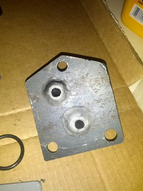
I fabbed up my heater plate for the intake. I used 1/4" steel plate and two 3/8" street elbows. I drilled and tapped a couple of holes to screw in the elbows. Originally I used the gasket from my rebuild kit for a template, but the gasket wasn't really a good fit compared to the actual water jacket on the intake. So I used some calipers to take actual measurements and came up with a plate that fits much better. I wish I had paid more attention when I was tapping the holes for the elbows because I ended up with some weird positioning of the elbows due to the starting point for the threads. I think it probably would have been hard to tap the holes to end up at a certain rotation on the elbows after installing though. I will ultimately use a couple more fittings to get the nipples from the elbows to line up in a position that works better for plumbing them in. I used teflon tape to seal the threads, and I got some plumbing epoxy and formed it to the end of the elbows on the backside of the plate to seal them up. I also bought a cellulose/rubber gasket sheet to cut out a new gasket between the plate and the manifold, and used some RTV on both sides of the gasket to ensure a good seal. I painted the plate with flat black 500-degree paint... hopefully the paint will hold up given the close proximity to the header.
On a side note, I would not recommend using anything thinner than probably 3/16" plate to make the heater plate. I had originally tried 16-GA steel, but it was too thin and bent all over the place. I used 1/4" plate because that's what I found at Lowes. The build that I modeled mine after used 3/16" steel, which seemed to work out well. But I would recommend going with as thick of a steel plate as you can find because (1) it won't bend/warp when you drill and tap or weld in your elbows and (2) it will hold a little more heat in (more steel = more heat capacity).

I am getting really close to getting the motor finished. Today when I get home I am going to fabricate some "oval" bolts with a step in them so I can bolt down the header and intake manifold. The bottom flange on the header is about 0.05" thinner than the flanges on the intake manifold and the washers I got sit at an angle on the studs when I bolt them down. So making the stepped washers will allow me to get proper force on the manifolds to bolt them down and (hopefully!) not have any leaks. To be honest, I am kind of disappointed with the quality of the Hedman header... the tube flanges aren't flush with the main header flange and the paint is rough/chipped in a few places. But I think once I have made the step washers it will work out okay.
I also managed to lose a few bolts and had to go buy replacements. For anybody who is interested, here are some of the bolt patterns that the motor uses:
I will hopefully finish getting the moto mocked up today/tomorrow and then put it back in the truck Sunday. After that I will have to do a little plumbing for the fuel line, a little wiring for my cab harness due to my single-wire alternator, and weld up exhaust tubing from the header outlets back to my x-pipe. The goal is to fire it up next weekend!
I fabbed up my heater plate for the intake. I used 1/4" steel plate and two 3/8" street elbows. I drilled and tapped a couple of holes to screw in the elbows. Originally I used the gasket from my rebuild kit for a template, but the gasket wasn't really a good fit compared to the actual water jacket on the intake. So I used some calipers to take actual measurements and came up with a plate that fits much better. I wish I had paid more attention when I was tapping the holes for the elbows because I ended up with some weird positioning of the elbows due to the starting point for the threads. I think it probably would have been hard to tap the holes to end up at a certain rotation on the elbows after installing though. I will ultimately use a couple more fittings to get the nipples from the elbows to line up in a position that works better for plumbing them in. I used teflon tape to seal the threads, and I got some plumbing epoxy and formed it to the end of the elbows on the backside of the plate to seal them up. I also bought a cellulose/rubber gasket sheet to cut out a new gasket between the plate and the manifold, and used some RTV on both sides of the gasket to ensure a good seal. I painted the plate with flat black 500-degree paint... hopefully the paint will hold up given the close proximity to the header.
On a side note, I would not recommend using anything thinner than probably 3/16" plate to make the heater plate. I had originally tried 16-GA steel, but it was too thin and bent all over the place. I used 1/4" plate because that's what I found at Lowes. The build that I modeled mine after used 3/16" steel, which seemed to work out well. But I would recommend going with as thick of a steel plate as you can find because (1) it won't bend/warp when you drill and tap or weld in your elbows and (2) it will hold a little more heat in (more steel = more heat capacity).
I am getting really close to getting the motor finished. Today when I get home I am going to fabricate some "oval" bolts with a step in them so I can bolt down the header and intake manifold. The bottom flange on the header is about 0.05" thinner than the flanges on the intake manifold and the washers I got sit at an angle on the studs when I bolt them down. So making the stepped washers will allow me to get proper force on the manifolds to bolt them down and (hopefully!) not have any leaks. To be honest, I am kind of disappointed with the quality of the Hedman header... the tube flanges aren't flush with the main header flange and the paint is rough/chipped in a few places. But I think once I have made the step washers it will work out okay.
I also managed to lose a few bolts and had to go buy replacements. For anybody who is interested, here are some of the bolt patterns that the motor uses:
- Header/Intake manifold: 3/8"xNC16x1.25" (I used 2" studs though)
- Intake manifold dowel pin (located at front of head above #2 cylinder): 5/16" (I used a 5/16" roll-pin)
- Distributor hold-down: 5/16"xNC18x0.75"
- Fuel pump: 5/16"xNC18x1.25" (I am using a lock washer which is why I went with 1.25", without lock washers a 1.25" bolt is about 0.05" too long) EDIT: Use 1" bolts. The 1.25" worked on the front-bolt of the pump but was too long for the rear bolt. So I swapped both for 1" bolts.
- Flywheel: 7/16"xNC20x1"
- Water elbow: 5/16"xNC18x1"
- Plug by fuel pump: 3/8"xNC16x0.5" plug
- Second plug by fuel pump: 7/16"xNC14x0.5" plug
- Blind hole on intake to bolt down heater plate: 3/8"xNC16x0.75" (might need a smaller bolt if you use thinner plate, I used 1/4" plate)
I will hopefully finish getting the moto mocked up today/tomorrow and then put it back in the truck Sunday. After that I will have to do a little plumbing for the fuel line, a little wiring for my cab harness due to my single-wire alternator, and weld up exhaust tubing from the header outlets back to my x-pipe. The goal is to fire it up next weekend!
Last edited by mark1986F150; 10-19-2012 at 09:06 AM. Reason: grammar mistake, added more bolt sizes
#43
10-19-2012, 11:41 AM

Looking good! If you haven't figured out all of your alternator and electric fan woes, make sure to check out the sticky threads as there are a ton of great write-ups on both of these projects. And, if you are going to do your alternator, you might as well update the wiring harness on your headlights too.
Just food for thought....
Just food for thought....
#44
10-19-2012, 12:38 PM
i'm not quite sure why you got stuck with funny angles on the elbows. as you probably know, pipe thread should be cut on a taper, so its loose when you start it and gets tighter as you go in. as a result, you get to keep tightening until you reach the angle you want - unless you ran the tap too far in and the holes are too big now.
#45
10-19-2012, 01:41 PM
i'm not quite sure why you got stuck with funny angles on the elbows. as you probably know, pipe thread should be cut on a taper, so its loose when you start it and gets tighter as you go in. as a result, you get to keep tightening until you reach the angle you want - unless you ran the tap too far in and the holes are too big now.